Sime MURELLE EQUIPE 100 BOX ErP User, Installation And Servicing Instructions
Hide thumbs
Also See for MURELLE EQUIPE 100 BOX ErP:
- Original instructions manual (73 pages) ,
- Manual (72 pages) ,
- User, installation and servicing instructions (56 pages)
Advertisement
Quick Links
Advertisement

Related Manuals for Sime MURELLE EQUIPE 100 BOX ErP


Summary of Contents for Sime MURELLE EQUIPE 100 BOX ErP
- Page 1 Cod. 6322834 - 04/2015 murEllE EQuipE 100 - 150 BoX Erp USER, INSTALLATION AND SERVICING INSTRUCTIONS EnsurE that thEsE instructions arE lEft for thE usEr aftEr complEtion of thE BEnchmarK sEction plEasE rEad thE important noticE within this guidE rEgarding your BoilEr warranty 199838...
- Page 2 SAFE HANDLING This boiler may require 2 or more operatives to move it into its installation site, remove it from its packaging and during movement into its installation location. Manoeuvring the boiler may include the use of a sack truck and involve lifting pushing and pulling.
-
Page 3: Table Of Contents
IPX4D CONTENTS DEVICE DESCRIPTION................pag. INSTALLATION. -
Page 4: Device Description
NOTE: The installation must incorporate a hydraulic separator or plate heat exchanger. The hydraulic separator available from Sime Ltd is supplied with modules in a kit code 8101550 and the tubes connecting the hydraulic separator in the kit code 8101534. It can be assembled on the left-hand side by moving the system supply/return manifold blind flanges. - Page 5 NOTE: The installation must incorporate a hydraulic separator or plate heat exchanger. The hydraulic separator available from Sime Ltd is supplied with modules in a kit code 8101550 and the tubes connecting the hydraulic separator in the kit code 8101534. It can be assembled on the left-hand side by moving the system supply/return manifold blind flanges.
- Page 6 TECHNICAL SPECIFICATIONS MURELLE EQUIPE 100 BOX ErP 150 BOX ErP Generators with a heat output kW 46.7 n° Heat output Nominal (80-60°C) (Pn max) 93.4 140. 1 Nominal (50-30°C) (Pn max) 102.0 153.0 Minimum (80-60°C) (Pn min) Minimum (50-30°C) (Pn min) 10.5 10.5 Heat input (*)
- Page 7 OPERATING DIAGRAM (fig. 2) 14 Heating return probe (SR) 15 Pressure transducer 1 Cascade delivery supply probe (SMC) 16 Single module drain 2 Hydraulic compensator 17 Non return valve 3 Antifreeze siphon sensor (SB/SA) 18 Pump high efficiency 4 Safety valve 3.5 bar 19 3-way isolation/drain valve 5 Condensation drain siphon 20 Isolation valve...
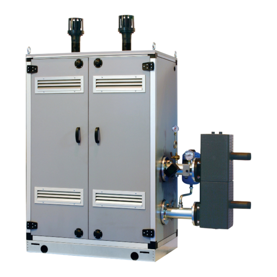
- Page 8 MAIN COMPONENTS (fig. 3) Code 8111227 Model MURELLE EQUIPE 100 BOX ErP Serial n. 9999999999 PAR 1 = 6 (G20) / 14 (G31) PAR 2 = 9 1 System return manifold 2 Gas isolation valve 3 System supply manifold 4 Gas valve 5 Fan 6 Safety thermostat 95°C...
-
Page 9: Installation
INSTALLATION The unit is suitable for external installation – Hydraulic separator kit code 8101550. VENTILATION in a fixed location. – Polypropylene exhaust manifold kit for The following is provide for your guidance It must be installed by qualified engineers indoor installation (purposely treated to only, and assumes the ventilation air is in compliance with all instructions con- resist weathering when installed out-... - Page 10 The system should be treated in accord- drain connection 4cm²/KW of net heat input ance with BS 7593. Sime Ltd recommend only the use of Fernox products for the The condensate drain must be connected A single generator (48KW net input) would...
- Page 11 The indicated solutions have the exhaust to resist weathering when installed out- sory assembly see fig. 5. manifold positioned both on the modules. doors. ø D MODEL Murelle Equipe 100 BOX ErP 160 2020 Murelle Equipe 150 BOX ErP 160 2055 Fig. 6...
- Page 12 TUBES CONNECTING THE HYDRAULIC SEPARATOR KIT (fig. 7) The connecting pipes for the hydraulic sep- arator are supplied in kit 8101534. The kit is made up of the following compo- nents (fig. 7): – System supply flanged section code 6291965 –...
- Page 13 CONNETTORE CABLATO (cod. 6319173) WIRED CONNECTOR (cod 6319173) DIP SWITCH DIP SWITCH GESTIONE IN CASCATA GESTIONE IN MODBUS 1 2 3 MODBUS MANAGEMENT CASCADE MANAGEMENT COMUNICAZIONE MODBUS MODBUS COMMUNICATION TAB. PAR 17 INST INSTALLER PARAMETER SETTING: PAR 17 INST No. Data Bit Eventy Stop Bit Baud Rate...
- Page 14 MODBUS BOILER VARIABLES LIST Function Variable description Digital variables Boiler CH Enable/Request Request CH zone 1 Boiler DHW Enable Enable DHW preparation Boiler Water Filling Function Not used State CH zone 1 Boiler CH Mode Boiler DHW Mode State preparation DHW Boiler Flame Status State presence flame State presence alarm...
- Page 15 HYDRAULIC SEPARATOR The hydraulic separator (available from is supplied separately in a kit Sime Ltd) code 8101550 complete with gaskets, nuts and fastening screws (figure 9). It is mandatory to include a hydraulic separa- tor in the assembly of the 100-150 BOX ErP.
- Page 16 CONNECTIONS 230V – 50 Hz single phase voltage is required using a fuse protected main switch NOTE: Sime declines all responsibility for Each module is supplied with a power cord with at least 3 mm. between contacts. injury or damage to persons, animals or which, if replacement is required, it must Observe the L –...
- Page 17 2.11.2 Electrical connection of generators in sequence/cascade (fig. 11/a) Line Neutral Safety thermostat 100°C Pmin Water pressure switch min. 0.9 bar Pmax Water pressure switch max. 3 bar External sensor Cascade supply probe RS-485 Cascade management board The RS-485 board for management in sequence/cascade is placed at the rear of the control panel of each individual gen- erator as shown in the figure.
- Page 18 2.11.4 Remote control SIME HOME con- nection (optional) The heating demand can be controlled by use of remote control unit SIME HOME (code 8092280/81) The remote control unit allows for complete control, except lockout reset. The generator will display CR.
-
Page 19: Characteristics
OFF = Electricity supply to boiler is on but nor ready for PC CONNECTION functioning. However, the protection functions To be used only with the SIME programming kit and only are active. by authorised personnel. Do not connect other elec- tronic devices (cameras, telephones, mp3 players, etc.) - Page 20 ACCESS TO INSTALLER’S INFORMATION For access to information for the installer, press the key (3 fig. 12). Every time the key is pressed, the display moves to the next item of information. If the key is not pressed, the system automatically quits the function. If there is no expansion board (MIXED ZONE or INSOL) the relative info will not be displayed.
- Page 21 18. Display of Heating return sensor value (SR) Display of valve closing opening control with board MIXED 18. Visualizzazione valore sonda ritorno riscaldamento (SR) 29. Visualizzazione comando chiusura valvola con schedino ZONE 2 (respectively ON and OFF) ZONA MIX 2 (rispettivamente ON e OFF) 30.
- Page 22 The standard visualisation returns auto- of voltage 1 = Enabled matically after 60 seconds, or by pressing Allocation of SIME HOME channels 0 = Not assigned in h x 100 (es. 14.000 e 10) one of the control keys (2 fig. 12).
- Page 23 BOILER PAR 2 PARAMETERS INSTALLER Instantaneous with diverter valve and flowmeter EXPANSION CARD Instantaneous with diverter valve PAR DESCRIPTION RANGE UNIT OF INC/DEC DEFAULT flowmeter and solar combination MEASUREMENT UNIT SETTING Number of expansion boards 0 ... 3 Remote control DHW cylinder with diverter valve and cylinder sensor Mix valve stroke time 0 ...
- Page 24 TABLE 4 (SM - SR - SF sensors) valve. Ignition failure with consequent acti- – Interface with the following electronic systems: remote control SIME HOME vation of block can be due to: Temperature (°C) Resistance (Ω) code 8092280/81, thermal regulator 12.090...
- Page 25 1000 1200 1400 1600 1800 2000 HEAD AVAILABLE The speed of the modulating pump system TO SYSTEM (fig. 14) is set as default (installation parameter PAR 13 = Au). Residual head for the heating system is shown as a function of rate of flow in the graph in fig.
-
Page 26: Commissionimg, Use And Maintenance
If required mum and maximum output. Com- contact Sime Ltd for further assist- Competence to carry out the pare the results to the following: ance. - Page 27 GAS CONVERSION (fig. 17) 1) Press and hold the button down for a few seconds This operation must be performed by authorised personnel using original Sime 2) Press the button for a few seconds components. The standard display will automatically return after 10 seconds.
- Page 28 MAINTENANCE (fig. 20) To ensure correct operation and efficiency it is important that the boiler is serviced at regular intervals, at least once a year (this may also be a condition of the warranty). Servicing must only be done by a qualified technician.
- Page 29 4.5.3 Pump high efficiency diagnose and remedy (fig. 22/a) LED diagnose and remedy Led color Meaning Diagnostic Cause Remedy Continuous green Normal running Pump run as expec- Normal operation ted or is faced to a phenomenon that shortly affects its running Abnormal situation Pump will restart...
- Page 30 FUNCTIONING ERRORS APRE When there is a functioning error, an alarm Circuito Circuito appears on the display and the blue lumi- riscaldamento 2 riscaldamento 2 nous bar becomes red. Descriptions of the errors with relative alarms and solutions are given below: Circuito riscaldamento 2 –...
- Page 31 APRE – SAFETY/LIMIT THERMOSTAT ERROR ALARM 07 (fig. 23/6) If either the 95 degree stat or the heat Circuito exchanger safety stat opens, the burner riscaldamento 2 will turn off and ALL 07 will be displayed. Press the key of the controls (2) to start up the boiler again.
- Page 32 (impianto tre zone) APRE Circuito – “ALL 15” FAN ERROR (fig. 23/12) – SAFETY THERMOSTAT INTERVENTION – AUXILIARY SENSOR ANOMALY (S3) riscaldamento 2 Circuito The fan speed does not fall within the SECOND MIXED ZONE “ALL 22” (fig. “ALL 26” (fig. 23/20) riscaldamento 2 rated speed range.
- Page 33 CAUTION: In the event of sequence/cas- The boiler restarts when the boiler three- cade connection, error codes 70 and 71 zone system configuration is activated will appear on the SIME HOME remote – RS-485 BOARD COMMUNICATION control display: - ALARM 70...
- Page 34 SERVICE RECORD It is recommended that your heating system is serviced regularly and that the appropriate Service Interval Record is completed. Service Provider Before completing the appropriate Service Record below, please ensure you have carried out the service as described in the manufacturer’s instructions. SERVICE 01 SERVICE 02 Date:...
-
Page 37: Fault Finding
FAULT FINDING If an electrical fault occurs on the appliance then there is a short circuit. All switches including thermostat on test the preliminary electrical system checks Meter set on ø (ohm) x 100 scale. Repeat leads from L to E - if meter reads other must be carried out first. - Page 38 APPENDIX 1 INDUSTRY GUIDANCE FOR INSTALLERS ON CONDENSATE DRAINAGE PIPE INSTALLATION This guidance is endorsed by HHIC members. 1. BACKGROUND During recent winters the UK has experienced prolonged spells of extremely cold weather - down to minus 20 C and below in many areas. This resulted in a significant increase in the number of calls to boiler manufacturers and heating engineers from householders with condensing (high efficiency) boilers where the condensate drainage pipe had frozen and become blocked with ice, causing the boiler to shut down.
- Page 39 2.1 INTERNAL TERMINATION: Wherever possible, the condensate drainage pipe should be terminated at a suitable internal foul water discharge point such as (a) an internal soil and vent stack or (b) an internal kitchen or bathroom waste pipe, washing machine waste pipe etc. A suitable permanent connection to the foul waste pipe should be used.
- Page 40 The use of fittings, elbows etc should be kept to a minimum and any internal “burrs” on cut pipework should be removed so that the internal pipe section is as smooth as possible. The customer/householder should be advised that even with the above measures this type of installation could freeze, and that if this were to occur then boiler shutdown could result, requiring remedial action - possibly involving a chargeable engineer call-out.
- Page 41 NOTES The Benchmark Commissioning Checklist should be completed as required to record details of the condensate drainage pipe installation. Where an external condensate drainage pipe is installed, the customer should be made aware of the risks and consequences of its freezing and offered the option to fit trace heating (or other measures approved by the boiler manufacturer or service organisation).
- Page 42 Figure 1 – Connection of condensate drainage pipe to internal soil and vent stack Boiler Visible air break 75 mm trap Visible air break and trap not required if there is a trap with a minimum condensate seal of 75 mm incorporated into the boiler Soil and vent stack Invert 450 mm minimum up to three storeys...
- Page 43 Figure 2(a) – Connection of a condensate drainage pipe downstream of a sink, basin, bath or shower waste trap Boiler Visible air break 75 mm trap Visible air break and trap not required if there is a trap with a minimum condensate seal of 75 mm incorporated into the boiler.
- Page 44 Figure 2(b) – Connection of a condensate drainage pipe upstream of a sink, basin, bath or shower waste trap Boiler Visible air break at plug-hole 75 mm sink, basin, bath or shower waste trap Sink, basin, bath or shower with integral overflow Open end of condensate drainage pipe direct into gully 25 mm min below grating but above water level;...
- Page 45 Figure 3 – Connection of a condensate pump - typical method (NB manufacturer’s detailed instructions should be followed).
- Page 46 Figure 4 – Connection of condensate drainage pipe to external soil and vent stack Boiler 450 mm minimum up to three storeys Visible air break Minimum internal diameter 19 mm 75 mm trap Pipe size transition point Visible air break and trap not required if Minimum internal diameter 30 mm there is a trap with a minimum condensate seal of 75 mm incorporated into the boiler.
- Page 47 Figure 5 – External termination to rainwater downpipe (NB only combined foul/rainwater drain) Condensate discharge pipe from boiler Air gap Pipe size transition point 68 mm PVCu strap-on fitting Water/weather proof insulation Minimum internal diameter 19 mm 43 mm 90° male/female bend Minimum internal diameter 30 mm External rain water pipe into foul water End cut at 45 °...
- Page 48 Figure 6 – External drain, gully or rainwater hopper Boiler Visible air break 38 mm minimum trap Visible air break and trap not required if there is a trap with a minimum condensate seal of 38 mm incorporated into the boiler External length of pipe 3 m maximum Open end of condensate drainage pipe direct into gully 25 mm min below grating but above water level;...
- Page 49 Figure 7 – Example of a purpose-made soakaway Condensate discharge pipe from boiler Ground (this section of the condensate drainage pipe may be run either above or below ground level); End cut at 45 ° Diameter 100 mm minimum plastic tube Bottom of tube sealed Limestone chippings Two rows of three 12 mm holes at 25 mm centres, 50 mm from bottom of tube and...
- Page 50 usEr instruction APRE singlE modulE ignition (fig. 24) The first ignition of the boiler must be carried out by qualified technical person- nel. Successively, if it is necessary to start up the boiler again, adhere strictly to the following instructions: open the gas tap Circuito to allow the flow of the fuel and move the riscaldamento 2...
- Page 51 – all 70 and all 71 and, if low temperatures are expected, to if the anomaly persists, request assi- these alarms appear on the simE stance from qualified technical per- homE remote control display. re- completely empty the hydraulic circuits to avoid pipes being damaged by frost.
- Page 52 notEs...
- Page 53 notEs...
- Page 54 notEs...
- Page 56 1a Blue Ridge Park Thunderhead Ridge Glasshoughton, Castleford, WF10 4UA Phone: 0845 9011114 Fax: 0845 9011115 www.sime.co.uk Email: enquiries@sime.co.uk...
Need help?
Do you have a question about the MURELLE EQUIPE 100 BOX ErP and is the answer not in the manual?
Questions and answers