Table of Contents
Advertisement
Quick Links
Advertisement
Table of Contents

Related Manuals for PR electronics 2261


Summary of Contents for PR electronics 2261
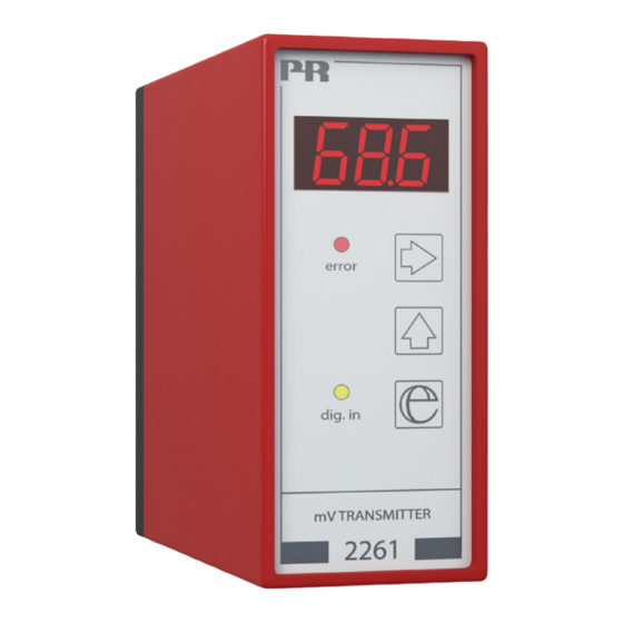
- Page 1 PERFORMANCE MADE SMARTER Product manual 2261 mV transmitter T E M P E R AT U R E I . S . I N T E R FA C E S CO M M U N I C AT I O N I N T E R FA C E S...
- Page 2 6 Product Pillars to meet your every need Individually outstanding, unrivalled in combination With our innovative, patented technologies, we make signal conditioning smarter and simpler. Our portfolio is composed of six product areas, where we offer a wide range of analog and digital devices covering over a thousand applications in industrial and factory automation.
-
Page 3: Table Of Contents
2261 Table of contents How to dismantle system 2200 ................ -
Page 4: How To Dismantle System 2200
How to dismantle system 2200 Picture 1: The back panel of the module is detached from the housing by way of a screwdriver. Picture 2: After this, the back panel can be pulled out together with the PCB, but please notice the position of the PCB as there is a number of different positions in the house. -
Page 5: Application
The 2261 converts bipolar mV signals from transducers supplied directly by the module to standard current / voltage signals. The 2261 is suitable for load cell applications. By way of the relative calibration function the scale can be tared, i.e. 0 and 100% calibrated without the need of the equivalent load. -
Page 6: Transducer Supply
Transducer supply Front-programmable to 5...13 VDC. It is up to the customer to ensure a max. load of 230 mA (e.g. 6 parallel 350 Ω load cells). Sense When the transducer supply is applied, the sense input can be used for compensation for cable resistance to the transducer. Electrical specifications Environmental conditions Operating temperature . - Page 7 Voltage output through internal shunt Signal range........0...10 VDC Min.
-
Page 8: Order
Order Type 2261 Hardware programming Output range MENU 4.3 0...10 mA 0...20 mA 0...500 mV 0...1000 mV 0...5 V 0...10 V Block diagram Supply + 24VDC V Excitation + Vreg Supply gnd. Sense 24 VDC Input + 0...20 D / A... -
Page 9: Routing Diagram
Routing diagram Programming If no buttons are pressed for a period of 2 minutes, display returns to stage 0.0 Memory 0 . 0 Go to entry menu / Leave menu without changes Taring Next digit or point If the key is pressed for a period > 2 sec. Change of parameter Press and hold , then press... -
Page 10: Programming / Operating The Function Keys
Programming / operating the function keys Documentation for routing diagram General The programming is menu-controlled. The main menus are numbered in level 0 (x.0), and the submenus are numbered in level 1 (x.1 to x.5). Each submenu has an accompanying entry menu. The menus are structured in such a way that the menus most frequently used are closer to the default menu 0.0. - Page 11 1.3 InO - Setting of overrange The analog output follows the set input span on a linear basis {1.1 - InL and 1.2 - InH} with a limit at 20.5 mA (normally approx. 103% input span). When the input signal is < or > the set input span, the display will track this and show -xx or xxx% until the input begins to limit.
- Page 12 5.0 APP - Application selection 5.1 tAR - Selection of taring type Possible selections are tLO - 0% taring enable, tHI - 100% taring enable, or dtA - taring disabled. If tLO is selected, activating the 3 key for more than 2 s or activating the digital input will tare the input signal to If tHI is selected, activating 3 for more than 2 s or activating the digital input will tare the input signal to 100% (max.).
-
Page 13: Document History
Document history The following list provides notes concerning revisions of this document. Rev. ID Date Notes 2232 UKCA added. 2261V103-UK... - Page 14 We are near you, all over the world Our trusted red boxes are supported wherever you are All our devices are backed by expert service and a 5-year business with a global reach. This means that we are warranty. With each product you purchase, you receive always nearby and know your local markets well.
- Page 15 Benefit today from PERFORMANCE MADE SMARTER PR electronics is the leading technology company specialized in making industrial process control safer, more reliable and more efficient. Since 1974, we have been dedicated to perfecting our core competence of innovating high precision technology with low power consumption.
Need help?
Do you have a question about the 2261 and is the answer not in the manual?
Questions and answers