Table of Contents
Advertisement
Quick Links
X-CREATE ANCHORING REQUIREMENTS
AND INSTRUCTIONS
X-CREATE SYSTEMS ARE HEAVY PIECES OF EQUIPMENT. THEY ARE INTENDED TO SUPPORT SIGNIFICANT
WEIGHT DURING ROUTINE USE AND SHOULD BE SECURELY ASSEMBLED AND FASTENED TO A SUPPORTING
SURFACE OF SUITABLE CONSTRUCTION. FAILURE TO TAKE PROPER CARE IN SITE SELECTION, ASSEMBLY OR
INSTALLATION CAN LEAD TO SERIOUS PERSONAL INJURY AND PROPERTY DAMAGE.
Electrical wires, water pipes etc. can be running underneath a floor so understand what is below before
drilling.
Read these instructions carefully before proceeding and follow the installation directions carefully to
minimize the risk of injury or property damage.
REVISION: A
Advertisement
Table of Contents

Related Manuals for Torque X-CREATE


Summary of Contents for Torque X-CREATE
- Page 1 X-CREATE ANCHORING REQUIREMENTS AND INSTRUCTIONS X-CREATE SYSTEMS ARE HEAVY PIECES OF EQUIPMENT. THEY ARE INTENDED TO SUPPORT SIGNIFICANT WEIGHT DURING ROUTINE USE AND SHOULD BE SECURELY ASSEMBLED AND FASTENED TO A SUPPORTING SURFACE OF SUITABLE CONSTRUCTION. FAILURE TO TAKE PROPER CARE IN SITE SELECTION, ASSEMBLY OR INSTALLATION CAN LEAD TO SERIOUS PERSONAL INJURY AND PROPERTY DAMAGE.
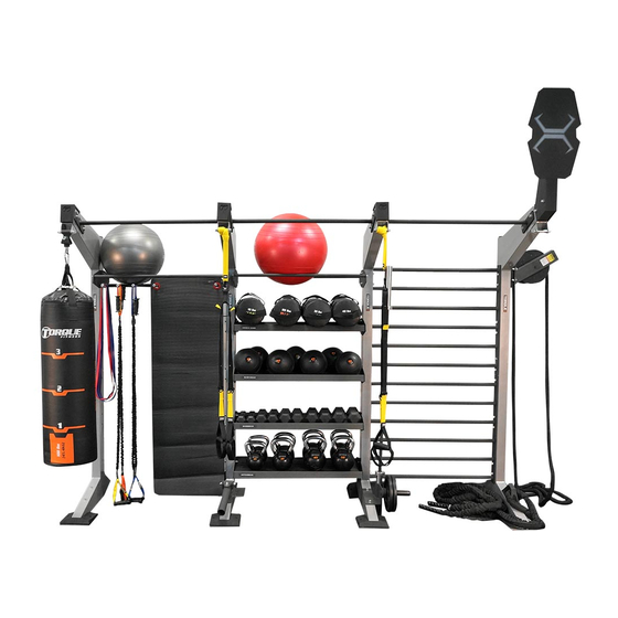
- Page 2 Thank you for your purchase of the Torque Fitness X-Create. The following information will help prepare your facility and installation provider for the delivery and installation of the selected X-Create configuration. SECURING Torque Fitness X-Create: X-Create configurations must be anchored directly to structurally sufficient concrete floors to ensure maximum safety and frame rigidity.
- Page 3 REQUIRED TOOLS AND HARDWARE FOR ANCHORING TO CONCRETE FLOORS Hammer Drill Socket Wrench and Socket ANSI Masonary drill bit (Reference anchors for correct size) 3/8” x 3” Concrete anchors 3/8” Washers Level...
- Page 4 (SEE STEP 4) NOTES 1. Complete assembly of entire frame and position the X-Create where desired prior to starting the anchoring procedure. Some attachments such as the lower Accessory Trays may interfere with the drilling operation and should be left off or removed prior to anchoring.
- Page 5 ANCHORING INSTRUCTIONS DIRECTIONS 1. Using an ANSI concrete drill bit (reference your hardware for the correct size), drill approximately a 3” hole (reference hardware for correct depth) through the anchoring hole in the base plate. (To prevent the drill from contacting the upright, place a piece of cardboard between the drill casing and the upright) 2.
- Page 6 Components securely to the frame. (Components may be difficult to assemble if the anchors are fully tightened.) 7. Tighten each anchor in every upright to the recommended torque specifications as listed in the specifications for the hardware being used. 8. Install the front and rear rubber boots on each upright using four socket head bolts and four washers.
- Page 7 ANCHORING DIMENSIONS FOR PLACEMENT ALONG WALL For most systems, the X-Create can be located so that the base is right against the wall. Only a small gap is needed between the wall and the rear base plate to allow room for the rubber boot.
- Page 8 BRIDGE SPACE SYSTEMS ANCHORING DIMENSIONS FOR BRIDGE SYSTEMS X-Create Bridge Systems are expandable in 2 foot increments. Shown above is the XCB- 2M-13 which is a 13 foot bridge system. The distance for B on this system is: B = 117.29 in (2979 mm) For longer Bridge Systems, simply add 24 inches (610 mm) per 2 foot increase in length to the B dimension.
Need help?
Do you have a question about the X-CREATE and is the answer not in the manual?
Questions and answers