Subscribe to Our Youtube Channel
Summary of Contents for Torque 21400
- Page 1 OPERATOR’S MANUAL NORBAR UNSUPPORTED CALIBRATION BEAMS Part Number 34110 | Issue 10 | Original Instructions (English)
-
Page 2: Table Of Contents
CONTENTS Part Numbers Covered by This Manual Matching Weight Sets Safety Introduction Features of Radius Ended Beams Features of Test Disc Scope of Use Equipment Required External Effects Temperature Compensation Gravitational Effects Buoyancy Effects Suggested Operating Procedure Interchange of Square Drive Repair and Recalibration of Beams Recalibration of Weights... -
Page 3: Part Numbers Covered By This Manual
Composite Beam Matching Weight Sets The weight sets listed below are designed to give specific torque ranges with each test beam. Individual weights are available from Norbar to create different torque ranges. These torques must be within the minimum and maximum applicable torques listed above. -
Page 4: Safety
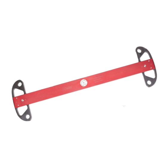
They are ideally suited to Norbar torque transducers, but can be employed on other manufacturer's equipment if certain constraints are met. See page 5 for more details. Torque is generated by the application of a known force at a known radius from the centre of rotation of the torque transducer. - Page 5 Norbar test beams are designed with square drives machined to the top limit of ISO2725:198. This minimises any play between the beam and the transducer. The use of commercially available adaptors may compromise this close fit and cause the beam to exceed the 8º limits mentioned above. In extreme cases the true centre of rotation may be altered, thus invalidating the calibration.
-
Page 6: Scope Of Use
SCOPE OF USE Most torque transducers having a female square drive can be calibrated using these test beams. The limitations are that: FIGURE 3 – End View Adaptors must not be used which extend the distance between the beam and the transducer. (See Figure 2), or which create excessive misalignment between the beam and transducer, (See Figure 3). -
Page 7: Equipment Required
EQUIPMENT REQUIRED The transducer must be fixed to a firm structure such that the reaction is taken without deflection of the structure. Norbar manufacture a pedestal, which when bolted to the ground, is suitable for calibrating torques up to 1000 N∙m or 1000 lbf∙ft. FIGURE 4 –... -
Page 8: External Effects
EXTERNAL EFFECTS Temperature Compensation Norbar test beams are manufactured from aerospace alloys. These materials have a higher expansion coefficient than steel and should therefore be used in a temperature controlled environment of 20˚C +/- 2˚C. If the beam must be used outside these limits, the temperature must be stable (within 1˚C change per hour) and the effective length of the beam calculated according to the details below. -
Page 9: Buoyancy Effects
Buoyancy Effects The Norbar system uses calibrated masses to generate a force downwards. It differs from mass balances where masses are compared like with like, because the masses are compared with a transducer. This means that Archimedes principle applies which means there is a force upwards on the masses caused by air pressure under them. -
Page 10: Suggested Operating Procedure
The transducer should be exercised by loading to full scale torque and back to zero three times. The display output should be watched during this process to avoid overloading. -
Page 11: Interchange Of Square Drive
When using the beam for calibration in accordance with BS 7882:1997 clause 4.6A Overload Test it is permitted to exceed the maximum torque of the beam and square by 8-12%. When frequently using ⅜” and ½” squares close to their maximum torque on Model No.s 21421, 21424 and 21425 these should be inspected and replaced periodically. -
Page 12: Repair And Recalibration Of Beams
REPAIR AND RECALIBRATION OF BEAMS Norbar Unsupported Calibration Beams are designed for transducer calibration at low levels of uncertainty. They are robust for normal handling by technicians, but if dropped or otherwise damaged, may lose their calibration integrity. It is therefore essential that the beam is recalibrated after any such incident. Recalibration involves establishing the beam length from the centre of the driving square to a locus of points on the beam end. - Page 13 NOTES...
- Page 14 Tel + 44 (0)1295 270333 Email enquiry@norbar.com To find your local For the most up-to-date Norbar company or version of the Operator’s distributor, please scan Manual, please scan the the QR code below. QR code below. www.norbar.com © Norbar Torque Tools Ltd 2021...


Need help?
Do you have a question about the 21400 and is the answer not in the manual?
Questions and answers