
Related Manuals for Banner SLLE14-280


Summary of Contents for Banner SLLE14-280
- Page 1 ® EZ-SCREEN LS Safety Light Screen Instruction Manual Original Instructions 179480 Rev. G 3 July 2018 © Banner Engineering Corp. All rights reserved 179480...
-
Page 2: Table Of Contents
1.1 Important . . . Read This Before Proceeding! ........................5 1.2 Use of Warnings and Cautions ............................5 1.3 EU Declaration of Conformity (DoC) ..........................5 1.4 Banner Engineering Corp Limited Warranty ........................6 1.5 Contact Us ..................................6 2 Standards and Regulations ............................. 8 2.1 Applicable U.S. - Page 3 ® EZ-SCREEN LS Safety Light Screen 6.4.2 FSD Interfacing Connections ..........................51 6.4.3 Machine Primary Control Elements and EDM Input .....................52 6.4.4 External Device Monitoring ..........................52 6.4.5 Fault Output ................................ 53 6.4.6 Scan Code Select ..............................53 6.4.7 Preparing for System Operation ..........................53 6.4.8 Sensor Interchangeability .............................53...
- Page 4 ® EZ-SCREEN LS Safety Light Screen 12.10 Alignment Aids ................................90 12.11 Snap-On Lens Shields ..............................90 12.12 Tubular Enclosures ..............................91 12.13 EZ-SCREEN LS Safety Light Screen in an IP69K Hygienic Housing ................91 ® ® 12.14 EZ-LIGHTS for EZ-SCREEN ...........................92 12.15 MSM Series Corner Mirrors ............................94...
-
Page 5: About This Document
These individuals are responsible to read and abide by these statements. 1.3 EU Declaration of Conformity (DoC) Banner Engineering Corp. herewith declares that the EZ-SCREEN LS is in conformity with the provisions of the Machinery Directive 2006/42/EC and all essential health and safety requirements have been met. -
Page 6: Banner Engineering Corp Limited Warranty
Banner Engineering Corp. warrants its products to be free from defects in material and workmanship for one year following the date of shipment. Banner Engineering Corp. will repair or replace, free of charge, any product of its manufacture which, at the time it is returned to the factory, is found to have been defective during the warranty period. This warranty does not cover damage or liability for misuse, abuse, or the improper application or installation of the Banner product. - Page 7 Email: brasil@bannerengineering.com Campos Elíseos, Jundiaí - SP, CEP.: 13208-761, Brasil China Address: Phone: +86 212 422 6888 www.bannerengineering.com Banner Engineering Shanghai Rep Office Website: Xinlian Scientific Research Building Level 12, Building 2 Email: sensors@bannerengineering.com.cn 1535 Hongmei Road, Shanghai 200233, China Japan...
-
Page 8: Standards And Regulations
2 Standards and Regulations The list of standards below is included as a convenience for users of this Banner device. Inclusion of the standards below does not imply that the device complies specifically with any standard, other than those specified in the Specifications section of this manual. -
Page 9: International/European Standards
® EZ-SCREEN LS Safety Light Screen 2.3 International/European Standards EN ISO 12100 Safety of Machinery – General Principles for EN 60204-1 Electrical Equipment of Machines Part 1: Design — Risk Assessment and Risk Reduction General Requirements ISO 13857 Safety Distances . . . Upper and Lower Limbs IEC 61496 Electro-sensitive Protection Equipment ISO 13850 (EN 418) Emergency Stop Devices, Functional IEC 60529 Degrees of Protection Provided by Enclosures... -
Page 10: Product Overview
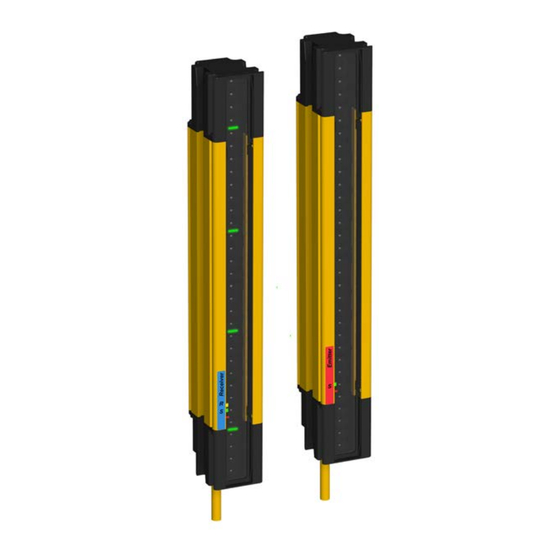
EZ-SCREEN LS Safety Light Screen shown without and with the optional EZLSA-K30LGR EZ-LIGHT Banner EZ-SCREEN LS is a two-piece (emitter and receiver), redundant, microprocessor-controlled, opposed-mode optoelectronic "light curtain" or "safety light screen". Models are available in 14 mm, 23 mm, or 40 mm resolution. Up to four pairs of SLLC.. -
Page 11: Appropriate Applications And Limitations
Ensure that all legal requirements have been met and that all technical installation and maintenance instructions contained in this manual are followed. The user has the sole responsibility to ensure that this Banner device is installed and interfaced to the guarded machine by Qualified Persons , in accordance with this manual and applicable safety regulations. -
Page 12: Control Reliability: Redundancy And Self-Checking
® EZ-SCREEN LS Safety Light Screen • As a tripping device to initiate or reinitiate machine motion (PSDI applications), unless the machine and its control system fully comply with the relevant standard or regulation (see OSHA 29CFR1910.217, ANSI/NFPA 79, ANSI B11.19, ISO 12100, IEC 60204-1, IEC 61496-1, or other appropriate standard) Reducing or If an EZ-SCREEN LS is installed for use as a perimeter guard (where a pass-through hazard may exist, see... - Page 13 ® EZ-SCREEN LS Safety Light Screen Description EZ-SCREEN LS Receiver EZ-SCREEN LS Emitter EZLSA-MBK-11 End-Cap Bracket Kit (four brackets) EZLSA-MBK-12 Center-Mount Bracket Kit (two brackets included for models with defined areas ≥ 980 mm) Test Rod (STP-13 for 14 mm models; STP-19 for 23 mm models; or STP-20 for 40 mm models) Literature packet with CD-ROM and Diagnostic Label Table 1: EZ-SCREEN LS Model Key Product Family Cascadable...
- Page 14 ® EZ-SCREEN LS Safety Light Screen Ordering Guide To order an EZ-SCREEN LS system, see Figure 3 on page 14: 1. Determine if the application calls for a stand-alone (single, non-cascade emitter and receiver pair) or if a cascade pair is to be used as a stand-alone and/or with multiple pairs to be ordered are part of a cascaded system. 2.
- Page 15 ® EZ-SCREEN LS Safety Light Screen To order a cascade system, see Figure 4 on page 15: 1. Determine the configuration of the first sensor pair (a stand-alone or the "Master" is connected to the machine control). 2. Determine the model from the applicable model number table. Model numbers listed in the tables are RD connection style model numbers.
- Page 16 Table 2: 10.1.2.1: EZ-SCREEN LS 14 mm Resolution Models (Standard/Stand-alone with RD connection) Recovery Time, Typ, OSSDs OFF to ON (ms) Response Time, Emitter Receiver Pair Defined Area Tr (ms) Non-sync beam All beams blocked blocked SLLE14-280 SLLR14-280 SLLP14-280 280 mm 11.6 SLLE14-350 SLLR14-350 SLLP14-350 350 mm 13.3 SLLE14-420 SLLR14-420 SLLP14-420 420 mm 15.0...
- Page 17 ® EZ-SCREEN LS Safety Light Screen Recovery Time, Typ, OSSDs OFF to ON (ms) Response Time, Emitter Receiver Pair Defined Area Tr (ms) Non-sync beam All beams blocked blocked SLLE23-420 SLLR23-420 SLLP23-420 420 mm SLLE23-490 SLLR23-490 SLLP23-490 490 mm 10.8 SLLE23-560 SLLR23-560 SLLP23-560...
- Page 18 ® EZ-SCREEN LS Safety Light Screen Recovery Time, Typ, OSSDs OFF to ON (ms) Response Time, Emitter Receiver Pair Defined Area Tr (ms) Non-sync beam All beams blocked blocked SLLE40-1050 SLLR40-1050 SLLP40-1050 1050 mm 11.2 SLLE40-1120 SLLR40-1120 SLLP40-1120 1120 mm 11.6 SLLE40-1190 SLLR40-1190...
- Page 19 ® EZ-SCREEN LS Safety Light Screen Recovery Time, Typ, OSSDs OFF to ON (ms) Response Time, Emitter Receiver Pair Defined Area Tr (ms) Non-sync beam All beams blocked blocked SLLCE14-1750 SLLCR14-1750 SLLCP14-1750 1750 mm 47.2 SLLCE14-1820 SLLCR14-1820 SLLCP14-1820 1820 mm 48.9 Table 6: 10.1.2.5: EZ-SCREEN LS 23 mm Resolution Models (Cascade with RD Connection) Recovery Time, Typ, OSSDs OFF...
-
Page 20: Replacement Parts
® EZ-SCREEN LS Safety Light Screen Recovery Time, Typ, OSSDs OFF to ON (ms) Response Time, Emitter Receiver Pair Defined Area Tr (ms) Non-sync beam All beams blocked blocked SLLCE40-560 SLLCR40-560 SLLCP40-560 560 mm SLLCE40-630 SLLCR40-630 SLLCP40-630 630 mm SLLCE40-700 SLLCR40-700 SLLCP40-700 700 mm... -
Page 21: Operating Features
WARNING: Use of Automatic Start/Restart (Trip Output) Application of power to the Banner device, the clearing of the sensing field, or the reset of an error condition must not initiate dangerous machine motion. Machine control circuitry must be designed so that one or more initiation devices must be engaged to start the machine (a conscious act), in addition to the Banner device entering Run mode. -
Page 22: Cascading
® EZ-SCREEN LS Safety Light Screen Figure 6. RD Connection with 8-wire Flying Lead Figure 7. RD Connection with Double-ended RD Figure 5. 300 mm Pigtail with M12/Euro-style QD Cordset Cordset 3.3.6 Cascading Up to four sensor pairs (any length or resolution) can be combined into one system. The cascade system automatically configures at power up when the terminator plug is installed (pre-installed from factory) or when a standard sensor pair or an interfacing cordset is used at the end of the series. -
Page 23: Interfacing An E-Stop Button Or Interlocking Switch
® EZ-SCREEN LS Safety Light Screen 3.3.8 Interfacing an E-Stop Button or Interlocking Switch EZ-SCREEN LS cascading models can connect electrical (hard) contacts from external devices, such as emergency stop buttons and interlocking switches, by using an RDLS-8..D cordset. The cascade input may be used to monitor emergency stop buttons, interlocked gates, or guards and meets or exceeds the requirements for OSHA/ANSI control reliability and up to Category 4 PLe, per ISO 13849-1. -
Page 24: Specifications
® EZ-SCREEN LS Safety Light Screen 4 Specifications 4.1 General Specifications Supply Current (mA) Supply Voltage at the Device 24 V dc ±15% (use a SELV-rated power supply according to EN IEC 60950). Emitter Receiver* The external voltage supply must be capable of buffering brief mains interruptions of 20 ms, as specified in IEC/EN 60204-1. -
Page 25: Receiver Specifications
® EZ-SCREEN LS Safety Light Screen 4.2 Receiver Specifications Response Time Output Signal Switching Devices (OSSDs) Dependent on the number of sensing beams; for the response time, see Two redundant solid-state 24 V dc, 0.5 A max. sourcing OSSD Models Tables on page 16 (Output Signal Switching Device) safety outputs (Use optional interface solutions for ac or larger dc loads) -
Page 26: Dimensions
® EZ-SCREEN LS Safety Light Screen 4.4 Dimensions End Brackets Mounted Outward End Bracket with EZ-LIGHT *Add 35 mm to L2 value to End Brackets Mounted Inward determine overall mounting length Approx. 35.0 * [1.38] Hole to Hole Length with Hole to Hole Length with Defined Area 3 (mm) Emitter/Receiver Model... - Page 27 ® EZ-SCREEN LS Safety Light Screen Hole to Hole Length with Hole to Hole Length with Defined Area 3 (mm) Emitter/Receiver Model Housing Length (L1) Brackets Out (L2) (mm) Brackets In (L3) (mm) SLL...-630… 634 mm (25.0 in) 676.1 618.1 SLL...-700…...
-
Page 28: Mechanical Installation
Ensure that all legal requirements have been met and that all technical installation and maintenance instructions contained in this manual are followed. The user has the sole responsibility to ensure that this Banner device is installed and interfaced to the guarded machine by Qualified Persons , in accordance with this manual and applicable safety regulations. - Page 29 ® EZ-SCREEN LS Safety Light Screen Hard (fixed) Guarding Hard (fixed) Guarding Robot Turn- Table Safety Light Curtain/Screen Nearest Hazard Point Reset Switch Figure 13. Safety distance (minimum distance) and hard (fixed) guarding Formula and Examples U.S. Applications European Applications The Safety (Separation) Distance formula for U.S.
-
Page 30: Reducing Or Eliminating Pass-Through Hazards
® EZ-SCREEN LS Safety Light Screen Notes: 1. The OSHA-recommended hand speed constant K has been determined by various studies and, although these studies indicate speeds of 1600 mm/sec. (63 in/sec.) to more than 2500 mm/sec. (100 in/sec.), they are not conclusive determinations. Consider all factors, including the physical ability of the operator, when determining the value of K to be used. -
Page 31: Supplemental Safeguarding
WARNING: Use of the Banner device for Access or Perimeter Guarding If a Banner device is installed in an application that results in a pass-through hazard (for example, perimeter guarding), either the Banner device or the Machine Primary Control Elements (MPCEs) of the guarded machine must cause a Latched response following an interruption of the defined area. -
Page 32: Adjacent Reflective Surfaces
® EZ-SCREEN LS Safety Light Screen The reset switch must be mounted at a location that complies with the warning and guidelines below. If any hazardous areas are not in view from the switch location, additional means of safeguarding must be provided. The switch should be protected from accidental or unintended actuation (for example, through the use of rings or guards). -
Page 33: Use Of Corner Mirrors
® EZ-SCREEN LS Safety Light Screen Do not position reflective surfaces within the shaded area At the midpoint of the defined area, a test piece (represented by the darker sircle) with the specified system resolution does not cause a blocked condition, due to an optical short circuit. -
Page 34: Emitter And Receiver Orientation
® EZ-SCREEN LS Safety Light Screen Table 10: SSM and MSM Series Glass-Surface Mirrors—Maximum Emitter and Receiver Separation Number of Corner Mirrors Max. Emitter / Receiver Separation 11.0 m (36 ft) 10.1 m (33 ft) 9.3 m (30.5 ft) 8.6 m (28 ft) www.bannerengineering.com See the specific mirror data sheet or for more information. -
Page 35: Installation Of Multiple Systems
® EZ-SCREEN LS Safety Light Screen Receiver Emitter Receiver Receiver Emitter Emitter Both cable ends down Both cable ends up Orientation parallel to floor with both cable ends pointing in the same direction Figure 17. Examples of Correct Emitter/Receiver Orientation Receiver Receiver Emitter... -
Page 36: Mounting System Components
® EZ-SCREEN LS Safety Light Screen Receiver Receiver Scan Code 1 Emitter Scan Code 1 Emitter Receiver Emitter Scan Code 2 Scan Code 2 Receiver Emitter b. Two or three systems stacked (or alternate receiver/ a. Two systems in a horizontal plane emitter positions) Receiver 3 Emitter... -
Page 37: Mounting The End-Mount Brackets
® EZ-SCREEN LS Safety Light Screen Each sensor ships with two EZLSA-MBK-11 end-mount brackets. Emitters and receivers 980 mm and longer also include one EZLSA-MBK-12 center-mount bracket. The supplied end-mount brackets allow ±23° rotation, can be mounted with flange out or flange in, and in 90° increments. EZLSA-MBK-12 center-mount brackets allow 30° rotation in one direction and 15°... -
Page 38: Mounting The Center- And Side-Mount Brackets
® EZ-SCREEN LS Safety Light Screen 5.2.3 Mounting the Center- and Side-Mount Brackets Sensor Mounting and Mechanical Alignment • page 39 for additional mounting recommendations. EZLSA-MBK-11 • The machine interface connector ends of both sensors End Mount Bracket must point in the same direction. •... -
Page 39: Sensor Mounting And Mechanical Alignment
® EZ-SCREEN LS Safety Light Screen • Mounting the Center- and Side-Mount Brackets Figure 22. Optional Side-Mount Bracket on page 38 for the general mounting procedure. • Sensor Mounting and Mechanical Alignment page 39 for additional mounting recommendations. • The machine interface connector ends of both sensors must point in the same direction. -
Page 40: Mounting Dimensions
® EZ-SCREEN LS Safety Light Screen Angled or Horizontal Installations – verify that: Vertical Installations – verify that: • Distance X at the emitter and receiver are equal • Distance X at the emitter and receiver are equal • Distance Y at the emitter and receiver are equal •... - Page 41 ® EZ-SCREEN LS Safety Light Screen Center-Mount Brackets Dimensions Figure 25. EZLSA-MBK-12 Side-Mount Brackets Dimensions Figure 26. EZLSA-MBK-16 www.bannerengineering.com - Tel: +1.763.544.3164...
-
Page 42: Electrical Installation And Testing
Ensure that all legal requirements have been met and that all technical installation and maintenance instructions contained in this manual are followed. The user has the sole responsibility to ensure that this Banner device is installed and interfaced to the guarded machine by Qualified Persons , in accordance with this manual and applicable safety regulations. -
Page 43: Initial Electrical Connections
SCREEN LS when the supply is operating at +20 V dc. Values in the previous table are worse case. Contact banner Engineering if there are any questions. Note: The length of Emitter machine interface cordsets can be two times longer than those listed for the receiver in the table above if a CSB Splitter cordset is not used. -
Page 44: Configuring The System For Initial Checkout
® EZ-SCREEN LS Safety Light Screen • Ensure proper System function whenever any maintenance or modification is performed on the System or on the machinery that is guarded by the System. 6.3.1 Configuring the System for Initial Checkout For the initial checkout, the EZ-SCREEN LS System must be checked without power available to the guarded machine. Final interface connections to the guarded machine cannot take place until the light screen system has been checked out. - Page 45 ® EZ-SCREEN LS Safety Light Screen Straight Edge Indicator LEDs All OFF Straight Edge Note: At power-up, all indicators are tested (flash), then the Scan Code is displayed. 2. Turn on the power to the emitter and receiver. If the Channel #1 beam is not aligned, the Status and Alignment indicator 1 will be red, the Run mode indicator will be off, and the 7-segment display sequentially indicates CH1.
-
Page 46: Optical Alignment Procedure With Mirrors
Note: A LAT-1-SS Laser Alignment Tool is very helpful by providing a visible red dot along the optical axis. Figure 27 57477 on page 46 and Banner Safety Applications Note SA104 (p/n ) for further information. Component 2 (Mirror) - Page 47 ® EZ-SCREEN LS Safety Light Screen (with power OFF) and replaced by the terminator plug, an EZ-LIGHT (integral or remotely mounted), or an Emergency Stop/ Interlocking switch via a RDLS-8..D cordset. Programming Key Switch Location The EZA-RBK-1 or an SPDT (Form C) switch is required to perform the remote programming procedure, as shown. A key- actuated switch provides some supervisory control since the key can be removed from the switch.
- Page 48 ® EZ-SCREEN LS Safety Light Screen Action Indication Comments Turn the programming key switch to the EZA-RBK-1 LED: ON (key in Program This teaches and saves the new fixed Program position (clockwise) position), then slowly flashes for blanking configuration. momentarily (> 0.25 second) and then approximately 5 seconds after the key return to the Run position.
-
Page 49: Trip Test
® EZ-SCREEN LS Safety Light Screen Action Indication Comments Ensure that the programming key switch EZA-RBK-1 LED: rapid flashing, and All LEDs turn on momentarily during the is in the Run position and reapply power then OFF Power-up Display Test Sequence. to the EZ-SCREEN LS system. -
Page 50: Electrical Connections To The Guarded Machine
• Scan Code Select CAUTION: Shock Hazard Always disconnect power from the Banner device and the guarded machine before making any connections or replacing any component. Use extreme caution to avoid electrical shock at all times. 6.4.1 OSSD Output Connections Refer to the output specifications in the Receiver Specifications and these warnings before making OSSD output connections and interfacing the EZ-SCREEN LS to the machine. -
Page 51: Fsd Interfacing Connections
Failure to follow these instructions could result in serious injury or death. WARNING: OSSD Interfacing To ensure proper operation, the Banner device output parameters and machine input parameters must be considered when interfacing the Banner device OSSD outputs to machine inputs. Machine control circuitry must be designed so that the maximum load resistance value is not exceeded and that the maximum specified OSSD Off-state voltage does not result in an On condition. -
Page 52: Machine Primary Control Elements And Edm Input
® EZ-SCREEN LS Safety Light Screen each other, and are directly connected to each other; or where the possibility of such a failure can be excluded. If this cannot be achieved, then dual-channel control should be used. Methods to exclude the possibility of these failures include, but are not limited to: •... -
Page 53: Fault Output
2 (Orn/Blk) will not be monitored and could result in undetected faults and create an unsafe condition, which could result in serious bodily injury or death. If there are any questions concerning retrofit installations, contact Banner Engineering. 6.4.5 Fault Output The current sourcing (PNP) solid-state output (70 mA maximum) is used for control functions that are not safety related;... -
Page 54: Wiring Diagrams
® EZ-SCREEN LS Safety Light Screen To use this option, connect all emitter wires in parallel (color-for-color) to the receiver cable via individual wires or the CSB.. splitter cordset (can be used with only emitters and receivers with similar connectors, such as a pair with 8-pin quick disconnects or a pair with 5-pin quick disconnects.). -
Page 55: Generic Wiring Diagram-5-Pin Receiver And Um-Fa
® EZ-SCREEN LS Safety Light Screen * All pins shown as no connection (n.c.) are either not connected or are paralleled to same color wire from the receiver cable. ** Scan Code 1: not connected or connected to 0 V dc (as shown). Scan Code 2: connect to 24 V dc. 6.5.3 Generic Wiring Diagram—5-pin Receiver and UM-FA-..A Safety Module +24V dc 0V dc... -
Page 56: Generic Wiring Diagram-5-Pin Receiver And Safety Module/Controller Or Safety Plc/Pes
® EZ-SCREEN LS Safety Light Screen 6.5.4 Generic Wiring Diagram—5-pin Receiver and Safety Module/Controller or Safety PLC/PES +24Vdc 0Vdc Bn (Pin #1) 5-pin male XS/SC26-2xx Euro-style XS2so or XS4so (face view) +24Vdc 0Vdc Gn/Ye (#5) FSD1 SO1a Bu (#3) (SO1 not split) Bk (#4) FSD2 SO1b... -
Page 57: Generic Wiring Diagram-8-Pin Receiver And Redundant Fsds
® EZ-SCREEN LS Safety Light Screen 6.5.5 Generic Wiring Diagram—8-pin Receiver and Redundant FSDs +24V dc 0V dc 8-pin male M12/Euro-style Bn (Pin #1) +24V dc (face view) Gn/Ye (#7) Ground Bu (#6) 0V dc Bk (#5) OSSD1 FSD1 Wh (#4) OSSD2 FSD2 Vi (#8) -
Page 58: Generic Wiring Diagram-8-Pin Receiver And Im-T-9A Interface Module
** Scan Code 1: not connected or connected to 0 V dc (as shown). Scan Code 2: connect to 24 V dc. *** Other interfacing modules and solutions available. See the Banner Engineering catalog or website for more information. Note: See the IM-T-..A module datasheet (p/n 62822 ) for complete installation instructions. -
Page 59: System Operation
® EZ-SCREEN LS Safety Light Screen 7 System Operation 7.1 Security Protocol Certain procedures for installing, maintaining, and operating the EZ-SCREEN LS must be performed by either Designated Persons or Qualified Persons. A Designated Person is identified and designated in writing, by the employer, as being appropriately trained and qualified to perform system resets and the specified checkout procedures on the EZ-SCREEN LS. - Page 60 ® EZ-SCREEN LS Safety Light Screen Run Mode Alignment Operating Mode Status Indicator 7-Segment Diagnostic Display OSSD Outputs Indicators 9 Indicator Alignment Mode - Alignment 1 Red, Beam 1 Blocked Others Off Alignment Mode - Red or Green Total number of blocked beams Beam 1 Clear Solid Green or Flashing Run Mode - Clear...
-
Page 61: Normal Operation
® EZ-SCREEN LS Safety Light Screen Cascade Powered Up Clear Object is Blocking Light Screen #4 Object is Blocking Light Screen #3 Display: # of beams Display: Display: blocked OSSDs: On OSSDs: On OSSDs: Off Run Mode: On Run Mode: On Run Mode: On Status: Green Status: Green... - Page 62 ® EZ-SCREEN LS Safety Light Screen Note: Verify Proper Operation The EZ-SCREEN LS can operate as it is designed only if it and the guarded machine are operating properly, both separately and together. It is the user’s responsibility to verify this, on a regular basis, as Checkout Procedures instructed in on page 63.
-
Page 63: Checkout Procedures
WARNING: Do Not Use Machine Until System Is Working Properly If all of these checks cannot be verified, do not attempt to use the safety system that includes the Banner device and the guarded machine until the defect or problem has been corrected. Attempts to use the guarded machine under such conditions could result in serious injury or death. - Page 64 17. Test the machine stopping response time, using an instrument designed for that purpose, to verify that it is the same or less than the overall system response time specified by the machine manufacturer. A Banner Applications Engineer can recommend a suitable instrument.
-
Page 65: Troubleshooting
WARNING: Shut Down Machinery Before Servicing The machinery to which the Banner device is connected must not be operating at any time during major service or maintenance. This may require lockout/tagout procedures (refer to OSHA1910.147, ANSI Z244-1, ISO 14118 or the appropriate standard for controlling hazardous energy). - Page 66 ® EZ-SCREEN LS Safety Light Screen Diagnostic Error Description Cause of Error and Appropriate Action Display Recovery Procedures Receiver Error • Cycle power, on page 65. • If the error clears, perform a Daily Checkout procedure (per This error can occur due to EZ-SCREEN Checkout Procedures: Shift and Daily Checkout either excessive electrical noise Procedure;...
-
Page 67: Emitter Error Codes
® EZ-SCREEN LS Safety Light Screen Diagnostic Error Description Cause of Error and Appropriate Action Display Recovery Procedures Excessive Noise Error – • Cycle power (see on page 65). Cascade Input • If the error clears, perform the daily checkout procedure (per EZ-SCREEN Checkout Procedures: Shift and Daily Checkout This error can occur due to Procedure;... -
Page 68: Checking For Sources Of Electrical Noise
EZ-SCREEN LS System. It is good wiring practice (and may be required by code) to isolate EZ-SCREEN LS wires from high-voltage wires. 1. Use the Banner model BT-1 Beam Tracker Alignment Aid (see Accessories on page 80) to detect electrical transient spikes and surges. -
Page 69: Maintenance
10.2 Warranty Service Contact Banner Engineering for troubleshooting of this device. Do not attempt any repairs to this Banner device; it contains no field-replaceable parts or components. If the device, device part, or device component is determined to be defective by a Banner Applications Engineer, they will advise you of Banner's RMA (Return Merchandise Authorization) procedure. -
Page 70: Cascadeable Ez-Screen Ls
® EZ-SCREEN LS Safety Light Screen 11 Cascadeable EZ-SCREEN LS 11.1 Overview of Cascading EZ-SCREEN LS emitters and receivers are available in cascadeable models. These models can be used as stand-alone light screens, or can be cascaded up to four pairs in one system. The cascaded sensor pairs can be any length, any number of beams, or have different resolutions (14 mm, 23 mm, and 40 mm), as long as each emitter matches its receiver. -
Page 71: System Components And Specifications
11.2 Determining Interconnect Cordset Lengths The following cordset length charts are possible combinations for each side of example cascaded systems. Model DELS-11...E cordsets are used for calculations. Other lengths and combinations are possible; call Banner Engineering for assistance. Figure 44. Cascade Cordset Connection As the machine interface cordset lengthens, the voltage available at the first (master) sensor pair decreases, which results in shorter possible interconnect cordsets to maintain supply voltage requirements at last cascaded sensor. - Page 72 SCREEN LS when the supply is operating at +20 V dc. Values in the previous table are worse case. Contact banner Engineering if there are any questions. Note: The length of Emitter machine interface cordsets can be two times longer than those listed for the receiver in the table above if a CSB Splitter cordset is not used.
-
Page 73: Response Time For Cascaded Light Screens
WARNING: Improper Installation Failure to follow the installation guidelines and procedures could result in the ineffective or non-operation of the Banner device that could create an unsafe condition resulting in serious injury or death. 11.3.1 Determining System Response Time If the safety distance does not need to be optimized (at a minimum), simply add 6 ms to the response time of the receiver... -
Page 74: Individual Response Time And Safety (Minimum) Distance
® EZ-SCREEN LS Safety Light Screen 11.3.2 Individual Response Time and Safety (Minimum) Distance When calculating individual safety distance for each emitter/receiver pair, the pair’s position in the cascade affects its Calculating the Safety Distance response time, which then affects its safety distance (see safety distance formulas in (Minimum Distance) on page 28). -
Page 75: E-Stop Switch Requirements (Positive-Opening)
® EZ-SCREEN LS Safety Light Screen The CSSI input is a two-channel (4-wire) input such that the redundant channels must be in the same state (either open or closed). The CSSI input can be connected to hard/relay contacts per requirements. The simultaneity between the two contacts, on opening and closing, is 3 seconds. -
Page 76: Interlock Switches In Cascaded Systems
The Cascade input may be used to monitor interlock safety gates or guards. Requirements vary widely for the level of control reliability or safety category (per ISO 13849-1) in the application of interlocked guards. While Banner Engineering recommends the highest level of safety in any application, the user is responsible to safely install, operate, and maintain Figure 47 each safety system, and comply with all relevant laws and regulations. -
Page 77: Positive-Opening Interlocking Safety Switches
® EZ-SCREEN LS Safety Light Screen The guard must be located at an adequate distance from the danger zone (so the hazard has time to stop before the guard is opened sufficiently to provide access to the hazard), and it must open either laterally or away from the hazard, not into the safeguarded area. -
Page 78: Remote Teach Fixed Blanking (Wiring)
® EZ-SCREEN LS Safety Light Screen Open NOTE: This application is considered to meet or exceed requirements for OSHA/ANSI control reliability and Category 4 per ISO13849-1. EZ-SCREEN LS RDLS-8..D Take precautions to prevent unused wires from RDLS-8..D Pinout shorting to ground or to other sources of Brown Ch1a energy (for example, terminate with wire-nut). - Page 79 ® EZ-SCREEN LS Safety Light Screen EZ-SCREEN LS RDLS-8..D Program www.bannerengineering.com - Tel: +1.763.544.3164...
-
Page 80: Accessories
® EZ-SCREEN LS Safety Light Screen 12 Accessories 12.1 Cordsets Machine interface cordsets provide power to the first emitter/receiver pair. Sensor interconnect cables provide power to subsequent emitters and receivers in the cascade. Cordsets typically have yellow PVC cables and black overmolds. A removable disconnect (RD) is required to connect directly to the sensor housing. -
Page 81: Single-Ended (Machine Interface) Cables
M12/Euro-style quick disconnect (models ending in P5). These cordsets have a M12/Euro-style QD connector on one end and are unterminated (cut to length) on the other end to interface with guarded machine. PVC jacketed overmold and cables. Model Length Banner Cordset Pinout/Color Code M12 Connector (female face view) Color... -
Page 82: Double-Ended (Sensor Interconnect) Cordsets
DEE2R-8..D 8-pin M12/Euro-style QD to M12/Euro-style QD (female-male) cordsets—Use the DEE2R-8... cordsets to extend the length of cordsets and directly connect to other devices with an 8-pin M12/Euro-style quick disconnect. Other lengths are available. Model Length Banner Cordset Pinout/Color Code M12 Connector (female face view) DEE2R-81D 0.3 m (1 ft) - Page 83 DEE2R-5..D 5-pin M12/Euro-style QD to M12/Euro-style QD (female-male) cordsets—Use the DEE2R-5... cordsets to extend the length of cordsets and directly connect to other devices with a 5-pin M12/Euro-style quick disconnect. Other lengths are available. Model Length Banner Cordset Pinout/Color Code M12 Connector (female face view) DEE2R-51D 0.3 m (1 ft)
- Page 84 LS Safety Light Screen DELSE-..1D RD to M12/Euro-style QD (male) cordsets—Use DELSE-..1D cordsets to create or replace a 300 mm pigtail M12/Euro-style quick disconnect (models ending in P8 or P5). Model Length Banner Cordset Pinout/Color Code Emitter Receiver Color Function...
-
Page 85: Splitter Cordsets
DELSEF-4..D 4-pin RD to M12/Euro-style QD (female) cordsets—Use DELSEF-4..D cordsets for connecting one or two-color EZ-LIGHTs ® ® EZ-LIGHTS for EZ-SCREEN or other indicators (see on page 92 for list of EZ-LIGHTS). Model Length Banner Cordset Pinout/Color Code DELSEF-40D 0.07 m (0.2 ft) Color Function DELSEF-41D 0.3 m (1 ft) Brown OSSD OFF/FAULT... -
Page 86: Bulkhead Connector
13.0 mm 7.0 mm (0.51") (0.28") 8-pin Euro-style female connector 3 m PMEF-810D (10 ft) wires, cut to length (Banner color code); 22 AWG/0.33 mm² 1/4-18NPT M12 x 1 O-Ring 12.2 AC Interface Boxes The AC interface box is for use with EZ-SCREEN LS emitters and/or receivers. EZAC-R..A models can supply +24 V dc to one EZ-SCREEN LS receiver, a single emitter-receiver pair, or up to three cascaded emitter/receiver pairs. -
Page 87: Universal (Input) Safety Modules
IM-T-..A interface modules provide forced-guided, mechanically-linked relay (safety) outputs for the EZ-SCREEN LS System with an 8-pin interconnect (with EDM function). The IM-T-..A interface module is required to be monitored by the EDM function and should not be used with EZ-SCREEN LS with a 5-pin interconnection (P5). See Banner datasheet p/n 62822 for more information. -
Page 88: Contactors
If used, two contactors per EZ-SCREEN LS System that are monitored by the EDM circuit are required and should not be 111881 used with the EZ-SCREEN LS with a 5-pin interconnection (P5) model. See Banner datasheet p/n for more information. - Page 89 ® EZ-SCREEN LS Safety Light Screen Adjust clamp screw to loosen or tighten clamp. ROTATION ADJUSTMENT front clamp screw EZ-SCREEN light screen clamp clamp screw Slide inner bracket assembly into outer (max. torque 15 in-lbs) bracket groove. rotation position screw (max.
-
Page 90: Remote Blanking Key Switch Box
® EZ-SCREEN LS Safety Light Screen 12.9 Remote Blanking Key Switch Box Use the remote blanking key switch box to configure fixed blanking remotely on cascadeable model receivers. The DELSEF-81D cordset interfaces with the receiver cascade end and the DEE2R-8..D cordset provides the required extension as needed. Model Description Remote Blanking Key Switch. -
Page 91: Tubular Enclosures
® EZ-SCREEN LS Safety Light Screen 12.12 Tubular Enclosures The tubular enclosures include stainless mounting brackets and hardware and are: • Ideal for high-pressure wash-down environments • Made of clear FDA-grade polycarbonate tubing with acetal end caps • Rated IEC IP67/IP69K Using enclosures affects the sensing range of the emitter/receiver used: when in pairs, the range can be reduced by 30%. -
Page 92: Ez-Lights ® For Ez-Screen
® EZ-SCREEN LS Safety Light Screen ® ® 12.14 EZ-LIGHTS for EZ-SCREEN Provides clear, 360° indication of the of the EZ-SCREEN receiver's output status and receiver lockouts. EZ-LIGHT or other means of indication must draw less than 100 mA at 24 V dc. Figure 52. - Page 93 ® EZ-SCREEN LS Safety Light Screen Standard Receivers (SLLR..-….P8)—Use with a CSB-M128..M1281 splitter cable and optional DEE2R-8..D double-ended cables. Use only 121901 EZ-LIGHT models with the suffix "8PQ8" when connecting to the machine interface connection. See datasheet p/n for more information.
-
Page 94: Msm Series Corner Mirrors
® EZ-SCREEN LS Safety Light Screen Cascade Receivers (SLLCR..-….)—Use a DELSEF-4..D RD-to-M12/Euro-style QD (4-pin) and optional DEE2R-5..D double-ended cables for remotely locating the EZ-LIGHT, or a EZLSA-K30LGR can be mounted directly to the CSSI connector. Model Construction Connection LED Function •... -
Page 95: Msa Series Stands
® EZ-SCREEN LS Safety Light Screen Mirror Defined Area Reflective Area Y Mounting 1 Mounting L2 Model 17 Length SSM-200 150 mm (5.9 in) 200 mm (7.9 in) 278 mm (10.9 in) 311 mm (12.2 in) SSM-375 300 mm (11.8 in) 375 mm (14.8 in) 486 mm (19.1 in) 453 mm (17.8 in) -
Page 96: Glossary
® EZ-SCREEN LS Safety Light Screen 13 Glossary ANSI (American National Standards Institute) Auto Start/Restart (Trip) Condition Acronym for the American National Standards The safety outputs of a safety light screen system Institute, an association of industry representatives turn off when an object completely blocks a beam. In that develops technical standards (including safety an Auto Start/Restart condition, the safety outputs standards). - Page 97 Final Switching Device (FSD) permitted; failures which cause an unsafe condition The component of the machine’s safety-related (a failure to danger) are not. Banner safety products control system that interrupts the circuit to the are extensively FMEA tested. machine primary control element (MPCE) when the output signal switching device (OSSD) goes to the OFF-state.
- Page 98 ® EZ-SCREEN LS Safety Light Screen Lockout Condition A safety light screen condition that is automatically attained in response to certain failure signals (an internal lockout). When a Lockout condition occurs, the safety light screen’s safety outputs turn Off; the failure must be corrected and a manual reset is required to return the system to Run mode.
- Page 99 (after the operation) by the operator. PSDI is commonly confused with "Trip Initiate." PSDI is defined in OSHA CFR1910.217. Banner safety light screen systems may not be used as PSDI devices on mechanical power presses, per OSHA regulation 29 CFR 1910.217.
- Page 100 When inserted into the defined area Banner safety light screen systems and safety and placed in front of a beam, the test piece causes modules are self-checking.
Need help?
Do you have a question about the SLLE14-280 and is the answer not in the manual?
Questions and answers