
Subscribe to Our Youtube Channel
Related Manuals for Banner SLLVE23-350


Summary of Contents for Banner SLLVE23-350
- Page 1 ® EZ-SCREEN LS Basic Safety Light Screen Instruction Manual Original Instructions 204120 Rev. A 4 January 2018 © Banner Engineering Corp. All rights reserved 204120...
-
Page 2: Table Of Contents
1.1 Important . . . Read This Before Proceeding! ........................4 1.2 Use of Warnings and Cautions ............................4 1.3 EU Declaration of Conformity (DoC) ..........................4 1.4 Banner Engineering Corp Limited Warranty ........................4 1.5 Contact Us ..................................5 2 Standards and Regulations ............................. 7 2.1 Applicable U.S. - Page 3 ® EZ-SCREEN LS Basic Safety Light Screen 6.4.6 Scan Code Select ..............................42 6.4.7 Preparing for System Operation ..........................42 6.4.8 Sensor Interchangeability .............................42 6.5 Wiring Diagrams ................................43 6.5.1 Reference Wiring Diagrams ..........................43 7 System Operation ..............................49 7.1 Security Protocol ................................49 7.2 Status Indicators ................................
-
Page 4: About This Document
Banner Engineering Corp. warrants its products to be free from defects in material and workmanship for one year following the date of shipment. Banner Engineering Corp. will repair or replace, free of charge, any product of its manufacture which, at the time it is returned to the factory, is found to have been defective during the warranty period. This warranty does not cover damage or liability for misuse, abuse, or the improper application or installation of the Banner product. -
Page 5: Contact Us
PURPOSE), AND WHETHER ARISING UNDER COURSE OF PERFORMANCE, COURSE OF DEALING OR TRADE USAGE. This Warranty is exclusive and limited to repair or, at the discretion of Banner Engineering Corp., replacement. IN NO EVENT SHALL BANNER ENGINEERING CORP. BE LIABLE TO BUYER OR ANY OTHER PERSON OR ENTITY FOR ANY... - Page 6 ® EZ-SCREEN LS Basic Safety Light Screen China Address: Phone: +86 212 422 6888 Banner Engineering Shanghai Rep Office Website: www.bannerengineering.com Xinlian Scientific Research Building Level 12, Building 2 Email: sensors@bannerengineering.com.cn 1535 Hongmei Road, Shanghai 200233, China Japan Address: Phone: +81 (0)6 6309 0411 www.bannerengineering.com...
-
Page 7: Standards And Regulations
2 Standards and Regulations The list of standards below is included as a convenience for users of this Banner device. Inclusion of the standards below does not imply that the device complies specifically with any standard, other than those specified in the Specifications section of this manual. -
Page 8: International/European Standards
® EZ-SCREEN LS Basic Safety Light Screen 2.3 International/European Standards EN ISO 12100 Safety of Machinery – General Principles for EN 60204-1 Electrical Equipment of Machines Part 1: Design — Risk Assessment and Risk Reduction General Requirements ISO 13857 Safety Distances . . . Upper and Lower Limbs IEC 61496 Electro-sensitive Protection Equipment ISO 13850 (EN 418) Emergency Stop Devices, Functional IEC 60529 Degrees of Protection Provided by Enclosures... -
Page 9: Product Overview
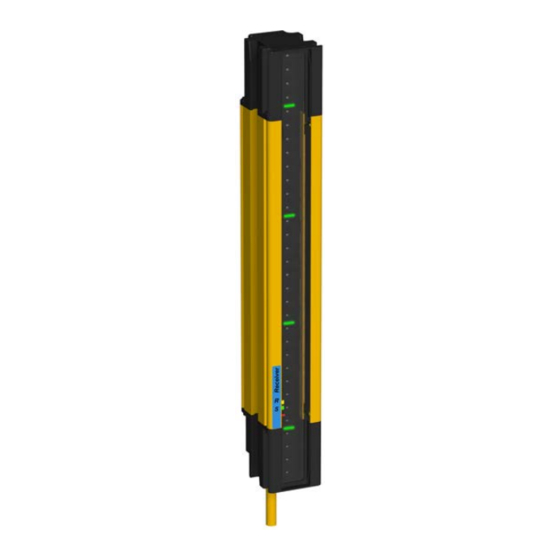
3 Product Overview EZ-SCREEN LS Basic Safety Light Screen Banner EZ-SCREEN LS Basic is a two-piece (emitter and receiver), redundant, microprocessor-controlled, opposed-mode optoelectronic "light curtain" or "safety light screen". Models are available in 23 mm resolution. Emitters have a row of synchronized modulated infrared (invisible) light-emitting diodes (LEDs) in a robust, compact metal housing. -
Page 10: Appropriate Applications And Limitations
Ensure that all legal requirements have been met and that all technical installation and maintenance instructions contained in this manual are followed. The user has the sole responsibility to ensure that this Banner device is installed and interfaced to the guarded machine by Qualified Persons , in accordance with this manual and applicable safety regulations. -
Page 11: Control Reliability: Redundancy And Self-Checking
® EZ-SCREEN LS Basic Safety Light Screen If an EZ-SCREEN LS Basic is installed for use as a perimeter guard (where a pass-through hazard may exist, see Reducing or Eliminating Pass-Through Hazards on page 22), the dangerous machine motion can be initiated by normal means only after the safeguarded area is clear of individuals and the safety related part of the control system that is providing the latching function has been manually reset. - Page 12 Table 2: EZ-SCREEN LS Basic23 mm Resolution Models Recovery Time, Typ, OSSDs OFF to ON (ms) Response Time, Emitter Receiver Pair Defined Area Tr (ms) Non-sync beam All beams blocked blocked SLLVE23-350 SLLVR23-350 SLLVP23-350 350 mm SLLVE23-420 SLLVR23-420 SLLVP23-420 420 mm SLLVE23-630 SLLVR23-630 SLLVP23-630 630 mm 12.5...
-
Page 13: Replacement Parts
WARNING: Use of Automatic Start/Restart (Trip Output) Application of power to the Banner device, the clearing of the sensing field, or the reset of an error condition must not initiate dangerous machine motion. Machine control circuitry must be designed so that one or more initiation devices must be engaged to start the machine (a conscious act), in addition to the Banner device entering Run mode. -
Page 14: Ez-Light ® Indication
® EZ-SCREEN LS Basic Safety Light Screen Each connection option is intended for maximum flexibility to solve unique application requirements such as directly connecting the EZ-SCREEN LS Basic to remotely located safety I/O blocks. For interfacing modules or remotely located safety I/O blocks where pin 5 of a 5-pin M12 QD is not earth ground, a 4-pin cordset where pin 5 is not physically present or is not electrically connected can be used (such as MQDEC-406SS double-ended cordset). - Page 15 ® EZ-SCREEN LS Basic Safety Light Screen Emitter Bi-color red/green Status indicator —shows whether power is applied, and whether the emitter is in RUN mode (green) or Lockout condition (flashing red) . Status Indicator 1-Digit Diagnostic Display —indicates configuration or specific error Diagnostic Display conditions.
-
Page 16: Specifications
® EZ-SCREEN LS Basic Safety Light Screen 4 Specifications 4.1 General Specifications Supply Current (mA) Resolution 23 mm Receiver 2 Emitter Effective Aperture Angle (EAA) Max 3 Max 3 Meets Type 4 requirements per IEC 61496-2, Section 5.2.9 Length Typical Typical Enclosure Extruded aluminum housing with yellow polyester powder finish... -
Page 17: Emitter Specifications
® EZ-SCREEN LS Basic Safety Light Screen Scan Code Input (Available with 8-Conductor Models) Status Indicators High Signal: 10 to 30 V dc at 30 mA typical Amber Run Mode Indicator: indicates the System is ready for operation Low Signal: 0 to 3 V dc Bi-color (red/green) Status indicator: indicates general system and Scan Code Selection: 8-pin/8-wire connection only (5-pin systems are output status... -
Page 18: Dimensions
® EZ-SCREEN LS Basic Safety Light Screen 4.4 Dimensions End Brackets Mounted Outward End Brackets Mounted Inward Hole to Hole Length with Hole to Hole Length with Defined Area 5 (mm) Emitter/Receiver Model Housing Length (L1) Brackets Out (L2) (mm) Brackets In (L3) (mm) SLL...-350…... - Page 19 ® EZ-SCREEN LS Basic Safety Light Screen Hole to Hole Length with Hole to Hole Length with Defined Area 5 (mm) Emitter/Receiver Model Housing Length (L1) Brackets Out (L2) (mm) Brackets In (L3) (mm) SLL...-1190… 1193 mm (47.0 in) 1235.1 1177.1 1190 SLL...-1260…...
-
Page 20: Mechanical Installation
Ensure that all legal requirements have been met and that all technical installation and maintenance instructions contained in this manual are followed. The user has the sole responsibility to ensure that this Banner device is installed and interfaced to the guarded machine by Qualified Persons , in accordance with this manual and applicable safety regulations. - Page 21 ® EZ-SCREEN LS Basic Safety Light Screen Hard (fixed) Guarding Hard (fixed) Guarding Robot Turn- Table Safety Light Curtain/Screen Nearest Hazard Point Reset Switch Figure 8. Safety distance (minimum distance) and hard (fixed) guarding Formula and Examples U.S. Applications European Applications The Safety (Separation) Distance formula for U.S.
-
Page 22: Reducing Or Eliminating Pass-Through Hazards
® EZ-SCREEN LS Basic Safety Light Screen Notes: 1. The OSHA-recommended hand speed constant K has been determined by various studies and, although these studies indicate speeds of 1600 mm/sec. (63 in/sec.) to more than 2500 mm/sec. (100 in/sec.), they are not conclusive determinations. -
Page 23: Supplemental Safeguarding
WARNING: Use of the Banner device for Access or Perimeter Guarding If a Banner device is installed in an application that results in a pass-through hazard (for example, perimeter guarding), either the Banner device or the Machine Primary Control Elements (MPCEs) of the guarded machine must cause a Latched response following an interruption of the defined area. -
Page 24: Adjacent Reflective Surfaces
® EZ-SCREEN LS Basic Safety Light Screen The reset switch must be mounted at a location that complies with the warning and guidelines below. If any hazardous areas are not in view from the switch location, additional means of safeguarding must be provided. The switch should be protected from accidental or unintended actuation (for example, through the use of rings or guards). -
Page 25: Use Of Corner Mirrors
® EZ-SCREEN LS Basic Safety Light Screen Do not position reflective surfaces within the shaded area At the midpoint of the defined area, a test piece (represented by the darker sircle) with the specified system resolution does not cause a blocked condition, due to an optical short circuit. -
Page 26: Emitter And Receiver Orientation
® EZ-SCREEN LS Basic Safety Light Screen Table 5: SSM and MSM Series Glass-Surface Mirrors—Maximum Emitter and Receiver Separation Number of Corner Mirrors Max. Emitter / Receiver Separation 8.0 m (26.2 ft) 7.4 m (24.3 ft) 6.8 m (22.3 ft) 6.2 m (20.3 ft) www.bannerengineering.com See the specific mirror data sheet or... -
Page 27: Installation Of Multiple Systems
® EZ-SCREEN LS Basic Safety Light Screen Receiver Emitter Receiver Receiver Emitter Emitter Both cable ends down Both cable ends up Orientation parallel to floor with both cable ends pointing in the same direction Figure 12. Examples of Correct Emitter/Receiver Orientation Receiver Receiver Emitter... -
Page 28: Mounting System Components
® EZ-SCREEN LS Basic Safety Light Screen Receiver Receiver Scan Code 1 Emitter Scan Code 1 Emitter Receiver Emitter Scan Code 2 Scan Code 2 Receiver Emitter b. Two or three systems stacked (or alternate receiver/ a. Two systems in a horizontal plane emitter positions) Receiver 3 Emitter... -
Page 29: Mounting The End-Mount Brackets
® EZ-SCREEN LS Basic Safety Light Screen Emitter/receiver pairs can be spaced from 0.1 m (4 in) to 8 m (26.2 ft) apart. This distance is reduced if corner mirrors are used. Optional EZLSA-MBK-11 end-mount brackets allow ±23° rotation, can be mounted with flange out or flange in, and in 90° increments. -
Page 30: Mounting The Center- And Side-Mount Brackets
® EZ-SCREEN LS Basic Safety Light Screen 5.2.3 Mounting the Center- and Side-Mount Brackets Sensor Mounting and Mechanical Alignment • page 31 for additional mounting recommendations. EZLSA-MBK-11 • The machine interface connector ends of both sensors End Mount Bracket must point in the same direction. •... -
Page 31: Sensor Mounting And Mechanical Alignment
® EZ-SCREEN LS Basic Safety Light Screen • Mounting the Center- and Side-Mount Brackets Figure 17. Side-Mount Bracket on page 30 for the general mounting procedure. • Sensor Mounting and Mechanical Alignment page 31 for additional mounting recommendations. • The machine interface connector ends of both sensors must point in the same direction. -
Page 32: Mounting Dimensions
® EZ-SCREEN LS Basic Safety Light Screen Angled or Horizontal Installations – verify that: Vertical Installations – verify that: • Distance X at the emitter and receiver are equal • Distance X at the emitter and receiver are equal • Distance Y at the emitter and receiver are equal •... - Page 33 ® EZ-SCREEN LS Basic Safety Light Screen Center-Mount Brackets Dimensions Figure 20. EZLSA-MBK-12 Side-Mount Brackets Dimensions Figure 21. EZLSA-MBK-16 www.bannerengineering.com - Tel: 763.544.3164...
-
Page 34: Electrical Installation And Testing
Ensure that all legal requirements have been met and that all technical installation and maintenance instructions contained in this manual are followed. The user has the sole responsibility to ensure that this Banner device is installed and interfaced to the guarded machine by Qualified Persons , in accordance with this manual and applicable safety regulations. -
Page 35: Initial Electrical Connections
Note: Maximum cordset lengths are intended to ensure that adequate power is available to the EZ-SCREEN LS Basic when the supply is operating at +20 V dc. Values in the previous table are worse case. Contact banner Engineering if there are any questions. -
Page 36: Initial Power-Up
® EZ-SCREEN LS Basic Safety Light Screen • EDM is configured and wired per application requirements (1-channel or no monitoring, see External Device Monitoring on page 41) 6.3.2 Initial Power-Up 1. Inspect the area near the light screen for reflective surfaces, including work pieces and the guarded machine. Reflective surfaces may cause light beams to reflect around a person in the light screen, preventing the person from Adjacent Reflective Surfaces being detected and not stopping the machine motion (see... -
Page 37: Optical Alignment Procedure With Mirrors
® EZ-SCREEN LS Basic Safety Light Screen Indicator LEDs Run Mode Indicator (Yellow) Status Indicator (Red) Diagnostic Display (No. of Blocked Beams) Alignment Indicator (Red) 3. If the green Status and amber Run mode indicators are on, go to the next step. If not, rotate each sensor (one at a time) left and right until the green Status indicator is on. -
Page 38: Trip Test
Figure Note: A LAT-1-SS Laser Alignment Tool is very helpful by providing a visible red dot along the optical axis. See 57477 on page 38 and Banner Safety Applications Note SA104 (p/n ) for further information. Component 2 (Mirror) Component 3 (Mirror) -
Page 39: Electrical Connections To The Guarded Machine
• Scan Code Select CAUTION: Shock Hazard Always disconnect power from the Banner device and the guarded machine before making any connections or replacing any component. Use extreme caution to avoid electrical shock at all times. 6.4.1 OSSD Output Connections Refer to the output specifications in the Receiver Specifications and these warnings before making OSSD output connections and interfacing the EZ-SCREEN LS Basic to the machine. -
Page 40: Fsd Interfacing Connections
Failure to follow these instructions could result in serious injury or death. WARNING: OSSD Interfacing To ensure proper operation, the Banner device output parameters and machine input parameters must be considered when interfacing the Banner device OSSD outputs to machine inputs. Machine control circuitry must be designed so that the maximum load resistance value is not exceeded and that the maximum specified OSSD Off-state voltage does not result in an On condition. -
Page 41: Machine Primary Control Elements And Edm Input
® EZ-SCREEN LS Basic Safety Light Screen each other, and are directly connected to each other; or where the possibility of such a failure can be excluded. If this cannot be achieved, then dual-channel control should be used. Methods to exclude the possibility of these failures include, but are not limited to: •... -
Page 42: Fault Output
2 (Orn/Blk) will not be monitored and could result in undetected faults and create an unsafe condition, which could result in serious bodily injury or death. If there are any questions concerning retrofit installations, contact Banner Engineering. 6.4.5 Fault Output The current sourcing (PNP) solid-state output (70 mA maximum) is used for control functions that are not safety related;... -
Page 43: Wiring Diagrams
® EZ-SCREEN LS Basic Safety Light Screen To use this option, connect all emitter wires in parallel (color-for-color) to the receiver cable via individual wires or the CSB.. splitter cordset (can be used with only emitters and receivers with similar connectors, such as a pair with 8-pin quick disconnects or a pair with 5-pin quick disconnects.). - Page 44 ® EZ-SCREEN LS Basic Safety Light Screen * All pins shown as no connection (n.c.) are either not connected or are paralleled to same color wire from the receiver cable. ** Scan Code 1: not connected or connected to 0 V dc (as shown). Scan Code 2: connect to 24 V dc. Generic Wiring Diagram—5-pin Receiver and UM-FA-..A Safety Module +24V dc 0V dc...
- Page 45 ® EZ-SCREEN LS Basic Safety Light Screen Generic Wiring Diagram—5-pin Receiver and Safety Module/Controller or Safety PLC/PES +24Vdc 0Vdc Bn (Pin #1) 5-pin male XS/SC26-2xx Euro-style XS2so or XS4so (face view) +24Vdc 0Vdc Gn/Ye (#5) FSD1 SO1a Bu (#3) (SO1 not split) Bk (#4) FSD2 SO1b...
- Page 46 ® EZ-SCREEN LS Basic Safety Light Screen Generic Wiring Diagram—8-pin Receiver and a Smart Device +24Vdc 0Vdc XS/SC26-2xx XS2so or XS4so +24Vdc 1 - Brown +24 V dc 8-pin male 0Vdc 7 - Green/Yellow Ground 6 - Blue 0V dc SO1a FSD1 (SO1 not split)
- Page 47 ® EZ-SCREEN LS Basic Safety Light Screen Generic Wiring Diagram—8-pin Receiver and Redundant FSDs +24V dc 0V dc 8-pin male M12/Euro-style Bn (Pin #1) +24V dc (face view) Gn/Ye (#7) Ground Bu (#6) 0V dc Bk (#5) OSSD1 FSD1 Wh (#4) OSSD2 FSD2 Vi (#8)
- Page 48 ** Scan Code 1: not connected or connected to 0 V dc (as shown). Scan Code 2: connect to 24 V dc. *** Other interfacing modules and solutions available. See the Banner Engineering catalog or website for more information. 62822 Note: See the IM-T-..A module datasheet (p/n...
-
Page 49: System Operation
® EZ-SCREEN LS Basic Safety Light Screen 7 System Operation 7.1 Security Protocol Certain procedures for installing, maintaining, and operating the EZ-SCREEN LS Basic must be performed by either Designated Persons or Qualified Persons. A Designated Person is identified and designated in writing, by the employer, as being appropriately trained and qualified to perform system resets and the specified checkout procedures on the EZ-SCREEN LS Basic. -
Page 50: Normal Operation
® EZ-SCREEN LS Basic Safety Light Screen Run Mode Alignment Operating Mode Status Indicator 7-Segment Diagnostic Display OSSD Outputs Indicators 8 Indicator Alignment Mode - Alignment 1 Red, Beam 1 Blocked Others Off Alignment Mode - Red or Green Total number of blocked beams Beam 1 Clear Solid Green or Flashing Run Mode - Clear... - Page 51 ® EZ-SCREEN LS Basic Safety Light Screen Note: Verify Proper Operation The EZ-SCREEN LS Basic can operate as it is designed only if it and the guarded machine are operating properly, both separately and together. It is the user’s responsibility to verify this, on a regular basis, as Checkout Procedures instructed in on page 52.
-
Page 52: Checkout Procedures
WARNING: Do Not Use Machine Until System Is Working Properly If all of these checks cannot be verified, do not attempt to use the safety system that includes the Banner device and the guarded machine until the defect or problem has been corrected. Attempts to use the guarded machine under such conditions could result in serious injury or death. - Page 53 17. Test the machine stopping response time, using an instrument designed for that purpose, to verify that it is the same or less than the overall system response time specified by the machine manufacturer. A Banner Applications Engineer can recommend a suitable instrument.
-
Page 54: Troubleshooting
WARNING: Shut Down Machinery Before Servicing The machinery to which the Banner device is connected must not be operating at any time during major service or maintenance. This may require lockout/tagout procedures (refer to OSHA1910.147, ANSI Z244-1, ISO 14118 or the appropriate standard for controlling hazardous energy). - Page 55 ® EZ-SCREEN LS Basic Safety Light Screen Diagnostic Error Description Cause of Error and Appropriate Action Display Recovery Procedures Receiver Error • Cycle power, on page 54. • If the error clears, perform a Daily Checkout procedure (per This error can occur due to EZ-SCREEN Checkout Procedures: Shift and Daily Checkout either excessive electrical noise Procedure;...
-
Page 56: Emitter Error Codes
EZ-SCREEN LS Basic System. It is good wiring practice (and may be required by code) to isolate EZ-SCREEN LS Basic wires from high-voltage wires. Accessories 1. Use the Banner model BT-1 Beam Tracker Alignment Aid (see on page 58) to detect electrical transient spikes and surges. -
Page 57: Maintenance
10.2 Warranty Service Contact Banner Engineering for troubleshooting of this device. Do not attempt any repairs to this Banner device; it contains no field-replaceable parts or components. If the device, device part, or device component is determined to be defective by a Banner Applications Engineer, they will advise you of Banner's RMA (Return Merchandise Authorization) procedure. -
Page 58: Accessories
® EZ-SCREEN LS Basic Safety Light Screen 11 Accessories 11.1 Cordsets Machine interface cordsets provide power to the emitter/receiver pair. Cordsets typically have yellow PVC cables and black overmolds. A removable disconnect (RD) is required to connect directly to the sensor housing. QD connectors are used for cable-to- cable interconnections and connections to other devices. -
Page 59: Single-Ended (Machine Interface) Cables
M12/Euro-style quick disconnect (models ending in P5). These cordsets have a M12/Euro-style QD connector on one end and are unterminated (cut to length) on the other end to interface with guarded machine. PVC jacketed overmold and cables. Model Length Banner Cordset Pinout/Color Code M12 Connector (female face view) Color... -
Page 60: Double-Ended Cordsets
DEE2R-8..D 8-pin M12/Euro-style QD to M12/Euro-style QD (female-male) cordsets—Use the DEE2R-8... cordsets to extend the length of cordsets and directly connect to other devices with an 8-pin M12/Euro-style quick disconnect. Other lengths are available. Model Length Banner Cordset Pinout/Color Code M12 Connector (female face view) DEE2R-81D 0.3 m (1 ft) -
Page 61: Splitter Cordsets
These cordsets have black PVC cables and black overmolds. The female M12 QD connector has a empty hole (no connection) in the pin 5 position to allow mating with a 5-pin male QD. Model Length Banner Cordset Pinout/Color Code M12 Connector (female face view) MQDEC-401SS 0.3 m (1 ft) -
Page 62: Bulkhead Connector
® EZ-SCREEN LS Basic Safety Light Screen 8-Pin Splitter Cordsets—Allows easy interconnection between an 8-pin receiver and 8-pin emitter, and provides a single trunk cable for the optional interchangeable ("swapable") connection. 8-Pin Threaded M12/Euro-Style Splitter Cordsets—Flat Junction Model Trunk (Male) Branches (Female) Pinout CSB-M1280M1280... -
Page 63: Ac Interface Boxes
13.0 mm 7.0 mm (0.51") (0.28") 8-pin Euro-style female connector 3 m PMEF-810D (10 ft) wires, cut to length (Banner color code); 22 AWG/0.33 mm² 1/4-18NPT M12 x 1 O-Ring 11.2 AC Interface Boxes The AC interface box is for use with EZ-SCREEN LS Basic emitters and/or receivers. EZAC-R..A models can supply +24 V dc to one EZ-SCREEN LS Basic receiver or a single emitter-receiver pair. -
Page 64: Muting Module
IM-T-..A interface modules provide forced-guided, mechanically-linked relay (safety) outputs for the EZ-SCREEN LS Basic System with an 8-pin interconnect (with EDM function). The IM-T-..A interface module is required to be monitored by the EDM function and should not be used with EZ-SCREEN LS Basic with a 5-pin interconnection (P5). See Banner datasheet 62822 for more information. -
Page 65: Optional Mounting Brackets
® EZ-SCREEN LS Basic Safety Light Screen 11.8 Optional Mounting Brackets EZLSA-MBK-11 EZLSA-MBK-12 • End mount brackets • Swivel center brackets • Used with emitter and receiver • Used with emitter and receiver EZA-MBK-2 EZLSA-MBK-16 • Adapter bracket for mounting SSM •... - Page 66 ® EZ-SCREEN LS Basic Safety Light Screen Adjust clamp screw to loosen or tighten clamp. ROTATION ADJUSTMENT front clamp screw EZ-SCREEN light screen clamp clamp screw Slide inner bracket assembly into outer (max. torque 15 in-lbs) bracket groove. rotation position screw (max.
-
Page 67: Alignment Aids
® EZ-SCREEN LS Basic Safety Light Screen 11.9 Alignment Aids Model Description Self-contained visible-beam laser tool for aligning any EZ-SCREEN LS LAT-1-SS Basic emitter/receiver pair. Includes retroreflective target material and mounting clip. EZA-LAT-SS Replacement adaptor (clip) hardware for EZ-SCREEN LS Basic models EZA-LAT-2 Clip-on retroreflective LAT target BRT-THG-2-100... -
Page 68: Ez-Lights
® EZ-SCREEN LS Basic Safety Light Screen Sensor Model Tubular Enclosure Model Sensor Model Tubular Enclosure Model SLL..-350.. EZLSA-TE-350 SLL..-1190.. EZLSA-TE-1190 SLL..-420.. EZLSA-TE-420 SLL..-1330.. EZLSA-TE-1330 SLL..-630.. EZLSA-TE-630 SLL..-1400.. EZLSA-TE-1400 SLL..-910.. EZLSA-TE-910 SLL..-1680.. EZLSA-TE-1680 SLL..-1120.. EZLSA-TE-1120 SLL..-1820.. EZLSA-TE-1820 ® ® 11.12 EZ-LIGHTS for EZ-SCREEN Provides clear, 360°... -
Page 69: Msm Series Corner Mirrors
® EZ-SCREEN LS Basic Safety Light Screen Standard Receivers (SLLR..-….P8)—Use with a CSB-M128..M1281 splitter cable and optional DEE2R-8..D double-ended cables. Use only 121901 EZ-LIGHT models with the suffix "8PQ8" when connecting to the machine interface connection. See datasheet p/n for more information. -
Page 70: Ssm Series Corner Mirrors
® EZ-SCREEN LS Basic Safety Light Screen Mirror Defined Area Length Reflective Area Y Mounting L1 Mounting L2 Model MSM8A 150 mm (5.9 in) 267 mm (10.5 in) 323 mm (12.7 in) 292 mm (11.5 in) M4 x 10 mm MSM12A 300 mm (11.8 in) 356 mm (14 in) -
Page 71: Msa Series Stands
® EZ-SCREEN LS Basic Safety Light Screen 11.15 MSA Series Stands • Provides mounting T-slots with 20 mm dimension between slots • Base included. Available without a base by adding the suffix NB to the model number (for example, MSA-S42-1NB). Stand Model Pole Height Useable Stand... -
Page 72: Glossary
® EZ-SCREEN LS Basic Safety Light Screen 12 Glossary ANSI (American National Standards Institute) Auto Start/Restart (Trip) Condition Acronym for the American National Standards The safety outputs of a safety light screen system Institute, an association of industry representatives turn off when an object completely blocks a beam. In that develops technical standards (including safety an Auto Start/Restart condition, the safety outputs standards). - Page 73 Final Switching Device (FSD) permitted; failures which cause an unsafe condition The component of the machine’s safety-related (a failure to danger) are not. Banner safety products control system that interrupts the circuit to the are extensively FMEA tested. machine primary control element (MPCE) when the output signal switching device (OSSD) goes to the OFF-state.
- Page 74 ® EZ-SCREEN LS Basic Safety Light Screen Lockout Condition A safety light screen condition that is automatically attained in response to certain failure signals (an internal lockout). When a Lockout condition occurs, the safety light screen’s safety outputs turn Off; the failure must be corrected and a manual reset is required to return the system to Run mode.
- Page 75 (after the operation) by the operator. PSDI is commonly confused with "Trip Initiate." PSDI is defined in OSHA CFR1910.217. Banner safety light screen systems may not be used as PSDI devices on mechanical power presses, per OSHA regulation 29 CFR 1910.217.
- Page 76 When inserted into the defined area Banner safety light screen systems and safety and placed in front of a beam, the test piece causes modules are self-checking.
Need help?
Do you have a question about the SLLVE23-350 and is the answer not in the manual?
Questions and answers