Chore-Time 108 Installation And Operator's Manual
Bin fill cap kit
Hide thumbs
Also See for 108:
- Installation manual (60 pages) ,
- Installation instruction (52 pages) ,
- Installation and operator's manual (46 pages)
Table of Contents

Subscribe to Our Youtube Channel
Related Manuals for Chore-Time 108


Summary of Contents for Chore-Time 108
- Page 1 Bin Fill Cap Kit 1038-5 6/01 MA1019-2 9/97 For additional parts and information, contact your nearest Chore-Time distributor or representative. Find your nearest distributor at: www.choretime.com/contacts August 2022 MA1038D...
-
Page 2: Table Of Contents
Models 75, 90, & 108 Single and Twin Bin Fill Cap Kit Parts List...... -
Page 3: Introduction
Bin Fill Cap Kit Introduction Introduction Safety Caution, Warning and Danger Decals have been placed on the equipment to warn of potentially dangerous situations. Care should be taken to keep this information intact and easy to read at all times. Replace missing or damaged safety decals immediately. -
Page 4: General
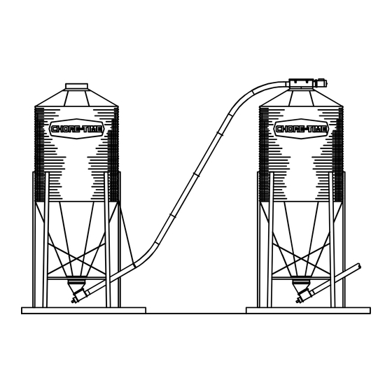
1038-5 6/01 108 Bin to Bin Fill Cap Kit The Model 108 Bin-to-Bin Fill Cap Kit is designed to accommodate filling or bypassing a hopper bin in a multiple bin application. Single or Twin Intermediate Fill Cap Kit... -
Page 5: Installation
3.Install the Tube Anchor Weldment (Item 5) on the inside of the Cover Weldment (Item 10). The long Tube Anchor Weldment (Item 11) is only required on Model 108 Single Bin Fill Cap Kits. 4.Set the Cover Weldment over the bin opening in line with the supply bin. -
Page 6: Twin Bin Fill Cap Kit (Model 108, 90, & 75)
Installation Bin Fill Cap Kit Twin Bin Fill Cap Kit (Model 108, 90, & 75) 1.Place the Sponge Tubing (Item 9) over the lip of the bin fill collar. 2.Bolt the two Tube Anchor Weldments (Item 5) to the same side of the Cover Weldment (Item 10). -
Page 7: Model 108 Bin To Bin Fill Cap Kit
Installation Model 108 Bin to Bin Fill Cap Kit The Model 108 Bin-to-Bin Fill Cap Kit is designed to accommodate filling or bypassing a hopper bin in a multiple bin application. Example: Units 1, 2, and 3 would be Bin-to-Bin Fill Cap Kits and unit 4 would be a Terminal Bin Fill Cap Kit. - Page 8 Installation Bin Fill Cap Kit The Extension Boot can be rotated in the desired direction when assembling with the Control Unit. Figure 3 shows each configuration along with the direction the feed flows inside the Bin-to-Bin Fill Cap Kit. STRETCH FLE X-AUG ER 8 IN C H ES P E R 50 FEET OF LE N G T H 1582-03 5/99 Item...
- Page 9 Bin Fill Cap Kit Installation 4.Assemble the Control Unit with long Tube Anchor Weldment (Item 1) in the upper inlet hole of the Cover Weldment (Item 3). 5.Use the hardware provide to bolt the Control Unit brackets to the support rails (Item 2). (See Figure 5.) Item Description Part No.
-
Page 10: Model 108 Single And Twin Intermediate Fill Cap Kit
Installation Bin Fill Cap Kit Model 108 Single and Twin Intermediate Fill Cap Kit 1.Place the Sponge Tubing (Item 12) over the lip of the bin fill collar. 2.Install the short Tube Anchor Weldment (Item 8) on the outside of the Bin Cover Weldment (Item 11). - Page 11 Bin Fill Cap Kit Installation 10.Assemble the Shut-Off using (6) 1/4-20 bolts and nuts provided into (3) center holes on each flanged side. This leaves the end holes for activator cord attachment. Item Description Part No. Fill Tube Weldment (Twin) 40522 Fill Tube Weldment (Single) 40523...
- Page 12 Installation Bin Fill Cap Kit 13. Attach red (closed side) and green (open side) indicator balls (Items 3 & 4) to the bottom ends of the cords. The cord should be routed over roof panels and side panels so as not to contact any sharp edges or hardware, and be able to be secured (tied off) to a leg or brace to hold slide in the open or closed position.
-
Page 13: Wiring
Bin Fill Cap Kit Wiring DANGER: Electrical Hazard Disconnect electrical power before inspecting or servicing equipment unless maintenance instructions specifically state otherwise. Ground all electrical equipment for safety. All electrical wiring must be done by a qualified electrician in accordance with local and national electric codes. -
Page 14: Parts Listing
Parts Listing Bin Fill Cap Kit Parts Listing Junction Box Assembly Part Number 46071 Item Description Part No. Gasket 42854 Control Decal 2529-261 Plastic Screw 42849 Electric Box Cover 42851 Mount Panel 46072 Machined Electrical Box 43883-1 Toggle Switch 7767 Box Mount Panel 46069 Shoulder Nut... -
Page 15: Power Unit Assembly Specifications
Bin Fill Cap Kit Parts Listing 50 Hz Fill System Power Units 1038-4 6/01 Item Description 3259-88 3259-104 3259-89 3259-105 3259-90 3259-106 Part No. Part No. Part No. Part No. Part No. Part No. Gearhead Assembly 3261-10 3261-10 3261-10 3261-10 3261-10 3261-10 5/16-18 x 5/8'' Hex Head Machine Screw 4412-1... - Page 16 5046 6104 3249 3249 Magnetic Pipe Plug 30160 30160 30160 30160 30160 30160 30160 3259-34 3259-39 3259-98 3259-88 3259-107 3259-108 3259-109 Item Description Part Number Motor 4229 5703 5977 6305 28035 26157 5977 90 deg. Connector 4228 4228 ---- ----...
-
Page 17: Models 75, 90, & 108 Single And Twin Bin Fill Cap Kit Parts List
Bin Fill Cap Kit Parts Listing Models 75, 90, & 108 Single and Twin Bin Fill Cap Kit Parts List Model 108 Model 90 Model 75 34635 25806 6563 Item Description Part No. Danger Electrical Decal 2527-25 2527-25 2527-25 Lid Ass’y... -
Page 18: Model 108 Bin-To-Bin Fill Cap Kit Parts List
Parts Listing Bin Fill Cap Kit Model 108 Bin-to-Bin Fill Cap Kit Parts List 1582-04 4/99 Item Description Part No. Item Description Part No. Support Rail 9851 24** Cover Weldment 6301 Gusset 9948 25** Back Plate Assembly 6298 Body Assembly... -
Page 19: Model 108 Single & Twin Intermediate Fill Cap Kit
Bin Fill Cap Kit Parts Listing Model 108 Single & Twin Intermediate Fill Cap Kit (40526) Twin Fill Kit (40527) Single Fill Kit 40526 40527 40526 40527 Item Description Part No. Item Description Part No. Danger Electrical Decal 2527-25 2527-25... - Page 20 Page No. Description of Change Various Combined MA1019 and MA1582 with this one. 35671 For additional parts and information, contact your nearest Chore-Time distributor or representative. Find your nearest distributor at: www.choretime.com/contacts CTB, Inc. PO Box 2000 Milford, Indiana 46542-2000 USA Phone (574) 658-4101 Email: choretime@choretime.com...
Need help?
Do you have a question about the 108 and is the answer not in the manual?
Questions and answers