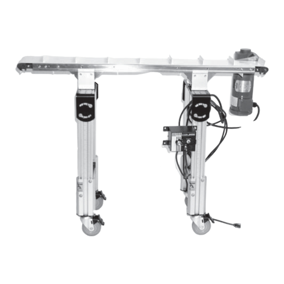
Dorner 6200 Series Installation, Maintenance & Parts Manual
Industrial end drive conveyors
Hide thumbs
Also See for 6200 Series:
- Installation, maintenance & parts manual (38 pages) ,
- Safety, setup, operation & maintenance manual (17 pages) ,
- Installation and maintenance manual (28 pages)
Table of Contents
Advertisement
Quick Links
. . . . . . . . . . . . . . . . . . . . . . . . . . . . . . . . . . . . .
. . . . . . . . . . . . . . . . . . . . . . . . . . . . . . .
. . . . . . . . . . . . . . . . . . . . . . . . . . . . . . . . . . . .
. . . . . . . . . . . . . . . . . . . . . . . . . . . . . . . . . . . . . .
. . . . . . . . . . . . . . . . . . . . . . . . . . . . . . . . .
. . . . . . . . . . . . . . . . . . . . . . . . . . . . .
. . . . . . . . . . . . . . . . . . . . . . . . . . . . . . . . .
2¨ to 6¨ (51 mm to 152 mm) Wide Conveyors
8¨ (203 mm) to 18¨ (457 mm) Wide
Flat Belt Conveyors
. . . . . . . . . . . . . . . . . . . . . . . . . .
Preventative Maintenance & Adjustment
. . . . . . . . . . . . . . . . . . . . . . . . . . . . . . . . .
. . . . . . . . . . . . . . . . . . . . . . . . . . . . . . .
. . . . . . . . . . . . . . . . . . . . . . . . . . . . . . . .
. . . . . . . . . . . . . . . . . . . . . . . . . . . . . . . . . . . . .
. . . . . . . . . . . . . . . . . . . . . . . . . . . . . . . . . . .
. . . . . . . . . . . . . . . . . . . . . . . . . . . . . . . .
. . . . . . . . . . . . . . . . . . . . . . . . . . . . . . .
. . . . . . . . . . . . . . . . . . . . . . . . . . . . . .
. . . . . . . . . . . . . . . . . . . . . . . . . . . . . . . . . . .
. . . . . . . . . . . . . . . . . . . . . . . . .
. . . . . . . . . . . . . . .
. . . . . . . . . . . . . . . . .
. . . . . . . . . . . .
. . . . . .
. . . . . . . . . . . . . .
. . . . . . . .
. . . . . . . . . . . . . . . . . . . . . . .
. . . . . . . . . . . . . . . . . . . . . .
. . . . . . . . . . . .
. . . . . . . . . . . .
. . . . . . . . . . . . .
. . . . . . . . . . . . . . . . . .
. . . . . . . . . . .
Installation, Maintenance
& Parts Manual
2
Belt Installation for Conveyor With Stands
2
and/or Gearmotor Mounting Package
3
3
4
. . . . . . . . . . . . . . . . . . . . . . . . . . . . . . .
4
4
0.47¨ (12 mm) Diameter Outboard Shaft
4
5
5
5
0.47¨ (12 mm) Diameter Output Shaft or Idler Pulley
6
Bearing Removal
7
8
8
8
Pulley Installation
8
. . . . . . . . . . . . . . . . . . . . . . . . . . . . . . . . . . .
8
8
8
8
9
9
9
9
9
9
9
Cleated Belt Return Roller
10
. . . . . . . . . . . . . . . . . . . . . . . . . . . . . . . . .
11
11
. . . . . . . . . . . . . . . . . . . . . . . . . . . . . . . . . . .
Table of Contents
. . . . . . . . . . . . .
. . . . . . . . . . . . . . . . . .
. . . . . . . . . . . . . . . . . . . . . . .
. . . . . . . . .
. . . . . . . . . . . . . . . . . . . . .
. . . . . . . . . . . . . . . .
. . . . . . . . . . . . . . . . . . . . . . . . . . . .
. . . . . . . . . . . . . . . . . . . . . . . . . .
. . . . . . .
. . . . . . . . . . . . . . . . . . . . . . . . . . . .
. . . . . . . . . . . . . . . . . . . . . . . . . .
. . . . . . . . . . . . . . . . . . . . . . . . . . . . .
. . . . . . . . . . . . . . . . . . . . . . . . .
. . . . . . . . . . . . . . . . . . . . . . . .
. . . . . . . . . . . . . . . . . .
. . . . . . . . . . . . . . . . . . .
. . . . . . .
. . . . . . . . . . . . . . . . . . . . . . .
. . . . . . . . .
. . . . . . . .
. . . . . . . . . . . . . .
. . . . . . . . . . . . .
. . . . . . . . . .
. . . . . . . . . .
. . . . . . . . . . . . . . . . . . . . . . .
. . . . . . . . . . . . . . . . . . . .
. . . . . . . . . . .
851-565 Rev. B
12
12
12
13
13
14
15
.
15
15
16
17
17
18
18
20
20
21
22
23
24
25
26
27
28
29
30
31
32
32
33
33
34
Advertisement
Table of Contents

Related Manuals for Dorner 6200 Series


Summary of Contents for Dorner 6200 Series
-
Page 1: Table Of Contents
Installation, Maintenance & Parts Manual 6200 Series Industrial End Drive Conveyors Table of Contents Warnings − General Safety ...... -
Page 2: 6200 Series Industrial End Drive Conveyors
D Inspect packages for shipping damage. Contact carrier regarding damage. D Accessories may be shipped loose. See accessory in- structions for installation. 6200 Series Industrial End Drive Conveyors Installation, Maintenance & Parts Manual 851-565 Rev. B Dorner Mfg. Corp. -
Page 3: Product Description
** For Heavy Load Bottom Mount Package, mount support under gear head. Figure 2 *** For conveyors longer than 13 ft (3962 mm), install support at joint. 6200 Series Industrial End Drive Conveyors Installation, Maintenance & Parts Manual Dorner Mfg. Corp. 851-565 Rev. B... -
Page 4: Installation
D Hex key wrenches: 4 mm, 5 mm return rollers. Refer to “Mounting Brackets” on page 5 D 10 mm open−end wrench and “Return Rollers” on page 6. 6200 Series Industrial End Drive Conveyors Installation, Maintenance & Parts Manual 851-565 Rev. B Dorner Mfg. Corp. -
Page 5: Conveyors Longer Than 13 Ft (3962 Mm)
(O) through frame and into connector bar (P) mounting bracket (V) with two screws (R). Do not on both sides. Tighten screws to 60 in-lb (7 Nm). tighten screws. 6200 Series Industrial End Drive Conveyors Installation, Maintenance & Parts Manual Dorner Mfg. Corp. 851-565 Rev. B... -
Page 6: Return Rollers
Loosely attach clip (AB or AD of Figure 13) on guard (AA) with two screws (AC). Do not tighten screws. Figure 13 Figure 11 6200 Series Industrial End Drive Conveyors Installation, Maintenance & Parts Manual 851-565 Rev. B Dorner Mfg. Corp. - Page 7 Return Roller Clip (2x) On 16−18 ft (4877−5486 mm) conveyor, repeat step 3 Low−Head Cap Screw M6−1.00 x 20mm (4x) for other return roller. 6200 Series Industrial End Drive Conveyors Installation, Maintenance & Parts Manual Dorner Mfg. Corp. 851-565 Rev. B...
-
Page 8: Required Tools
Disassemble support (AJ of Figure 18) and remove Grease bearing with one (1) pump from a manual hex shaft and shaft guard sections (AK). grease gun. Do not over-lubricate. 6200 Series Industrial End Drive Conveyors Installation, Maintenance & Parts Manual 851-565 Rev. B Dorner Mfg. Corp. -
Page 9: Return Rollers
Methyl Ethyl Ketone (MEK) or other harsh chemicals. If conveyor is equipped with guiding and accesso- ries or return rollers, remove them as necessary. 6200 Series Industrial End Drive Conveyors Installation, Maintenance & Parts Manual Dorner Mfg. Corp. 851-565 Rev. B... -
Page 10: Belt Removal For Conveyor With Stands And/Or Gearmotor Mounting Package
Remove two M6x12 mm socket head screws (AU). sure to provide support (AV of Figure 25) Remove bracket (AT). underneath the gearmotor while changing the belt. 6200 Series Industrial End Drive Conveyors Installation, Maintenance & Parts Manual 851-565 Rev. B Dorner Mfg. Corp. -
Page 11: Belt Removal For Conveyor With Optional Gang Drive Pulley
(AW of Figure 27). With a reversing gearmotor, a second bottom wiper must be installed on opposite on same side of conveyor. end. Remove conveyor belt (AR of Figure 26). 6200 Series Industrial End Drive Conveyors Installation, Maintenance & Parts Manual Dorner Mfg. Corp. 851-565 Rev. B... -
Page 12: Belt Installation For Conveyor With Optional Gang Drive Pulley
Slide belt (AR of Figure 23) onto conveyor frame label (AN of Figures 21 and 22), loosen four assembly. M6 low head screws (AO). 6200 Series Industrial End Drive Conveyors Installation, Maintenance & Parts Manual 851-565 Rev. B Dorner Mfg. Corp. -
Page 13: Pulley Removal
Belt Replacement” on page 9. Remove the desired pulley following instructions: − Drive Pulley with Standard 0.47¨ (12 mm) Diam- eter Output Shaft − Idler Pulley Figure 31 6200 Series Industrial End Drive Conveyors Installation, Maintenance & Parts Manual Dorner Mfg. Corp. 851-565 Rev. B... -
Page 14: B − Idler Pulley Removal
Figure 34 Remove two screws (AQ and AZ of Figure 35) and sleeves (BL) from conveyor (Y) and hex pinion (BM). Figure 37 6200 Series Industrial End Drive Conveyors Installation, Maintenance & Parts Manual 851-565 Rev. B Dorner Mfg. Corp. -
Page 15: C − Gang Drive Pulley Removal
Figure 41) over bearing (CD) with lip (CE) located in gap (CF) between bearing and spindle (CB) as shown. Figure 39 Repeat step 3 for opposite side. Figure 41 6200 Series Industrial End Drive Conveyors Installation, Maintenance & Parts Manual Dorner Mfg. Corp. 851-565 Rev. B... -
Page 16: Bearing Installation
Figure 47 Slide the sleeve of tool (part # 450282) (CK of Figure 45) over bearing. Repeat steps 1 through 5 for each bearing. 6200 Series Industrial End Drive Conveyors Installation, Maintenance & Parts Manual 851-565 Rev. B Dorner Mfg. Corp. -
Page 17: Bearing Replacement For A Gang Drive Pulley
(CP). While maintaining extension tool (CO) position, use a wrench to rotate bearing removal tool (CN) to expand flare. Figure 51 Figure 49 6200 Series Industrial End Drive Conveyors Installation, Maintenance & Parts Manual Dorner Mfg. Corp. 851-565 Rev. B... -
Page 18: Bearing Installation
Place and hold bearing (part # 21-33) (CR) onto tool (CT). Figure 56 Figure 54 Reverse the removal procedure “ ” (see page 13). 6200 Series Industrial End Drive Conveyors Installation, Maintenance & Parts Manual 851-565 Rev. B Dorner Mfg. Corp. - Page 19 Reverse the removal procedure “C” (see page 15). IMPORTANT: When installing clips (BV of Figure 57), ensure step (CU) is toward head plate (BW). Figure 57 6200 Series Industrial End Drive Conveyors Installation, Maintenance & Parts Manual Dorner Mfg. Corp. 851-565 Rev. B...
-
Page 20: Service Parts
Service Parts NOTE: For replacement parts other than those shown in this section, contact an authorized Dorner Service Center or the factory. Drive End Components Note: Items with an * are 13 Drive Tail Kit used on 10” (254mm), 12”... -
Page 21: Tension End Components
(51−76mm) Wide WW = Conveyor width ref.: 02, 03, 04, 05, 06, 08, 10, 12, 18 456015 Head Plate Tension LH 4−18” (102−457mm) Wide 6200 Series Industrial End Drive Conveyors Installation, Maintenance & Parts Manual Dorner Mfg. Corp. 851-565 Rev. B... -
Page 22: Conveyor Frame And Extensions
24’ (7316mm) 4720WW−13860 4741WW 11’ (3353mm) 4720WW−12660 12’ (3658mm) 4720WW−13860 WW = Conveyor width ref.: 02, 03, 04, 05, 06, 08, 10, 12, 18 6200 Series Industrial End Drive Conveyors Installation, Maintenance & Parts Manual 851-565 Rev. B Dorner Mfg. Corp. -
Page 23: Gang Drive Thru−Shaft Option
Thick Bottom Wiper 0.4970 Thick * 12” (305mm) 454712 454512 41−33 4528WWM Thin Bottom Wiper 0.4538 Thick ** 18” (457mm) 454718 454518 41−33 6200 Series Industrial End Drive Conveyors Installation, Maintenance & Parts Manual Dorner Mfg. Corp. 851-565 Rev. B... -
Page 24: −02 0.5" (13Mm) Bolt−On High Side Guides
460055−07200 Left Hand 460055−08400 Left Hand 460255−14139 460255−07460 7’ (2134mm) 7’ (2134mm) 18’ (5486mm) 18’ (5486mm) Right Hand 460055−08400 Right Hand 460155−14139 460155−07460 6200 Series Industrial End Drive Conveyors Installation, Maintenance & Parts Manual 851-565 Rev. B Dorner Mfg. Corp. -
Page 25: −03 Bolt−On Side Wipers
460155−07460 Left Hand 460055−07200 Left Hand 460255−14139 460255−07460 6’ (1829mm) 6’ (1829mm) 18’ (5486mm) 18’ (5486mm) Right Hand 460055−07200 Right Hand 460155−14139 460155−07460 6200 Series Industrial End Drive Conveyors Installation, Maintenance & Parts Manual Dorner Mfg. Corp. 851-565 Rev. B... -
Page 26: −04 3" (76 Mm) Bolt − On High Side Guides
460157−07460 Left Hand 460057−07200 Left Hand 460257−14139 460257−07460 6’ (1829mm) 6’ (1829mm) 18’ (5486mm) 18’ (5486mm) Right Hand 460057−07200 Right Hand 460157−14139 460157−07460 6200 Series Industrial End Drive Conveyors Installation, Maintenance & Parts Manual 851-565 Rev. B Dorner Mfg. Corp. -
Page 27: −05 1.5" (38Mm) Bolt−On High Side Guides
460156−07460 Left Hand 460056−07200 Left Hand 460256−14139 460256−07460 6’ (1829mm) 6’ (1829mm) 18’ (5486mm) 18’ (5486mm) Right Hand 460056−07200 Right Hand 460156−14139 460156−07460 6200 Series Industrial End Drive Conveyors Installation, Maintenance & Parts Manual Dorner Mfg. Corp. 851-565 Rev. B... -
Page 28: −13 Fully Adjustable Uhmw Guides
Guide Mounting Rail 10’ (3053mm) 202992 Guide Mounting Rail 11’ (3353mm) 920655M Socket Head Cap Screw M6−1.0 x 55mm 202993 Guide Mounting Rail 12’ (3658mm) 6200 Series Industrial End Drive Conveyors Installation, Maintenance & Parts Manual 851-565 Rev. B Dorner Mfg. Corp. -
Page 29: −20 Adjustable Width Uhmw Guides
Guide Mounting Rail 10’ (3048mm) 970620M Socket Head Set Screw M6−1.0 x 20mm 202992 Guide Mounting Rail 11’ (3353mm) 202993 Guide Mounting Rail 12’ (3658mm) 6200 Series Industrial End Drive Conveyors Installation, Maintenance & Parts Manual Dorner Mfg. Corp. 851-565 Rev. B... -
Page 30: 1" (25Mm) Cleated Belt Conveyor Guides
462145SSP 462166SSP 462155SSP Right Hand 462137SSP Right Hand 462146SSP 462166SSP 462156SSP 7’ 18’ (2134mm) (5486mm) Left Hand 462137SSP Left Hand 462156SSP 462166SSP 462146SSP 6200 Series Industrial End Drive Conveyors Installation, Maintenance & Parts Manual 851-565 Rev. B Dorner Mfg. Corp. -
Page 31: 2" (51Mm) Cleated Belt Conveyor Guides
462245SSP 462266SSP 462255SSP Right Hand 462237SSP Right Hand 462246SSP 462266SSP 462256SSP 7’ 18’ (2134mm) (5486mm) Left Hand 462237SSP Left Hand 462256SSP 462266SSP 462246SSP 6200 Series Industrial End Drive Conveyors Installation, Maintenance & Parts Manual Dorner Mfg. Corp. 851-565 Rev. B... -
Page 32: 2" (51 Mm) Through 6" (152 Mm) Flat Belt And
Return Roller Rod 920693M Low−Head Cap Screw M6−1.0 x 16mm WW = Conveyor width ref.: 08, 10, 12, 18 450599 Return Roller Clip Flat Belt 6200 Series Industrial End Drive Conveyors Installation, Maintenance & Parts Manual 851-565 Rev. B Dorner Mfg. Corp. -
Page 33: Conveyor Mounting Brackets
62−__ __ __ __ __ __ / __ __ V 6__ − __ __ __ __ __ __ __ __ __ __ __ V (Fill In) (Fill In) 6200 Series Industrial End Drive Conveyors Installation, Maintenance & Parts Manual Dorner Mfg. Corp. 851-565 Rev. B... -
Page 34: Return Policy
Authorization Number to reference. There will be a 15% restocking charge on all new items returned for credit where Dorner was not at fault. These will not be accepted after 60 days from original invoice date. The restocking charge covers inspection, cleaning, disassembly, and reissuing to inventory.
Need help?
Do you have a question about the 6200 Series and is the answer not in the manual?
Questions and answers