Dorner 6200 Series Installation, Maintenance & Parts Manual
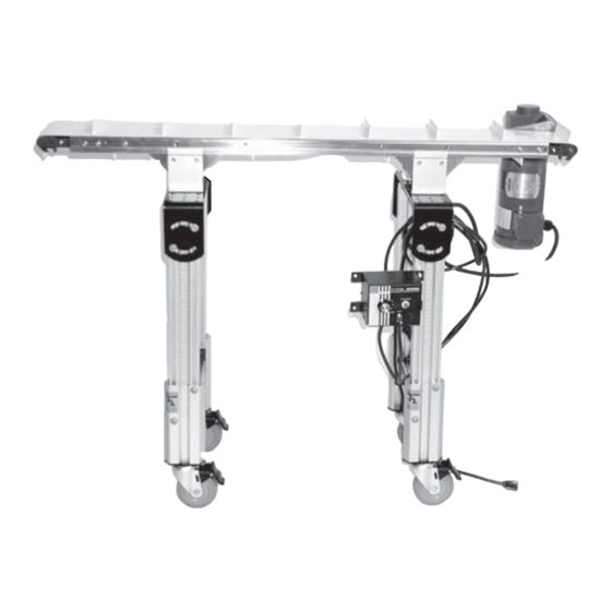
Industrial center drive conveyors
Hide thumbs
Also See for 6200 Series:
- Installation, maintenance & parts manual (38 pages) ,
- Safety, setup, operation & maintenance manual (17 pages) ,
- Installation and maintenance manual (28 pages)
Table of Contents
Advertisement
Quick Links
. . . . . . . . . . . . . . . . . . . . . . . . . . . . . . . . . . . . .
. . . . . . . . . . . . . . . . . . . . . . . . . . . . . . .
. . . . . . . . . . . . . . . . . . . . . . . . . . . . . . . . . . . .
. . . . . . . . . . . . . . . . . . . . . . . . . . . . . . . . . . . . . .
. . . . . . . . . . . . . . . . . . . . . . . . . . . . . . . . .
. . . . . . . . . . . . . . . . . . . . . . . . . . . . .
. . . . . . . . . . . . . . . . . . . . . . . . . . . . . . . . .
Preventative Maintenance & Adjustment
. . . . . . . . . . . . . . . . . . . . . . . . . . . . . . . . .
. . . . . . . . . . . . . . . . . . . . . . . . . . . . . . .
. . . . . . . . . . . . . . . . . . . . . . . . . . . . . . . .
. . . . . . . . . . . . . . . . . . . . . . . . . . . . . . . . . . . . .
. . . . . . . . . . . . . . . . . . . . . . . . . . . . . . . . . .
. . . . . . . . . . . . . . . . . . . . . . . . . . . . . . . . . .
. . . . . . . . . . . . . . . . . . . . . . . . . . . . . .
. . . . . . . . . . . . . . . . . . . . . . . . . . . . .
. . . . . . . . . . . . . . . . . . . . . . . . . . . . . . . . . .
. . . . . . . . . . . . . . . . . . . . . . . . . . . . . . .
. . . . . . . . . . . . . . . . . . . . . . . . .
. . . . . . . . . . . . . . .
. . . . . . . . . . . . . . . . .
. . . . . . . . . . . .
. . .
. . . . . . . . . . . . . .
. . . . . . . . . . . . . . . . . . . . . .
. . . . . . . . . . . . . . . . . . . . . .
. . . . . . . . . . .
. . . . . . . . . . . .
. . . . . . . . . . . . .
. . . . . . . . . . . . . . . . .
. . . . . . . . . .
. . . . . . . . . . . . . . . . . .
. . . . . . . . . . . . . . . . . . . . . . .
Installation, Maintenance
& Parts Manual
2
2
3
3
5
5
5
5
5
6
7
7
7
8
. . . . . . . . . . . . . . . . . . . . . . . . . . . . . . . . . . .
8
8
8
8
8
8
8
8
8
8
8
8
9
10
11
12
12
14
15
. . . . . . . . . . . . . . . . . . . . . . . . . . . . . . . . . . .
Table of Contents
. . . . . . . . . . . . . . .
. . . . . . . . . . . . . . . . .
. . . . . . . . . . . . . . . . . . . . .
. . . . . . . . . . . . . . . . . . . . .
. . . . . . . . . . . . . . . . . . . . . . . . .
. . . . . . . . . . . . . . . . . . . . . . . . . . . .
. . . . . . . . . . . . . . . . . . . . . . . . . .
. . . . . . . . . . . . .
. . . . . . . . . . . . . . . . . . . . . . . . . . . .
. . . . . . . . . . . . . . . . . . . . . . . . . .
. . . . . . . . . . . . .
. . . . . . . . . . . . . . . . . . . . . . . . . . . . .
. . . . . . . . . . . . . . . . . . . . . . . . .
. . . . . . . . . . . . . . . . . . . . . . . .
. . . . . . . . . . . . . . . . . .
. . . . . . . . . . . . . . . . . . .
. . . . . . . . . . . . . . . . . .
. . . . . . . .
. . . . . . . . . . . . . . . . . . . . . . . .
. . . . . . . . . .
. . . . . . . .
. . . . . . . . . . . . .
. . . . . . . . . . . . .
. . . . . . . . . . . . . . . . . . . . . . . . . . . .
. . . . . . . . . . . . . . . . . . . . . . . . . . . . .
. . . . . . . . . . . . . . . . . . . .
. . . . . . . . . . .
851-571 Rev. B
15
16
16
16
17
17
17
18
18
18
19
19
20
20
21
22
22
24
25
26
27
28
29
30
31
31
32
32
34
Advertisement
Table of Contents

Related Manuals for Dorner 6200 Series


Summary of Contents for Dorner 6200 Series
-
Page 1: Table Of Contents
Installation, Maintenance & Parts Manual 6200 Series Industrial Center Drive Conveyors Table of Contents Warnings − General Safety ...... -
Page 2: 6200 Series Industrial Center Drive Conveyors
D Inspect packages for shipping damage. Contact carrier regarding damage. D Accessories may be shipped loose. See accessory in- structions for installation. 6200 Series Industrial Center Drive Conveyors Installation, Maintenance & Parts Manual 851-571 Rev. B Dorner Mfg. Corp. -
Page 3: Product Description
I = 18¨ (457 mm) J = 6 ft (1829 mm)** ** For conveyors longer than 12 ft (3658 mm), install support at joint. 6200 Series Industrial Center Drive Conveyors Installation, Maintenance & Parts Manual Dorner Mfg. Corp. 851-571 Rev. B... - Page 4 Maximum conveyor loads are based on: Non-accumulating product Product moving towards gearmotor Conveyor being mounted horizontal Conveyor being located in a dry environment Conveyor with standard belt only 6200 Series Industrial Center Drive Conveyors Installation, Maintenance & Parts Manual 851-571 Rev. B Dorner Mfg. Corp.
-
Page 5: Installation
Figure 7 Connector Strips (2x) (Attached to conveyor section) Conveyor frame with belt Tension conveyor belt. Refer to “Conveyor Belt Tensioning” on page 14. 6200 Series Industrial Center Drive Conveyors Installation, Maintenance & Parts Manual Dorner Mfg. Corp. 851-571 Rev. B... -
Page 6: Mounting Brackets
(V). Snug−up screws (P). Figure 11 Repeat step 6 for other stand mounting bracket(s). Tighten all screws (P) to 80 in-lb (9 Nm). Figure 9 6200 Series Industrial Center Drive Conveyors Installation, Maintenance & Parts Manual 851-571 Rev. B Dorner Mfg. Corp. -
Page 7: Return Rollers
(V). Tighten screws (AD of Figure 16) to 80 in-lb (9 Nm). Figure 17 On 16−18 ft (4877−5486 mm) conveyor, repeat step 3 Figure 14 for other return roller. 6200 Series Industrial Center Drive Conveyors Installation, Maintenance & Parts Manual Dorner Mfg. Corp. 851-571 Rev. B... -
Page 8: Required Tools
D Install New Conveyor Belt D Worn knurl or impacted dirt on drive pulley D Intermittent jamming or drive train problems D Tension Conveyor Belt 6200 Series Industrial Center Drive Conveyors Installation, Maintenance & Parts Manual 851-571 Rev. B Dorner Mfg. Corp. -
Page 9: Belt Removal For Conveyor Without Gearmotor Mounting Package Or Stands
Remove conveyor belt (AR of Figure 23) from both ends of conveyor. Figure 23 Proceed to “Center Drive Module Removal” on page Figure 20 6200 Series Industrial Center Drive Conveyors Installation, Maintenance & Parts Manual Dorner Mfg. Corp. 851-571 Rev. B... -
Page 10: Belt Removal For Conveyor With Stands And/Or Gearmotor Mounting Package
(AJ). Using finger grip holes (AL of Figure 20), open tension Figure 25 door (AM) to release conveyor belt tension. 6200 Series Industrial Center Drive Conveyors Installation, Maintenance & Parts Manual 851-571 Rev. B Dorner Mfg. Corp. -
Page 11: Center Drive Module Removal
Figure 30 Remove conveyor belt (AR of Figure 29) from conveyor end. Remove module. 6200 Series Industrial Center Drive Conveyors Installation, Maintenance & Parts Manual Dorner Mfg. Corp. 851-571 Rev. B... -
Page 12: Belt Removal From Center Drive Module
Belt travel direction is identified by an arrow decal on the side of the conveyor (BJ of Figures 34 & 35). Figure 34 Figure 32 6200 Series Industrial Center Drive Conveyors Installation, Maintenance & Parts Manual 851-571 Rev. B Dorner Mfg. Corp. - Page 13 (AN of Figures 21 and 22), loosen four Figure 33) into belt loop and replace in center drive M6 low head screws (AO). 6200 Series Industrial Center Drive Conveyors Installation, Maintenance & Parts Manual Dorner Mfg. Corp. 851-571 Rev. B...
-
Page 14: Conveyor Belt Tensioning
(BP of Figure 41), the conveyor belt must be replaced Figure 41 Conveyor is equipped with automatic tensioning cylin- der. No tensioning adjustment is required. Figure 39 6200 Series Industrial Center Drive Conveyors Installation, Maintenance & Parts Manual 851-571 Rev. B Dorner Mfg. Corp. -
Page 15: Pulley Removal
Remove screw (AQ of Figure 43) and sleeve (BR) Locate magnet (BV of Figure 45) on spindle and from conveyor (V) and hex pinion (BQ). bearing assembly (BW). 6200 Series Industrial Center Drive Conveyors Installation, Maintenance & Parts Manual Dorner Mfg. Corp. 851-571 Rev. B... -
Page 16: Fixed End Pulley Removal
D For 5¨ (127 mm) or wider conveyor, depress both spindle and bearing assembly. sides of each spring-loaded shaft (CJ of Figure 49). Remove pulleys (CK). Figure 47 Figure 49 6200 Series Industrial Center Drive Conveyors Installation, Maintenance & Parts Manual 851-571 Rev. B Dorner Mfg. Corp. -
Page 17: Bearing Replacement For Tension End And Fixed End Pulleys
Place open end of shaft (CU of Figure 55) into Using a puller (CR of Figure 52), remove and sleeve. discard bearing(s). Figure 55 Figure 52 6200 Series Industrial Center Drive Conveyors Installation, Maintenance & Parts Manual Dorner Mfg. Corp. 851-571 Rev. B... -
Page 18: Bearing Replacement For Drive Pulley
Using an arbor press or similar device, press bearing (CW) onto pulley shaft as shown. Figure 57 Repeat steps 1 through 4 for other bearing. 6200 Series Industrial Center Drive Conveyors Installation, Maintenance & Parts Manual 851-571 Rev. B Dorner Mfg. Corp. -
Page 19: Bearing Replacement For Idler Pulleys
Reverse the removal procedure “ ” (see page 16). D − Idler Pulley Reverse the removal procedure “ ” (see page 16). Figure 60 6200 Series Industrial Center Drive Conveyors Installation, Maintenance & Parts Manual Dorner Mfg. Corp. 851-571 Rev. B... -
Page 20: Service Parts
Service Parts Service Parts NOTE: For replacement parts other than those shown in this section, contact an authorized Dorner Service Center or the factory. Fixed End Components 15 Fixed End Tail Kit 16 Fixed End Spindle Kit Item Part Number... -
Page 21: Tension End Components
(51−76mm) Wide WW = Conveyor width ref.: 02, 03, 04, 05, 06, 08, 10, 12, 18 456015 Head Plate Tension LH 4−18” (102−457mm) Wide 6200 Series Industrial Center Drive Conveyors Installation, Maintenance & Parts Manual Dorner Mfg. Corp. 851-571 Rev. B... -
Page 22: Center Drive Module 5" (127Mm) Through 18" (457Mm) Wide Conveyors
Center Drive Module − 5” (127mm) Through 18” (457mm) Wide Conveyors 34 Center Drive Kit Center Drive Module − 2” (51mm) Through 4” (102mm) Wide Conveyors 33 Center Drive Kit 6200 Series Industrial Center Drive Conveyors Installation, Maintenance & Parts Manual 851-571 Rev. B Dorner Mfg. Corp. - Page 23 Pulley Sub Assy Flat 4” (102mm) WW = Conveyor width ref.: 02, 03, 04, 05, 06, 08, 10, 12, 18 463402 Shaft Hex 2” (51mm) 6200 Series Industrial Center Drive Conveyors Installation, Maintenance & Parts Manual Dorner Mfg. Corp. 851-571 Rev. B...
-
Page 24: Conveyor Frame And Extension
24’ (7316mm) 4720WW−13860 4741WW 11’ (3353mm) 4720WW−12660 12’ (3658mm) 4720WW−13860 WW = Conveyor width ref.: 02, 03, 04, 05, 06, 08, 10, 12, 18 6200 Series Industrial Center Drive Conveyors Installation, Maintenance & Parts Manual 851-571 Rev. B Dorner Mfg. Corp. -
Page 25: 02 0.5" (13Mm) Bolt On High Side Guides
460055−10800 Left Hand 460055−12000 Left Hand 460255−14139 460255−14660 10’ (3048mm) 10’ (3048mm) 24’ (7315mm) 24’ (7315mm) Right Hand 460055−12000 Right Hand 460155−14139 460155−14660 6200 Series Industrial Center Drive Conveyors Installation, Maintenance & Parts Manual Dorner Mfg. Corp. 851-571 Rev. B... -
Page 26: Bolt On Side Wipers
460155−14660 Left Hand 460055−10800 Left Hand 460255−14139 460255−14660 9’ (2743mm) 9’ (2743mm) 24’ (7315mm) 24’ (7315mm) Right Hand 460055−10800 Right Hand 460155−14139 460155−14660 6200 Series Industrial Center Drive Conveyors Installation, Maintenance & Parts Manual 851-571 Rev. B Dorner Mfg. Corp. -
Page 27: 04 3" (76Mm) Bolt On High Side Guides
460157−14660 Left Hand 460057−10800 Left Hand 460257−14139 460257−14660 9’ (2743mm) 9’ (2743mm) 24’ (7315mm) 24’ (7315mm) Right Hand 460057−10800 Right Hand 460157−14139 460157−14660 6200 Series Industrial Center Drive Conveyors Installation, Maintenance & Parts Manual Dorner Mfg. Corp. 851-571 Rev. B... -
Page 28: 05 1.5" (38Mm) Bolt On High Side Guides
460056−09600 Left Hand 460256−14139 460256−14660 Left Hand 460056−10800 24’ (7315mm) 24’ (7315mm) 9’ (2743mm) 9’ (2743mm) Right Hand 460156−14139 460156−14660 Right Hand 460056−10800 6200 Series Industrial Center Drive Conveyors Installation, Maintenance & Parts Manual 851-571 Rev. B Dorner Mfg. Corp. -
Page 29: Fully Adjustable Uhmw Guides
55mm 202993 Guide Mounting Rail 12’ (3658mm) 461300M Support Assembly, Adjustable Guide (Includes Items: 3 through 12) 202994 Guide Mounting Rail 13’ (3962mm) 6200 Series Industrial Center Drive Conveyors Installation, Maintenance & Parts Manual Dorner Mfg. Corp. 851-571 Rev. B... -
Page 30: Adjustable Width Uhmw Guides
12mm 202993 Guide Mounting Rail 12’ (3658mm) 462300M Support Assembly, Gull Wing (Includes Items: 3 through 9) 202994 Guide Mounting Rail 13’ (3962mm) 6200 Series Industrial Center Drive Conveyors Installation, Maintenance & Parts Manual 851-571 Rev. B Dorner Mfg. Corp. -
Page 31: 2" (51Mm) Through 6" (152Mm) Wide Flat Belt Return Roller
Return Roller Rod 920693M Low−Head Cap Screw M6−1.0 x 16mm WW = Conveyor width ref.: 08, 10, 12, 18 450599 Return Roller Clip Flat Belt 6200 Series Industrial Center Drive Conveyors Installation, Maintenance & Parts Manual Dorner Mfg. Corp. 851-571 Rev. B... -
Page 32: Conveyor Mounting Brackets
01 and belt type /02 (general purpose) 65−__ __ __ __ __ __ / __ __ V 65−030200/02V Belt (Fill In) 6200 Series Industrial Center Drive Conveyors Installation, Maintenance & Parts Manual 851-571 Rev. B Dorner Mfg. Corp. - Page 33 Notes 6200 Series Industrial Center Drive Conveyors Installation, Maintenance & Parts Manual Dorner Mfg. Corp. 851-571 Rev. B...
-
Page 34: Return Policy
Authorization Number to reference. There will be a 15% restocking charge on all new items returned for credit where Dorner was not at fault. These will not be accepted after 60 days from original invoice date. The restocking charge covers inspection, cleaning, disassembly, and reissuing to inventory.
Need help?
Do you have a question about the 6200 Series and is the answer not in the manual?
Questions and answers