Table of Contents
Advertisement
Quick Links
UM0600
User manual
STM3210C-EVAL
evaluation board
Introduction
The STM32F107VCT evaluation board STM3210C-EVAL is designed as a complete
development platform for STMicroelectronic's ARM Cortex-M3 core-based STM32F107VCT
microcontroller with full speed USB-OTG, ethernet MAC, two channels of CAN2.0A/B
compliant interface, 2 channels I2S, 2 channels I2C, 5 channels USART with smartcard
support, 3 channels SPI, internal 64 KB SRAM and 256 KB Flash, JTAG and SWD
debugging support.
The full range of hardware features on the board help you evaluate all peripherals (USB-
TM
OTG FS, ethernet, motor control, CAN, microSD card
, smartcard, USART, audio DAC,
MEMS, EEPROM... etc.) and develop your own applications. Extension headers make it
easy to connect a daughterboard or wrapping board for your specific application.
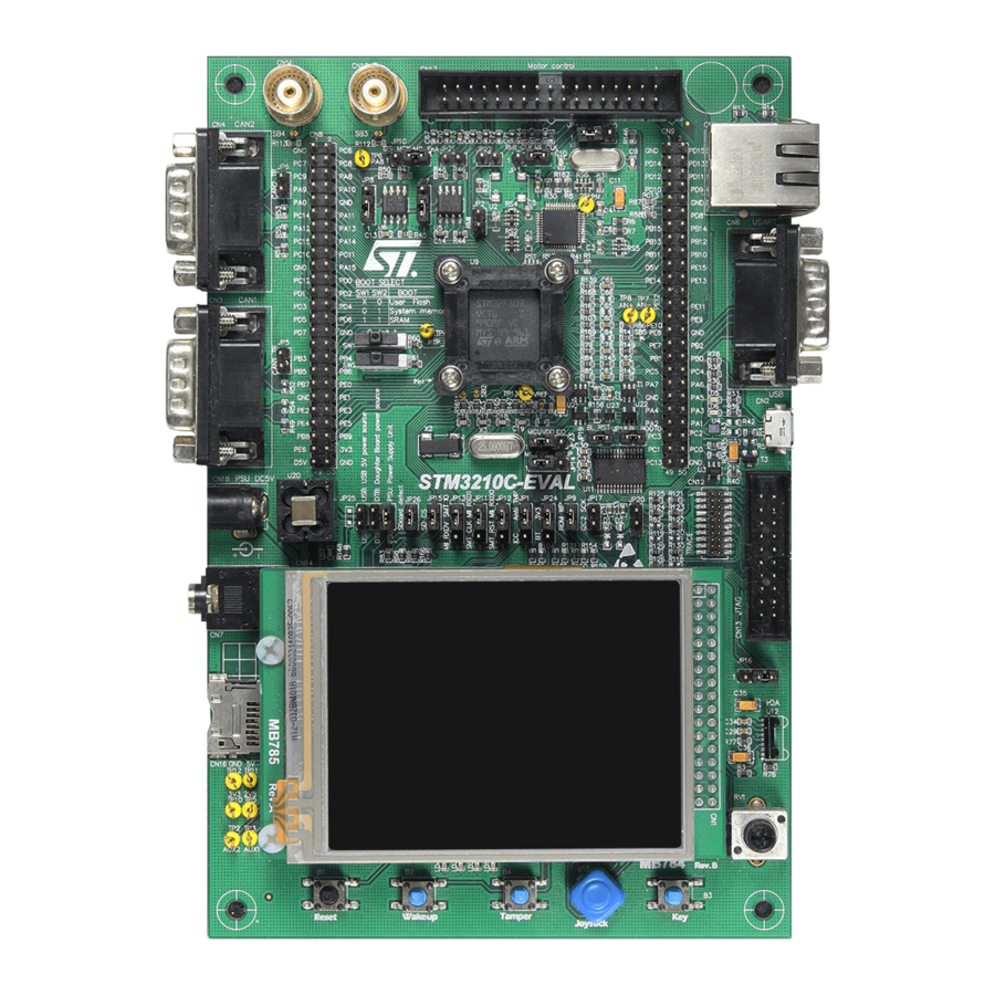
Figure 1.
STM3210C-EVAL evaluation board
October 2009
Doc ID 15082 Rev 3
1/52
www.st.com
Downloaded from
Elcodis.com
electronic components distributor
Advertisement
Chapters
Table of Contents

Related Manuals for ST STM3210C-EVAL


Summary of Contents for ST STM3210C-EVAL
- Page 1 STM3210C-EVAL evaluation board Introduction The STM32F107VCT evaluation board STM3210C-EVAL is designed as a complete development platform for STMicroelectronic's ARM Cortex-M3 core-based STM32F107VCT microcontroller with full speed USB-OTG, ethernet MAC, two channels of CAN2.0A/B compliant interface, 2 channels I2S, 2 channels I2C, 5 channels USART with smartcard support, 3 channels SPI, internal 64 KB SRAM and 256 KB Flash, JTAG and SWD debugging support.
-
Page 2: Table Of Contents
Contents UM0600 Contents Overview ..........4 Features . - Page 3 Schematics ..........30 Appendix A STM3210C-EVAL I/O assignment ......48 Revision history .
-
Page 4: Overview
Demonstration software is preloaded in the board’s Flash memory for easy demonstration of device peripherals in stand-alone mode. For more information and to download the latest version available, please refer to STM3210C-EVAL demonstration firmware available on the web: www.st.com/mcu. Order code To order the STM32F107VCT evaluation board, use the order code STM3210C-EVAL. -
Page 5: Hardware Layout And Configuration
UM0600 Hardware layout and configuration Hardware layout and configuration The STM3210C-EVAL evaluation board is designed around the STM32F107VCT in a 100- pin LQFP package. The hardware block diagram Figure 2 illustrates the connection between the STM32F107VCT and peripherals (LCD, EEPROM, MEMS, USART, IrDA, USB-OTG,... - Page 6 Hardware layout and configuration UM0600 Figure 3. STM3210C-EVAL evaluation board layout CN8, CN9 Extension header CN17 Motor control CN10, CN11 BNC RJ45 CAN2 connector RS-232 STM32F107VCT CAN1 USB MicroAB connector CN12 CN18 Trace 5V power CN13 JTAG Audio jack CN14...
-
Page 7: Power Supply
Hardware layout and configuration Power supply The STM3210C-EVAL evaluation board is designed to be powered by a 5 V DC power supply and to be protected by PolyZen from a wrong power plug-in event. It is possible to configure the evaluation board to use any of following three sources for the power supply. - Page 8 1 Kohm) in series and IDD current measurement circuit in parallel when JP23 is set as shown to the right. MCU power consumption measurement is enabled. The LED LD7 is lit when the STM3210C-EVAL board is powered by the 5 V correctly. 8/52 Doc ID 15082 Rev 3 Downloaded from Elcodis.com...
-
Page 9: Boot Option
RC clock is used. Reset source The reset signal of the STM3210C-EVAL board is active low and the reset sources include: Reset button, B1 Debugging tools from JTAG connector CN13 and trace connector CN12 Daughterboard from CN9 RS-232 connector CN6 for ISP when JP19 is fitted. -
Page 10: Audio
UM0600 Audio The STM3210C-EVAL evaluation board supports stereo audio play by using an audio DAC CS43L22 connected to both an I2S2 port and one channel of the DAC of microcontroller STM32F107VCT. The CS43L22 can be configured via the I2C1 bus when JP9 is fitted (default setting). -
Page 11: Rs-232 And Irda
Both RS-232 and IrDA communications are supported by D-type 9-pin RS-232 connectors CN6 and IrDA transceiver U12 which connect to USART2 of the STM32F107VCT on the STM3210C-EVAL evaluation board. Two signals, Bootloader_BOOT0 and Bootloader_RESET, are added on the RS-232 connector for ISP support. -
Page 12: Motor Control
Hardware layout and configuration UM0600 Motor control The STM3210C-EVAL evaluation board supports a three-phase brushless motor control via a 34-pin connector CN17, which provides all required control and feedback signals to and from a motor power-driving board. Available signals on this connector include emergency stop, motor speed, 3 phase motor current, bus voltage, heat sink temperature from the motor driving board and 6 channels of PWM control signal going to the motor driving circuit. -
Page 13: Smartcard
Hardware layout and configuration 2.10 Smartcard STMicroelectronic’s smartcard interface chip ST8024 is used on the STM3210C-EVAL board for asynchronous 3 V and 5 V smartcards. It performs all supply protection and control functions based on the connections with the STM32F107VCT listed in Table Table 10. -
Page 14: Microsd Card
Hardware layout and configuration UM0600 2.11 MicroSD card The 2 GByte (or more) microSD card connected to SPI3 of STM32F107VCT is available on the board. MicroSD card detection is managed by the standard I/O port PE0. JP15 must remain fitted to enable microSD card chip select. Table 12. -
Page 15: Ethernet
The evaluation board can be powered by this USB connection at 5 V DC with a 500 mA current limitation. LED LD6 is lit: in Host mode when the power switch (U3) is ON (STM3210C-EVAL is acting as a USB host), in Device mode when a cable is connected to a PC (STM3210C-EVAL is acting as a USB device and VBUS is powered by another USB host). -
Page 16: Mems
Hardware layout and configuration UM0600 2.15 MEMS An ST MEMS device LIS302DL is connected to the I2C1 bus of STM32F107VCT. 2.16 Development and debug support The two debug connectors available on STM3210C-EVAL evaluation board are: CN13, standard 20-pin JTAG interface connector that is compliant with the debug tools of ARM7 and ARM9 and cortex M3. -
Page 17: Display And Input Devices
MII_CRS of the ethernet. You may refer to Table 2 for details. The STM3210C-EVAL board also supports a second optional 2.4” TFT LCD without touch screen that can be mounted on CN15 connector. The 2.4” TFT LCD is not populated by default. -
Page 18: Idd Measurement
Figure 4. STM3210C-EVAL IDD measurement circuit The circuit above is implemented on STM3210C-EVAL for IDD measurement. In Run mode, IDD current is measured using MAX9938FEUK+ (U21) connected to the 1ohm shunt resistor. In this case IDD_CNT_EN remains high during measurement and JP23 jumper must be set to 2<->3. - Page 19 UM0600 Hardware layout and configuration Figure 5. STM3210C-EVAL IDD Low power mode measurement timing diagram IDD measure Stop or Standby Wake-up Clear CNT MCU mode 150ms 300ms 450ms IDD_CNT_EN Q13=LOW_POWER_EN (T2 pin 3) Q14=LP_WAKEUP Q14n=Switch control (U22 pin 4) The Low power mode measurement procedure can be used in Stop or Standby modes if the IDD current does not exceed 60 uA, otherwise the Run mode measurement procedure should be used up to 60 mA.
-
Page 20: Connectors
Connectors UM0600 Connectors Motor control connector CN17 Figure 6. Motor control connector CN17 viewed from above the PCB Table 15. Motor control connector CN17 Pin of Pin number Pin number Pin of Description Description STM32F107VCT of CN17 of CN17 STM32F107VCT Emergency stop PE15 PWM-UH... -
Page 21: Analog Input Connector Cn10 And Cn11
UM0600 Connectors Analog input connector CN10 and CN11 Figure 7. Analog input connector CN10 and CN11 viewed from the bottom Table 16. Analog input connector CN10 and CN11 Pin number Description Pin number Description Analog input PB0 and PA7 for CN10 and CN11 respectively CAN D-type 9-pin male connector CN3 and CN4 Figure 8. -
Page 22: Ethernet Rj45 Connector Cn1
Connectors UM0600 Ethernet RJ45 connector CN1 Figure 9. Ethernet RJ45 connector CN1 viewed from the front Table 18. RJ45 connector CN1 Pin number Description Pin number Description TxData+ TxData- RxData+ Shield Shield RxData- Shield Shield Trace debugging connector CN12 Figure 10. Trace debugging connector CN12 viewed from above the PCB 19 17 15 13 11 9 7 5 3 18 16 14 12 10 8 6 4... -
Page 23: Rs-232 Connector Cn6
UM0600 Connectors RS-232 connector CN6 Figure 11. RS-232 connector CN6 with ISP support viewed from the front Table 20. RS-232 connector CN6 with ISP support Pin number Description Pin number Description Bootloader_RESET RS232_RX (PD6) RS232_TX (PD5) Bootloader_BOOT0 JTAG debugging connector CN13 Figure 12. -
Page 24: Daughterboard Extension Connector Cn8 And Cn9
Daughterboard extension connector CN8 and CN9 Two 50-pin male headers CN8 and CN9 can be used to connect a daughterboard or standard wrapping board to the STM3210C-EVAL evaluation board. All 80 GPI/Os are available on it. The space between these two connectors and power position, GND and RESET pin are defined as a standard, which allows to develop common daughterboards for several evaluation boards. - Page 25 UM0600 Connectors Table 22. Daughterboard extension connector CN8 (continued) Description Alternative function How to disconnect with function block on STM3210C-EVAL Trace_D3 I2S_MCK/MC JP10 open Disconnect STM3210C-EVAL board from motor power drive board JP4 open PA10 USB_ID Remove R38 or disconnect USB cable...
- Page 26 Connectors UM0600 Table 23. daughterboard extension connector CN9 Description Alternative function How to disconnect with component on STM3210C-EVAL board Keep JP22 open. Disconnect STM3210C-EVAL board from motor PD14 power drive board. PD12 Ethernet Remove RS2 PD10 Ethernet/Smartcard Keep JP11 open...
-
Page 27: Audio Jack Cn7
UM0600 Connectors Table 23. daughterboard extension connector CN9 (continued) Description Alternative function How to disconnect with component on STM3210C-EVAL board PB12 Ethernet / Audio Remove RS3 PB10 Ethernet Remove RS2 PE15 Remove R139 PE13 Disconnect STM3210C-EVAL board from motor power drive board... -
Page 28: Microsd Card Connector Cn16
Connectors UM0600 3.11 MicroSD card connector CN16 Figure 13. MicroSD card connector CN16 viewed from the front Table 24. MicroSD card connector CN16 Pin number Description Pin number Description Vss/GND MicroSDcard_CS (PA4) MicroSDcard_DOUT(PC11) MicroSDcard_DIN(PC12) +3V3 MicroSDcard_CLK (PC10) MicroSDcard_detect (PE0) 3.12 USB MicroAB connector CN2 Figure 14. -
Page 29: Power Connector Cn18
UM0600 Connectors 3.13 Power connector CN18 Your STM3210C-EVAL evaluation board can be powered from a DC 5 V power supply via the external power supply jack (CN18) shown in Figure 15. The central pin of CN18 must be positive. Figure 15. Power supply connector CN18 viewed from the front DC +5V 3.14... -
Page 30: Schematics
Schematics UM0600 Schematics This section provides the following schematics: Figure 17: STM3210C on page 31 Figure 18: MCU on page 32 Figure 19: Ethernet on page 33 Figure 20: Full speed USB-OTG on page 34 Figure 21: Audio on page 35 Figure 22: LCD on page 36 Figure 23: I/O expander on page 37 Figure 24: CAN on page 38... -
Page 31: Figure 17: Stm3210C
Note1: only decoupling capacitors value was updated from Versioin B.1 to B.2. Bootloader_RESET Bootloader_RESET Note2: only assembly request of R42 and R43 was updated from Versioin B.2 to B.3. Bootloader_BOOT0 Bootloader_BOOT0 STMicroelectronics Title: STM3210C-EVAL Number: MB784 Rev: B.3(PCB.SCH) Date: 9/18/2009 Sheet Downloaded from Elcodis.com... -
Page 32: Figure 18: Mcu
JP18 JP19: open/ BL_Reset disabled close / BL_Reset MC_PFCsync2 09.03290.01 STM32F107VCT JP26 RESET +3V3 +3V3 MicroSDCard_Detection STMicroelectronics [N/A] 100nF Bootloader_BOOT0 Title: STM3210C-EVAL MCU JP19 RESET# Bootloader_RESET 1N4148 Number: MB784 Rev: B.3(PCB.SCH) Date: 10/10/2009 Sheet Downloaded from Elcodis.com electronic components distributor... -
Page 33: Figure 19: Ethernet
External 25MHz crystal mode +3V3 ===================== JP4 1<->2 (MCO pin free for another 10uF 100nF 100nF 100nF 100nF 100nF 100nF application) SM7745HEV-50.0M (do not fit) STMicroelectronics Title: STM3210C-EVAL Ethernet Number: MB784 Rev: B.3(PCB.SCH) Date: 9/18/2009 Sheet Downloaded from Elcodis.com electronic components distributor... -
Page 34: Figure 20: Full Speed Usb-Otg
VBUS USB_PowerSwitchOn TPS2041BDBV 4.7uF Shield 475900001 +3V3 USB_VBUS PA11 USB_DM PA12 USB_DP PA10 USB_ID Green Vbus D+out D+in D-out D-in 9013 EMIF02-USB03F2 [N/A] STMicroelectronics Title: STM3210C-EVAL USB_OTG_FS Number: MB784 Rev: B.3(PCB.SCH) Date: 9/18/2009 Sheet Downloaded from Elcodis.com electronic components distributor... -
Page 35: Figure 21: Audio
AIN3A AIN4B AIN4A 100nF 100nF 100nF TSTO +3V3 TSTO AFILTB AFILTA DGND FILT+ GND/Thermal Pad AGND 100nF CS43L22 I2C address 0x94 150pF(COG) 150pF(COG) STMicroelectronics Title: STM3210C-EVAL Audio Number: MB784 Rev: B.3(PCB.SCH) Date: 9/18/2009 Sheet Downloaded from Elcodis.com electronic components distributor... -
Page 36: Figure 22: Lcd
TouchScreen_X- TouchScreen_X+ TouchScreen_Y- TouchScreen_Y+ 3.2" LCD_connector (MB785 with AM-240320D4TOQW-T00H(R)) CN15 RESET +3V3 +3V3 BL_VDD BL_Control BL_GND BL_GND 2.4" LCD connector (MB542 with AM240320L8TNQW-00H) STMicroelectronics Title: STM3210C-EVAL LCD Number: MB784 Rev: B.3(PCB.SCH) Date: 9/18/2009 Sheet Downloaded from Elcodis.com electronic components distributor... -
Page 37: Figure 23: I/O Expander
EXP_IO1 EXP_IO2 EXP_IO3 SCLK EXP_IO4 SDAT EXP_IO5 EXP_IO6 Data in EXP_IO7 R160 A0/Data Out EXP_IO8 R164 STMPE811 I2C device address:0x88 +3V3 100K +3V3 STMicroelectronics Title: STM3210C-EVAL IO_Expandor Number: MB784 Rev: B.3(PCB.SCH) Date: 9/18/2009 Sheet Downloaded from Elcodis.com electronic components distributor... -
Page 38: Figure 24: Can
SN65HVD230 [N/A] +3V3 +3V3 +3V3 Default setting: 1<->2 DB9-male CAN connector Default setting: Open 100nF CAN2_TX CANH CANL CAN2_RX Vref SN65HVD230 [N/A] +3V3 STMicroelectronics Title: STM3210C-EVAL CAN Number: MB784 Rev: B.3(PCB.SCH) Date: 9/18/2009 Sheet Downloaded from Elcodis.com electronic components distributor... -
Page 39: Figure 25: Rs-232 And Irda
R3IN RS232/IrDA_RX Bootloader_BOOT0 R4OUT R4IN R5OUT R5IN +3V3 JP16 nSHDN ST3241EBPR +3V3 Anode (VCC2) Cathode VCC1 Vlogic TFDU4300 4.7uF 4.7uF 100nF 100nF STMicroelectronics IrDA Title: STM3210C-EVAL RS232&IrDA Number: MB784 Rev: B.3(PCB.SCH) Date: 9/18/2009 Sheet Downloaded from Elcodis.com electronic components distributor... -
Page 40: Figure 26: Smartcard
10uF 100nF PRES RSTIN R166 PRES CMDVCC 10uF 100nF PORADJ AUX2 AUX1 +3V3 CGND ST8024CDR SmartCard_RST PE14 SmartCard_CMDVCC 100nF C816 +3V3 100K STMicroelectronics Title: STM3210C-EVAL Smart card Number: MB784 Rev: B.3(PCB.SCH) Date: 9/18/2009 Sheet Downloaded from Elcodis.com electronic components distributor... -
Page 41: Figure 27: Motor Control
R144 0 Default setting: Open BNC2 BNC1 [N/A] [N/A] JP21 [N/A] MC_PFCsync2 JP22 PD14 Default setting: Open MC_PFCsync1 [N/A] 10nF [N/A] [N/A] [N/A] STMicroelectronics Title: STM3210C-EVAL Motor control Number: MB784 Rev: B.3(PCB.SCH) Date: 9/18/2009 Sheet Downloaded from Elcodis.com electronic components distributor... -
Page 42: Figure 28: I/O Peripherals
R115 Potentiometer R104 PC13 R105 User_Button Anti_Tamper WKUP 10nF [N/A] Potentiometer USER Tamper R116 100nF 100nF WAKEUP STMicroelectronics R117 R110 R111 220K Title: STM3210C-EVAL IO Peripherals BUTTON Number: MB784 Rev: B.3(PCB.SCH) Date: 9/18/2009 Sheet Downloaded from Elcodis.com electronic components distributor... -
Page 43: Figure 29: Extension Connector
47 48 PC13 49 50 49 50 Header 25X2 Header 25X2 PA[0..15] PA[0..15] PB[0..15] PB[0..15] PC[0..15] PC[0..15] PD[0..15] PD[0..15] PE[0..15] PE[0..15] RESET# RESET# STMicroelectronics Title: STM3210C-EVAL Extension connector Number: MB784 Rev: B.3(PCB.SCH) Date: 9/18/2009 Sheet Downloaded from Elcodis.com electronic components distributor... -
Page 44: Figure 30: Jtag And Trace
[N/A] R129 0 R126 R119 [N/A] R130 0 R120 [N/A] R127 R128 JTAG connector TRACE_D3 TRACE_D2 TRACE_D1 TRACE_D0 TRACE_CK Trace connector STMicroelectronics Title: STM3210C-EVAL JTAG & Trace Number: MB784 Rev: B.3(PCB.SCH) Date: 9/18/2009 Sheet Downloaded from Elcodis.com electronic components distributor... - Page 45 Figure 31. MicroSD card +3V3 R138 PC11 R135 MicroSDCard_MISO PC10 MicroSDCard_SCK +3V3 PC12 MicroSDCard_MOSI R136 MicroSDCard_CS CN16 PJS008-2000 SMS064FF or SMS128FF R137 MicroSDCard_Detection MicroSD card STMicroelectronics Title: STM3210C-EVAL MicroSD card Number: MB784 Rev: B.3(PCB.SCH) Date: 9/18/2009 Sheet Downloaded from Elcodis.com electronic components distributor...
- Page 46 100nF 100nF 100nF 100nF 100nF R150 JP24 10K(1%) LD1117S25TR +2V5 R154 VBAT_Voltage Vout STMicroelectronics CR1220 holder R151 20K(1%) 10uF R163 Title: STM3210C-EVAL Power VBAT_DIV From IO expandor Number: MB784 Rev: B.3(PCB.SCH) Date: 9/18/2009 Sheet Downloaded from Elcodis.com electronic components distributor...
- Page 47 Figure 33. 3.2” LCD module with SPI and 16-bit interface Soldered for i80-system 16-bit interface WR/SCL #RESET RESET BLGND PD10 PD10 PD11 BL_GND PD11 BL_Control PD12 BL_Control PD12 PD13 Soldered for Serial interface only PD13 PD14 PD14 PD15 PD15 PD16 PD16 PD17 VSYNC...
-
Page 48: Appendix A Stm3210C-Eval I/O Assignment
STM3210C-EVAL I/O assignment UM0600 Appendix A STM3210C-EVAL I/O assignment Table 27. STM3210C-EVAL I/O assignment Pin No. Pin name STM3210C-EVAL I/O assignment Trace_CK Trace_D0 Trace_D1 Trace_D2 Trace_D3 VBAT Battery PC13-ANTI_TAMP Anti-tamper button / IDD_CNT_EN PC14-OSC32_IN 32K OSC PC15-OSC32_OUT 32K OSC VSS_5... - Page 49 UM0600 STM3210C-EVAL I/O assignment Table 27. STM3210C-EVAL I/O assignment (continued) Pin No. Pin name STM3210C-EVAL I/O assignment Potentiometer VBAT_measure MC_ADC8 pin 17(Current B)/BNC2 MC_ADC9 pin 19 (Current C) Boot1/ LCD CS SmartCard_OFF MC_TIM1_CH1N pin 5 (UL) MC_TIM1_CH1 pin 3 (UH)
- Page 50 STM3210C-EVAL I/O assignment UM0600 Table 27. STM3210C-EVAL I/O assignment (continued) Pin No. Pin name STM3210C-EVAL I/O assignment OTG_VBUS PA10 OTG_ID PA11 OTG_DM PA12 OTG_DP PA13 Debug TMS VSS_2 VDD_2 +3V3 PA14 Debug TCK PA15 Debug TDI PC10 SCL_Sdcard_LCD PC11 MISO_Sdcard_LCD...
-
Page 51: Revision History
UM0600 Revision history Revision history Table 28. Document revision history Date Revision Changes 26-Feb-2009 Initial release 19-Jun-2009 Update for PCB rev.B 16-Oct-2009 Update to make schematics searchable Doc ID 15082 Rev 3 51/52 Downloaded from Elcodis.com electronic components distributor... - Page 52 No license, express or implied, by estoppel or otherwise, to any intellectual property rights is granted under this document. If any part of this document refers to any third party products or services it shall not be deemed a license grant by ST for the use of such third party products or services, or any intellectual property contained therein or considered as a warranty covering the use in any manner whatsoever of such third party products or services or any intellectual property contained therein.
Need help?
Do you have a question about the STM3210C-EVAL and is the answer not in the manual?
Questions and answers