Table of Contents
Advertisement
Quick Links
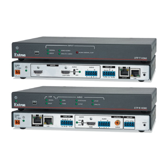
XTP T HDMI and XTP R HDMI • Setup Guide
This guide provides instructions for an experienced installer to install and connect the Extron XTP T HDMI transmitter and XTP R HDMI receiver.
Transmitter Connections
a
DC power connector
b
HDMI input connector
c
HDMI Loop-thru connector
d
Analog audio input connector
e
RS-232/IR Over XTP
connector
f
XTP output connector
g
LAN connector
Installation
Step 1 — Mounting
Turn off or disconnect all equipment power sources and mount the transmitter and receiver as required.
Step 2 — Connecting inputs
Connect a digital video source to the female HDMI connector of the XTP T HDMI (see
a.
appropriate adapter), or DisplayPort video signals.
NOTES:
•
Use an Extron LockIt
•
Video input from a DisplayPort source must be a dual mode DisplayPort source.
b.
Connect a digital video display to the HDMI loop-thru connector on the transmitter to locally display the input source. Displays that are not
HDCP compliant display a green screen when HDCP encrypted content is sent to them (see
c.
Connect balanced or unbalanced stereo audio to the
3.5 mm, 5-pole captive screw connector (see
Step 3 — Connecting Throughput Devices
a.
Connect a twisted pair cable between the XTP connectors on
the transmitter and receiver (see
ATTENTION:
Do not connect these connectors to a computer data or telecommunications
network.
The XTP T HDMI and XTP R HDMI are compatible with CAT 5e, 6, 6a, and 7 shielded twisted pair
(F/UTP, SF/UTP, and S/FTP) and unshielded twisted pair (U/UTP) cable. Extron recommends using
the following practices to achieve full transmission distances up to 330 feet (100 m) and reduce
transmission errors.
Use Extron XTP DTP 24 SF/UTP cable for the best performance. If not using XTP DTP 24
z
cable, at a minimum, Extron recommends 23 AWG, solid conductor, STP cable with a minimum
bandwidth of 400 MHz.
Terminate cables with shielded connectors to the TIA/EIA T 568 B standard.
z
Limit the use of more than two pass-through points, which may include patch points, punch
z
down connectors, couplers, and power injectors. If these pass-through points are required, use
CAT 6 or 6a shielded couplers and punch down connectors.
NOTE:
When using CAT 5e or CAT 6 cable in bundles or conduits, consider the following:
•
Do not exceed 40% fill capacity in conduits.
•
Do not comb the cable for the first 20 m, where cables are straightened, aligned, and secured in tight bundles.
•
Loosely place cables and limit the use of tie wraps or hook and loop fasteners.
•
Separate twisted pair cables from AC power cables.
Signal LED — Lights on the transmitter when it is transmitting a video signal or a test pattern. Lights on the receiver when it receives an
active XTP input signal from the transmitter.
Link LED — Lights yellow when a valid link between an XTP input and output is established.
Receiver Connections
h
DC power connector
i
XTP input connector
j
LAN connector
k
RS-232/IR Over XTP connector
l
HDMI output connector
m
Analog audio output connector
n
S/PDIF audio output connector
o
Relay connectors
Locking Bracket to secure HDMI cables to the connectors.
®
d
above).
f
i
and
above).
a
b
POWER
INPUTS
12V
1.0 A MAX
HDMI
XTP T HDMI Rear Panel
h
i j
SIG
LINK
POWER
12V
1.0 A MAX
XTP IN
LAN
XTP R HDMI Rear Panel
b
above). It can accept HDMI, DVI (with an
c
Tip
Ring
Sleeve
Sleeves
Tip
Sleeve
Ring
Balanced Stereo Input
Product Category
c
d
e
f
SIG
AUDIO
OVER XTP
AUDIO
ON
L
R
RS-232
IR
OFF
LOOP-THRU
+
−
+
−
Tx
Rx
G
Tx
Rx
XTP OUT
k
l
m n
OUTPUTS
OVER XTP
AUDIO
AUDIO
L
R
RS-232
IR
ON
OFF
+
-
+
-
Tx
Rx
G
Tx
Rx
HDMI
S/PDIF
above).
Tip
Tip
Do not tin the wires!
Unbalanced Stereo Input
Pins:
TIA/EIA T 568 B
12345678
Pin
Wire Color
Pin
1
White-orange
1
White-green
2
Orange
2
Green
3
White-green
3
White-orange
4
Blue
4
Blue
5
White-blue
5
White-blue
6
Green
6
Orange
7
White-brown
7
White-brown
8
Brown
Insert Twisted
8
Brown
Pair Wires
RJ-45
Connector
g
LINK
RESET
LAN
o
RELAYS
1
2
RESET
T568A
T5
Wire color
Wir
White-o
Orange
White-g
Blue
White-b
Green
White-b
Brown
1
Advertisement
Table of Contents

Related Manuals for Extron electronics XTP T HDMI


Summary of Contents for Extron electronics XTP T HDMI
- Page 1 Product Category XTP T HDMI and XTP R HDMI • Setup Guide This guide provides instructions for an experienced installer to install and connect the Extron XTP T HDMI transmitter and XTP R HDMI receiver. Transmitter Connections Receiver Connections DC power connector...
- Page 2 S/PDIF LED — Lights when the input audio format is multi-channel (except HBR) or LPCM-2Ch. Analog LED — Lights when the input audio format is LPCM-2Ch. 68-1723-50 © 2013 Extron Electronics — All rights reserved. All trademarks mentioned are the property of their respective owners. www.extron.com Rev. A...
Need help?
Do you have a question about the XTP T HDMI and is the answer not in the manual?
Questions and answers