EOS EmoTouch 3 Installation And Operation Manual
Control unit for sauna and steam room
Hide thumbs
Also See for EmoTouch 3:
- Installation and operation manual (55 pages) ,
- Operating instructions manual (112 pages) ,
- Installation instructions for retailers (72 pages)
Table of Contents

Related Manuals for EOS EmoTouch 3


Summary of Contents for EOS EmoTouch 3
- Page 1 I N N O V A T I V E S A U N A T E C H N O L O G Y EmoTouch 3 control unit for sauna and steam room Installation and operation manual Made in Germany Firmware R2.18...
-
Page 2: Table Of Contents
English Contents Preface and general information about sauna bathing ................4 General safety precautions ..........................5-6 Scope of delivery ..............................7 Accessories ................................8 Technical data ..............................9-10 Intended use ................................10 Installation ................................ 11-18 Main electronic unit ............................11 Display panel ..............................13 Installation of the temperature sensor ....................17 Electrical connection............................. - Page 3 Service ................................47-55 Service and Setup ............................47 Symbol overview ............................48 Settings ................................49 Troubleshooting (error messages) ........................56 Export operating data ............................57 The “switch-off“ rocker switch ..........................58 Recycling ..................................59 Service Address ..............................59 General Terms and Conditions of Service .....................60...
-
Page 4: Preface And General Information About Sauna Bathing
Preface Dear customer, quickly and easily find your way though the programming process. Please note the varia- you have purchased a high-quality electronic tion in temperatures in the cabin while sauna device with which you will enjoy your sauna bathing. The hottest area is directly below the &... -
Page 5: General Safety Precautions
General safety precautions be held within operating parameters and a minimal deviation at the bench level of This device may be used by children (age • the sauna cabin can be achieved only if the 8 and above) and by persons with reduced device is installed correctly. - Page 6 ! Attention! When designing the sauna cabin, en- sure that the external exposed glass surfaces Dear customer, may only reach a maximum temperature of according to the valid regulations, the 76 °C. If necessary, protective features need electrical connection of the sauna heater to be fitted.
-
Page 7: Scope Of Delivery
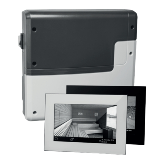
Scope of delivery (changes are reserved) Main electronic unit (with two-part front cover) Control panel with touchscreen display Housing base for flush-mounted installation of the control panel, with mounting brackets De-installation tool (for display panel) Temperature sensor: a) housing, b) sensor board, c) overheat protection fuse, d) 2 mounting screws 4 x 40 mm, e) connection cable 5 m with RJ10 plug, f ) 2-core white cable for over heating protection fuse 5 m Connection cable 5 m (main unit - touch screen display) with RJ14 / RJ10 plugs... -
Page 8: Accessories
Item no. 94.6285 Connection cable Sauna Bus 10 m (RJ12/RJ12) Item no. 94.5861 Connection cable Sauna Bus 25 m (RJ12/RJ12) Item no. 94.4647 Connection cable Sauna Bus 50 m (RJ12/RJ12) Item no. 94.4648 Power adapter for Bus-cable EmoTouch 3 Item no. 94.6671... -
Page 9: Technical Data
Technical data Voltage (power supply): 400 V 3 N AC 50 Hz Switching capacity: max. 9 kW resistive load, may be extended with a power extension unit (LSG). Fuse 3 x 16 A Heating time limit: 6 h / 12 h / unlimited Housing: plastic, shatter-resistant Display:... -
Page 10: Intended Use
Terminal block WM, 3, 4, light, fan: 0,34-2,5mm² rigid or flexible crimped wire. Please observe the minimal cross section as per fuse protection of the line! Card reader: Micro-SD card reader in control panel Ambient temperatures: -10 °C bis +35 °C Storage temperatures: -20 °C bis +60 °C Place of installation requirement: Intended for indoor installation only. -
Page 11: Installation
Installation of the main electronic unit The main electronic unit (relay box) may be installed only outside the sauna cabin. The recom- mended places of installation are the outer sauna wall or the engineering room (plant room). If empty ducts for connection cables are already available, then they usually predetermine the in- stallation position. - Page 12 Hang the housing on the upper central screw in the upper central mounting hole. Insert the supplied rubber cable glands into the openings of the bottom of the housing (from below or from behind, as desired) and then guide the connection cables through these open- ings.
-
Page 13: Display Panel
Installation depth - min. 35 mm required. the display panel is 50 m. If the cable length Lay the connection cable from the relay is over 25 m, an EmoTouch 3 power adaptor box to the display panel. is required. - Page 14 IMPORTANT NOTES Maximum connection line length for the display panel is 50 m. For cable lengths over 25 m, an EmoTouch 3 power adaptor (optional accessory, Item no. 94.6671) is required. The smaller RJ10 plug of the connection cable must be routed to the display panel.
- Page 15 Flush-mounted installation (wall-mounting) Installation of the housing base First install the housing base (see fig. 7). 1. Loosen 4 screws on the fastening brackets 2. Pull the connection cable through the cable duct in the housing base. 3. Insert the housing base into the wall opening. 4.
- Page 16 Display panel installation Place the display panel directly in front of the housing base and pay attention to the correct orien- tation. The display panel should be connected to the relay box as described in the overview. Pay attention to the correct routing of the connection cable(s). Now carefully press the display panel into the housing base until you hear a clicking sound (hooks of the upper part should snap into the holders in the base).
-
Page 17: Installation Of The Temperature Sensor
Connection of sensor cables Do not lay sensor and power supply lines together, or lead them through the same duct. This can lead to interferences in the electronics, such as “fluttering” in the relays. Connect the cable shield- ing (if present) to ground in the control unit. Please observe that the following dimensions relate to the values stipulated during the unit in- spection acc. - Page 18 Lead the sensor cable (red) and the limiter cable (white) through the drilled hole and connect both cables to the main relay box. Connect the sensor cable to the sensor board according to fig.15. Make sure the connections are correct. Connect the limiter cable (2-core white cable) to the limiter board (STB). Mount the sensor to the ceiling plank using two supplied screws and attach the housing cover.
-
Page 19: Electrical Connection
Electrical connection Sauna heater connection The electrical connections may only be car- ried out by a certified electrician in compli- Install the sauna heater and the vaporizer (if ance with the guidelines of the local power available) inside the sauna cabin in front of the supply company and applicable legal regu- air intake according to the manufacturer’s in- lations (e.g. -
Page 20: Connection Of Sauna Lamp
Sauna lamp connection Heating time limitation The max. heating time may be limited with the jumper #5 on the main board of the relay box. The sauna lamp must have the protection The limitation may be set to 6 hours, 12 hours class of at least IPx4 and should be resistant to or to unlimited. -
Page 21: Overview And Terminal Layout
Saunabus of the heater is turned light S1 S1 N L1 L2 L3 N W V U N EmoTouch 3 L N L N Bedienteil Control panel Tableau de commande off, i. e. the heating load is not symmetri- cal. -
Page 22: Overview - Connection Of Temperatur-, Humidity- And Bench Sensor
Temperature sensor ! ATTENTION! Feuchtefühler Humidity sensor Bankfühler Connecting a sensor to the sauna bus 2nd sensor Ofenfühler reserviert (RJ12 jack) may damage the sensor and Main sensor reserved the main board of the control unit!! Sensorbus RJ 10 The sensors are connected via RJ10 modular plugs to one of the corresponding sensor bus Saunabus RJ10 jacks on the main board of the relay box,... -
Page 23: Humidity Sensor Installation
Humidity Feuchtefühler Humidity sensor Bankfühler sensor installation 2nd sensor Ofenfühler reserviert Main sensor reserved Sensorbus RJ 10 1. The humidity sensor shall be mounted in the Connection over- middle of the wall opposite to the heater at view of tempera- Saunabus ture sensor, bench approx. -
Page 24: Installation Of The Optional Bench Sensor
Installation of the The sensor symbol will be displayed either on the start screen (Emotec, EmoStyle models) or optional bench sensor in the temperature query submenu (EmoTouch models). If the bench sensor is faulty, the temperature Place of installation: The 2nd sensor (bench will be controlled via the main sensor over the sensor) shall be mounted to the ceiling, over heater. -
Page 25: Vaporizer Connection
Vaporizer connection ! Attention: Always connect the neutral (N) terminal at the sauna heater. In humid mode one phase will be switched off, the Only for “H“ series sauna control units. power load distribution will not be propor- tional. As a result the N line will not be cur- ATTENTION: pay particular attention to rentless. -
Page 26: Setup (Commissioning / First Switching)
Setup (commissioning / first switching) Using the control unit for the first time or after a reset The EmoTouch 3 control unit offers a fast and intuitive setup upon the first switching or after a full system reset. Select language... - Page 27 3. Select between private or commercial use Select the applicable option and touch it again to confirm: for private use, or for commercial use 4. Safety system for saunas as per norm EU 60335 available? Select the applicable option and touch it again to confirm: - yes or - no.
- Page 28 Einstellungen Settings Select Cabin Auswahl Kabinen 07. Dezember 2016 31. November 2016 14:22:38 08:44:40 Example Example Display in stand-by mode with only one cabin (sauna design Display in stand-by mode with several connected cabins may differ). (cabin design may differ for each cabin). Control of several cabins from one display panel In order to control several cabins from one display panels, these cabins should be connected and properly configured.
-
Page 29: Multi-Cabin Connection
Connection for multi-cabin control Regardless of whether you use the EmoTouch 3 as a control unit for sauna, steam bath or for sev- eral cabins, the connection always follows the following principle: 1. - Page 30 Programming button jack cabin - address 7 cabin - address 8 Programming button in EmoTouch 3 Version SteamRock Premium Important note: Make sure that the connection order is strictly adhered to. The connection must necessarily start with the 1 jack. A cabin with the address e.g. “4” must not be connected to a jack other than No.
- Page 31 Example - connection of 8 cabins to the EmoTouch 3 display panel EmoTouch 3 Bedienteil Display panel Tableau de commande max. max. max. max. SAUNA SAUNA 9 kW 3 kW 3 kW 9 kW Saunaofen Verdampfer Verdampfer Saunaofen Sauna heater...
-
Page 32: Setup (Commissioning / First Switching)
Display with several cabins As soon as you have connected more than one cabin with the corresponding cabin address (ID) to the display panel, the multi-cabin control symbol appears in the lower bar on the display. The number inside this symbol indicates the number of the currently selected cabin. 31. -
Page 33: Operation
Operation Display panel - Overview of graphic user interface (GUI) Light Colour light for dimming Climate check (optional) touch 3 sec Sound Temperature to adjust settings touch the heater >3 sec Date and Time 31. November 2016 Cabin selection 14:22:38 (only with several cabins) On / Off Fault... -
Page 34: Operating Principle
Operating principle of the graphic user interface Briefly touch to select or enable any of the functions available on the graphical user interface (cab- in icon). Keep touching a function (>3 sec) to access the associated settings screen. For safety reasons, you should always press certain symbols / icons for more than 3 sec (e. -
Page 35: Symbol Description - Extended Settings
PIN-code input is requested. ! ATTENTION Make sure that the applied PIN-code is not lost or forgotten. Otherwise you can no longer use the locked device! If the entered code is no longer available, please contact your dealer or the EOS Service. -
Page 36: Graphic User Interface And Climate Conditions Check
Graphic user interface (GUI) and climate conditions check Thanks to the modern GUI, you can quickly make all settings on the display, as well as query the current climate conditions while the sauna is running. The symbols on the start screen are displayed in different colours, to indicate the current operation status - e. -
Page 37: Operation And Program Settings
Operation and program settings Switching the heating On / Off Press the symbol for approx. 3 seconds. The heating will switch on and the display will show the active heating mode. The light will be also switched on. To switch the sauna off, shortly touch the symbol again. - Page 38 and below the characteristic curve (see table above). For example, at 60 °C you can set up to 40 % rel. humidity. Light On / Off Shortly touch the lamp on the display to switch the light on or off. - light off, - light on.
- Page 39 • Set the desired start time using the “+“ and “-“ buttons. Settings • Confirm your setting with the green check symbol. Timer • The programmed start time will appear flashing in the bot- Auto-Start tom line on the screen. The set time corresponds to the real time, not the time delay from the moment of setting.
- Page 40 • Set the desired stop time (hours and minutes) - e. g. 19:30. • Set the desired temperature (with humid operation - humidity as well). After the last step, tap on overview of the weekday. The day on which you have set a program is displayed in blue.
-
Page 41: Extended Settings
Extended settings Settings For private use briefly touch the symbol to display the Extended Settings menu. For commercial use press >3 sec on this symbol 5645 and enter the access code to open the Ex- tended Settings menu. 31. Oktober 2016 14:22:38 In the submenu “Extended Settings”... - Page 42 Make sure that the applied PIN-code is not lost or forgotten. Otherwise you can no longer use the locked device! If the entered code is no longer available, please contact your dealer or the EOS Service. Heating time (Auto-Stop) Here you can set the required heating time duration for your sauna heater.
- Page 43 ! ATTENTION Make sure that the applied PIN-code is not lost or forgotten. Otherwise you can no longer use the locked device! If the entered code is no longer available, please contact your dealer or the EOS Service.
- Page 44 Potential-free contact With the function “potential-free contact” you can use the corresponding symbol on the start screen to switch an external device or a func- tion (e. g. additional light, etc.). Touch the potential-free contact symbol make the desired switching (on or off ). If the potential-free contact symbol does not appear, contact your dealer or installer to en- 31.
-
Page 46: Manual Setting Of The Lamp
Manual setting of the lamp The control unit is factory set to inductive lighting load. Hence, resistive loads can also be con- trolled. If required, the light output can also be switched manually to capacitive loads. When using incandescent lamps, the lighting load must remain set to inductive load. The current setting is shown on the display. -
Page 47: Service
Service and Setup The EmoTouch 3 provides an extensive scope of functions for setup and fine-tuning of the sauna equipment, in order to optimize sauna operation. This setup menu is protected with a PIN-code and should not be accessible to the end users. -
Page 48: Symbol Overview
Symbol overview of the service area Service / maintenance intervals Afterheating time Setting the intervals for service / maintenance. Setting for humid operation in minutes. Only for Bi-O mode. Firmware Update Afterheating temperature Firmware update possibility for display panel, Setting for humid operation in °C. relay box or colour light module. -
Page 49: Settings
5-6 sec. until the PIN-code prompt appears and enter the access code 543210. The update menu will be launched directly. ! Notice: Make sure that the power supply is not interrupted during the update process! Otherwise the device may become unusable. In this case, contact EOS Technical Support. - Page 50 ! Notice: Do not try to update the firmware without appropriate qualification! In the case of power supply loss, the device will attempt to resume the update process. If resuming the update fails or the display shows an error message, press the “Reset” button on the board next to the cell battery.
- Page 51 Potential-free contact The terminals 3 and 4 on the main board of the relay box are a “NO / normally open” potential-free contact of a relay on this board. This output is not linked to any other connection and is therefore potential-free.
- Page 52 Switching “off” if there is water shortage in the vaporizer (only for Bi-O heaters) Switching for an additional vaporizer (synchronisation of switching with the output WB, only for Bi-O heaters) > 50° Switching “on“ if the current temperature reaches 50 °C. <...
- Page 53 Refilling time Here you can set the grace time which the end user has to refill the vaporizer after the water short- age alarm. If the vaporizer has not been refilled within this time, it will be switched off (overheating protection).
- Page 54 The HOT symbol will appear flashing in the bottom line to indicate the function is active. Once activated the HOT function cannot be stopped. 00:20 HOT-submenu settings Einstellungen HOT Laufzeit HOT-runtime • In this menu the duration is set for which the heater heats up to 115° C •...
- Page 55 ECO is an energy-saving function, which reduces the sauna temperature to a lower level which allows to reduce the energy consumption while still keeping sauna warm, so that it can return to normal temperature level in a short time. ECO function is available for dry (Finnish) and humid (Bi-O) sauna mode. ECO function can be launched from the display panel or with the optional ECO push button (Item no.
-
Page 56: Troubleshooting (Error Messages)
Troubleshooting (error messages) EmoTouch 3 is able to detect various disruptions and errors and displays them as symbols or text messages. With only one connected cabin, the error message will be shown directly on the display. With multi-cabin control, the error messages will be shown in the lower bar with the symbol. -
Page 57: Export Operating Data
Export operating data The operating data - if a mass storage device is available - is automatically written to the mass storage device with every error message. 1. Disconnect the device from the mains 2. Remove the display panel (see “how to remove the display panel”) 3. -
Page 58: The "Switch-Off" Rocker Switch
The “switch-off“ rocker switch The control unit is equipped with a “switch-off” rocker switch. You will find this switch on the left side of the main relay box. This switch allows to switch the control unit to standby mode (notice the heating will not start), to switch the control unit completely off (disconnect from power) or to switch the con- rocker switch... -
Page 59: Recycling
2012/19/EU. Do not dispose it with the normal household waste. Service Address: EOS Saunatechnik GmbH Schneiderstriesch 1 35759 Driedorf, Germany Tel: +49 (0)2775 82-514 Fax: +49 (0)2775 82-431 servicecenter@eos-sauna.de... -
Page 60: General Terms And Conditions Of Service
The manufacturers General Terms and Conditions of Business, which can be found at www.eos-sauna.com/ V. Liability agb, shall apply in addition to the foregoing terms and conditions of service.
Need help?
Do you have a question about the EmoTouch 3 and is the answer not in the manual?
Questions and answers