
Related Manuals for EOS ECON I1


Summary of Contents for EOS ECON I1
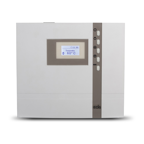
- Page 1 I N N O V A T I V E S A U N A T E C H N O L O G Y ECON I1 control unit for infrared warming cabins Installation and operating instruction Made in Germany Firmware R4.35...
-
Page 2: Table Of Contents
English Table of contents General Information ...........................4 General safety precautions ........................5 Scope of Delivery ............................7 Technical data ..............................8 Installation of the control unit ........................9 Wall installation............................9 Surface-mounted installation ......................9 Recessed installation .......................... 10 Connecting the sensor cables ....................... 11 Installation of the main sensor ......................11 Electrical connection .......................... - Page 3 Activate / deactivate the child lock ..................26 Activate / deactivate the Life - Guard ..................26 Life-Guard ..............................27 Switching on the IR unit with Life-Guard ..................28 Holiday home - Holiday park mode ..................... 29 Device fuses ..............................30 Error messages ............................
-
Page 4: General Information
Dear customer, with this IR-control unit, you have received an advanced electronic device, which was devel- oped and manufactured to meet to the highest quality and safety standards. The following operation instructions describe how to use the control unit. Read these instructions carefully and keep it for future references, in order to quickly and easily operate your infrared cabin. -
Page 5: General Safety Precautions
General safety precautions the temperature sensor. The temperature above the oven is critical for the temper- This device can be used by children aged • ature setting. The temperature can be 8 upwards and by persons with physical, held within operating parameters and a sensory, or mental disabilities, or who minimal temperature gradient inside the have inadequate experience and knowl-... - Page 6 ! Attention! Dear customer, according to current legal regulations, the electrical connection of the IR radiator and the control unit has to be carried out through the specialist of an authorized electric shop. We would like to draw your attention that in case of a warranty claim, you are kindly requested to present a copy of the invoice of the executive electric shop.
-
Page 7: Scope Of Delivery
Scope of delivery (changes without prior notice reserved) The package contents includes: 1. Control unit 2. Temperature sensor, consisiting of: sensor circuit board with overheating protection fuse, KTY- sensor, sensor housing, two 3x25 mm fastening screws and 2,0 m sensor cable. 3. -
Page 8: Technical Data
Technical data Voltage (power supply) 400 V 3 N 50 Hz AC Switch output max. 9 kW resistive load (AC1 mode). Heating time limit: 12 h Display LCD display 40 x 22 mm, graphic Dimensions (HxWxD) 220 x 250 x 67 mm Protection type IPx4 acc. -
Page 9: Installation Of The Control Unit
Installation of the control unit Fasten the housing bottom at the two bot- tom openings (Fig. 4) firmly to the cabin wall. Wall installation The control unit may only be mounted outside the IR-cabin. It is advisable to select the out- side wall of the cabin to which the IR-radiator ca. -
Page 10: Recessed Installation
Recessed installation 1. Cut out a wall section that is at least 3.5 cm deep according to the dimension in Fig. 5. 21 cm Fig. 5 Insert the supplied rubber grommets into the openings at the rear wall of the housing and insert the connecting cables through these openings. -
Page 11: Connecting The Sensor Cables
Connecting the sensor cables 2. Drill a hole to lead the cable through, prefer- ably through the middle of one of the wood- You should not install sensor and power supply en boards. lines together, or lead them through the same 3. - Page 12 Hole in the ceiling panel cabin ceiling Centre sensor housing on middle section Sensor cables Fig. 10 by use of screen-protected sensor cables connect ground Incorrect connection at the con- Attention! 142°C nector X2 will cause the fuse F2 to blow (see chapter „Errors“...
-
Page 13: Electrical Connection
Electrical connection Installation of IR-radiator The electrical connection may only be done by a certified electrician in compliance with • Install the IR-radiator in the cabin as per the the guidelines of the local utility company appropriate installation manual. and the VDE. •... -
Page 14: Installation Diagram
Installation diagram ECON 400 V 3 N AC 50 Hz Terminal arrangement on the circuit board Plug for sensor connection L1 L2 L3 N W V U N N terminal only for light output! -
Page 15: Connection Diagram For Ir-Radiators
Connection diagram for IR-radiators 139°C ECON L1 L2 L3 Limiter weiß / white Sensor rot / red max. 100 W 400 V 3 N AC 50 Hz If you use this device with single phase with max. 3kW, the power supply must be connected to terminal and the load to output... -
Page 16: Operation
Operation Once the system has been installed with all components and the front cover has been fixed, you can put the control unit into operation. Over the following pages we will show you the options provided to you with the control. General information The user interface MODE... -
Page 17: Default Display Stand-By
Default display Stand-by is shown if the system is in Stand-by mode. The system also returns to this screen from Temperature other menu items, if there is no activity for >15 50°C seconds. Default display in operation is displayed when the system is operational. 1 2 : 0 0 The display changes between the set tempera- Temperature... -
Page 18: Symbol Description
Symbol description 12:00 The following is shown in the top area of the display: • Light switches on automatically when heating is switched on Light symbol • Light stays on 30 min. after the heating stops • Manual light switching is possible at any time •... -
Page 19: Operation Principle
Operation principle For settings press shortly the -button. 1 2 : 0 0 MODE Temperature Use the - buttons to navigate to the 50°C required parameter which you would like to adjust. Temperature Parameter values that flash on the display can be changed and are shown in this manual as displayed. -
Page 20: Initial Commissioning
Initial commissioning Set language (DE, GB, IT, NL, PL, RU, FR, SE, ES, CZ, FI, SLO) 12:00 12:00 MODE > 3 Sec Set time of day (0:00 bis 23:59) 00:00 00:00 Time of day Time of day : 00 : 00 MODE 00:00 00:00... -
Page 21: Switching The Ir-Unit On / Off
Switching on the IR-unit 1 2 : 0 0 1 2 : 0 0 1 2 : 0 0 Temperature Temperature Auto-Stop 50°C 50°C 5:59 > 3 sec Switching off the IR-unit 1 2 : 0 0 1 2 : 0 0 1 2 : 0 0 Temperature Auto-Stop... -
Page 22: Individual Settings
Individual settings The following are options for adapting the control systems to your individual needs. The param- eters can be adjusted both in stand-by or in operation mode and the changes are then saved in the device. Changes made in operation mode will apply immediately, once saved. Cabin temperature Setting range: mode 30 - 70°C... -
Page 23: Auto-Stop / Heat-Up Time Limitation
Auto-stop / heat-up time limitation Auto-Stop defines the heating time limitation. The IR-unit automatically turns off once this time has expired. A time between 0:30 to 12:00 can be set. In Stand-by In operation 1 2 : 0 0 1 2 : 0 0 1 2 : 0 0 Temperature Temperature... -
Page 24: Cabin Lighting
1 2 : 0 0 1 2 : 0 0 Auto-Stop Auto-Stop 3:30 3: 30 > 3 sek. MODE MODE > 3 sek. 1 2 : 0 0 1 2 : 0 0 Temperature Auto-Stop 50°C 3:30 15 sek. > 3 Sek 1 2 : 0 0 1 2 : 0 0 Temperature... -
Page 25: Advanced Settings
Advanced settings Change language Change time 1 2 : 0 0 1 2 : 0 0 Temperature Temperature 50°C 50°C & MODE & MODE 12:00 12:00 Time of day Time of day 12 : 30 12 : 30 MODE 12:00 12:00 Time of day 12 : 30... -
Page 26: Activate / Deactivate The Child Lock
Activate / deactivate the child lock Activate / deactivate the Life - Guard If the child lock is activated (the key symbol is Life - Guard is a settable, relatively short time, visible in the top section of the display) only the e.g. -
Page 27: Life-Guard
Life-Guard Here you can set a short period of time after which the unit will be automatically switched off (interrupted) and may be immediately restarted for the same period of time by pressing the MODE button. For example, set up 15 minutes. If you do not press the button again after 15 minutes, the unit will switch off. -
Page 28: Switching On The Ir Unit With Life-Guard
Switching on the IR unit with Life-Guard 1 2 : 0 0 Temperature 50°C > 3 Sek 1 2 : 0 0 1 2 : 0 0 Temperature Auto-Stop 50°C 5 : 59 The IR-radiator is now heating normal, with- out “Life-Guard”-time. -
Page 29: Holiday Home - Holiday Park Mode
Holiday home mode Holiday park mode Symbol flashes The holiday home mode allows the control In the holiday park mode, all functions are de- system to be blocked so that only the most es- activated apart from Infrared and Light (On/ sential functions are visible and can be set. -
Page 30: Device Fuses
Device fuses The control unit is fitted with two protective fuses which are mounted on the main relay board of the unit. These fuses protect the electronics on the board and the light and fan outputs. Notice: fuses do not mean absolute protection, in an unlikely case of a power surge or a short circuit with particularly fast voltage increase the electronic components may be still be affected. -
Page 31: Error Messages
Error messages The control unit continuously monitors the sensor for short circuits and interruptions. The error messages appear as follows: Display Cause Remedy = interrupted room sensor circuit Arrange for a specialist to 12:00 The temperature sensor (KTY) is check the lines and KTY. faulty, or the line to the temperature Sensor - KTY at 20°C approx. -
Page 32: The Device „Switch-Off" Switch
The device „Switch-off“ switch The control unit is equipped with a “Switch-off” Switch-off rocker rocker switch. You will find this switch on the top side of the housing by Econ series control units. This switch allows to switch the control unit to the standby mode (notice the heating will not start), to switch the control unit completely off (disconnect from power) or to switch the con-... -
Page 33: Recycling
2012/19/EU. Do not dispose it with the normal household waste. Service Address: EOS Saunatechnik GmbH Schneiderstriesch 1 35759 Driedorf, Germany Tel: +49 (0)2775 82-514 Fax: +49 (0)2775 82-431 servicecenter@eos-sauna.de... -
Page 34: General Terms And Conditions Of Service
The manufacturers General Terms and Conditions of Business, which can be found at www.eos-sauna.com/ V. Liability agb, shall apply in addition to the foregoing terms and conditions of service.
Need help?
Do you have a question about the ECON I1 and is the answer not in the manual?
Questions and answers