
Related Manuals for EOS ECON H2


Summary of Contents for EOS ECON H2
- Page 1 ECON H2 Assembly and operating instruction Made in Germany IP x4 Druck Nr. 29344328en/ - 30.12...
-
Page 2: Table Of Contents
English Table of Contents Package contents ....................4 Technical data ......................4 General information concerning sauna bathing ............5 General safety precautions ..................6 Installation of the control unit ...................7 Wall mount fixture ....................7 Wall mounting ......................7 Wall recessing .....................8 Connecting the sensor cables ................9 Installation of the heater sensor ................9 Electrical connection ....................11 Connecting a load switch (LSG) ................11... - Page 3 Finnish mode ....................21 Switching on the sauna unit with Life - Guard..........21 Individual settings ....................22 Cabin temperature ..................22 Humidity operation ..................23 Humidity intensity ..................24 Switching off the sauna unit during humidity operation .........25 Auto-Stop ......................26 Preselection time ..................28 Activate the preselection time ...............29 Deactivate the preselection time ..............29 Life - Guard ....................30 Extend the time setting for sauna time ..............31...
-
Page 4: Package Contents
Package contents (subject to change) Included with the control unit are 1. an oven-sensor board with overheat shutoff protection, KTY-sensors with sensor housing, two 3x25 mm fastening screws and a 2,0 m long sensor cable. 2. a plastic bag with three 4 x 20 mm fastening screws. 3. -
Page 5: General Information Concerning Sauna Bathing
General information concerning sauna bathing Dear customer, with purchase of this sauna control unit you For the cabin light use only light bulbs. Do opted for a superior quality, high-tech elec- not use fl uorescent lamps, energy saving tronic device which was developed and ma- lamps and gas discharge lamps. -
Page 6: General Safety Precautions
General safety precautions • his device has not been designed for being • Please note the safety and installation in- used by persons (including children) that formation from the sauna oven manufac- are physically or mentally handicapped turer. or have sensory disabilities. Moreover, it •... -
Page 7: Installation Of The Control Unit
Installation of the control unit Fasten the housing bottom at the two bot- tom openings (Fig. 4) fi rmly to the cabin Wall mount fi xture wall. The control unit may only be mounted outside the cabin. It is advisable to select the outside wall of the cabin to which the sauna heater is fi... -
Page 8: Wall Recessing
Wall recessing 1. Cut out a wall section that is at least 3.5 cm deep according to the dimension in Fig. 5. Fig. 5 Insert the supplied rubber grommets into the openings at the rear wall of the housing and insert the connecting cables through these openings. -
Page 9: Connecting The Sensor Cables
Connecting the sensor cables 2. Drill a hole to lead the cable through, pref- erably through the middle of one of the You should not install sensor and power sup- wooden boards. ply lines together, or lead them through the 3. - Page 10 Hole Sauna ceiling Centre sensor hous- ing on middle section Sensor cables Fig. 11 142°C Sensor Limiter White Fig. 12 6. After completed installation and cor- rect operation of the control unit, the line 12:00 for overtemperature protection must be checked for short-circuits.
-
Page 11: Electrical Connection
Electrical connection Connecting the vaporizer The electrical connection may only be done by a certifi ed electrician in compli- ance with the guidelines of the local utility To connect the vaporizer, use silicone con- company and the VDE. necting lines 4 x 1,5 mm² as well. In general, there may be only one fi... -
Page 12: Installation Diagram
Installation diagram = alternativ oder ECON max. 3 kW 400 V 3 N AC 50 Hz Terminal arrangement on the circuit board. Plug for sensor connection u n d e r - neath the c i r c u i t board... -
Page 13: Connecting The Sauna Heater (Max. 9 Kw)
Connecting the sauna heater (max. 9 kW) ECON L1 L2 L3 max. 100 W max. 100 W P max. 9 kW max. 3000 W Warning: Always connect the neutral conductor of the 400 V 3 N AC 50 Hz sauna oven. During steam operation, one phase of the oven is shut down;... -
Page 14: Connection Of Vaporizer
Connection of vaporizer ECON L1 L2 L3 CAUTION When connecting the vaporizer the output “W” is switched from the sauna heater to the terminal “Wb” to the vaporizer. In this case, the sauna heater heats only with two thirds of the power. max. -
Page 15: Operation
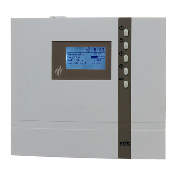
Operation Once the system has been installed with all components and all covers have been fi xed, you can put your sauna unit into operation. Over the following pages we will show you the options provided to you with the control. General The user interface Operating buttons... -
Page 16: Default Display Stand-By
Default display Stand-by is shown if the system is in Stand-by mode. 12:00 Reset to this display takes place from other Temperature 30°C Humidity menu items if no activity is carried out > 15 s. Auto-stop 5 : 59 - - : - - Start time Default display in operation is shown if the system is in operation. -
Page 17: Cabin Lighting
In order to adjust the individual values to the particular desires, briefl y push the MODE -button out of Stand-by. 12:15 Temperature 30°C The modifi able parameter will then be high- Humidity lighted in black and it is possible to select Auto-stop 5 : 59 - - : - -... -
Page 18: Initial Commissioning
Initial commissioning 12:00 12:15 Life - Guard 12:00 12:15 Life - Guard > 3 s MODE 00:00 Time of day > 3 s MODE : 00 12:00 Temperature 30°C Humidity Auto-stop 5 : 59 - - : - - Start time 00:00 Time of day : 00... -
Page 19: Change Language
Change language Change time 12:00 12:00 Temperatur 30°C Temperature 30°C Feuchte Humidity Auto-Stop 5 : 59 Auto-stop 5 : 59 - - : - - - - : - - Vorwahlzeit Start time & & MODE MODE 12:00 12:15 Time of day Tageszeit 12 : 00 12 : 15... -
Page 20: Activating The Life - Guard
Activating the Life - Guard Activate / deactivate the child lock Life - Guard is a settable relatively short If the child lock is activated (the key symbol time, e.g. 20 minutes, after which the sauna is visible in the top section of the display) unit is switched off, except for the cabin light- only the cabin lighting can be switched. -
Page 21: Switching On The Sauna Unit
Switching on the sauna unit Switching on the sauna unit with Life - Guard 12:00 12:00 Temperature 30°C Temperature 30°C Humidity Humidity Auto-stop Auto-stop 5 : 59 5 : 59 - - : - - - - : - - Start time Start time 20 min... -
Page 22: Individual Settings
Individual settings Hereafter we are showing you options that allow you to adjust the controls to your individual needs. The various parameters can be changed in Stand-by or in operation and the changes are saved in the unit. Changes made in operation are effective directly. Setting range: Finnish mode 30 - 115°C Cabin temperature Humidity mode 30 - 70°C... -
Page 23: Humidity Operation
Humidity operation perature sinks towards the cabin fl oor. The following diagram shows you the rela- tive air humidity temperature values for the standard bath forms and comfort zones. The prerequisite for humidity operation is the connection of a suitable evaporator unit up to max. -
Page 24: Humidity Intensity
Humidity intensity If a value is entered here the sauna unit automatically goes into humidity operation when switched on. In Stand-by In operation 12:00 12:15 Temperature 30°C Temperature 30°C Humidity Humidity Auto-stop 5 : 59 Auto-stop 5 : 59 - - : - - Start time - - : - - Start time... -
Page 25: Switching Off The Sauna Unit During Humidity Operation
Switching off the sauna unit during humidity operation In order to dry out the sauna cabin after the humidity operation, a reheating phase is activated after the humidity operation is switched off. The cabin is heated here to 90°C for ca. 30 minutes. This is shown in the upper section of the display with the blink- ing symbol . -
Page 26: Auto-Stop
Auto-Stop Auto-Stop is the time to which the heating time is limited. The sauna unit automatically turns off once this time has expired. Depending on the confi guration of the control, the time is adjustable from 0:01 to 6:00 or 12:00 hours. - Page 27 12:15 12:15 Temperature 30°C Temperature 30°C Humidity Humidity Auto-stop Auto-stop - - : - - - - : - - Start time Start time > 3 s MODE > 3 s MODE 12:15 12:15 Temperature 30°C Temperature 30°C Humidity Humidity Auto-stop 3 : 30 Auto-stop...
-
Page 28: Preselection Time
Preselection time Using the time preselection, you can preselect a switch-on time within 24 hours for your sauna heater. Always make sure that there are no objects on the sauna unit before the heating process begins. Fire risk! Please remember however that the cabin must heat up for approx. 40-50 minutes in order to achieve a pleasant climate in the cabin. -
Page 29: Activate The Preselection Time
12:15 12:15 Temperature 30°C Temperature 30°C Humidity Humidity Auto-stop 5 : 59 Auto-stop 5 : 59 17 : Start time Start time 17 : 12:15 12:15 Temperature 30°C Temperature 30°C Humidity Humidity Auto-stop 5 : 59 Auto-stop 5 : 59 Start time 17 : Start time... -
Page 30: Life - Guard
Life - Guard Here you can set after what time the sauna unit is switched off and by pushing the - but- MODE ton again you can restart the „Life - Guard“ time. This setting can only be selected in Stand-by when the function „Life - Guard“ is activated. In Stand-by 12:00 12:00... -
Page 31: Extend The Time Setting For Sauna Time
Extend the time setting for sauna time By switching a jumper you can extend the time setting for sauna time from 6:00 to 12:00 hours. Such work must be left exclusively to an expert. Prior to any kind of work disconnect all poles on the opened control unit from the power supply. -
Page 32: Error Messages
Error messages The control unit continuously monitors the sensor for short circuits and interruptions. At the same time it checks if there is enough water in the evaporator container. The error messages appear as follows: Cause Display Remedy Have cables and KTY = Interruption in the room sensor circuit checked by an expert. -
Page 33: The Device Switch (Switch-Off)
The device switch (Switch-off) Unit switch The unit switch is located at the top of the control unit. You can disconnect the elec- tronics from the mains using this switch in case of a fault. Unit switch Unit switched on In case of faults push the unit switch on = Unit the left side of the rocker to the fi... -
Page 34: Service Address
Service Address: Outside of Germany please contact your EOS Saunatechnik GmbH specialist dealer in case of warranty claims. Adolf-Weiß-Straße 43 Direct warranty processing with our service 35759 Driedorf-Mademühlen, Germany department is in this case not possible. -
Page 35: Handling Procedures For Return Shipments (Rma) - Details For All Returns
Handling procedures for return shipments (RMA) - Details for all returns ! Dear customer we hope that you will rejoice in the ordered articles. Just in case that you are not entirely contented as an exeption, please follow the procedures specifi ed below.This enabling us to ensure a quick and smooth handling of the return shipment.
Need help?
Do you have a question about the ECON H2 and is the answer not in the manual?
Questions and answers
How to stary