Table of Contents
Advertisement
Quick Links
Advertisement
Table of Contents

Subscribe to Our Youtube Channel
Related Manuals for ADLINK Technology ROScube-Pico NPN Series


Summary of Contents for ADLINK Technology ROScube-Pico NPN Series
- Page 1 ROScube-Pico NPN Series User’s Manual NVIDIA® Jetson Nano™ / Xavier™ NX SOM-based platform for rapid development and deployment of ROS and AI applications Manual Rev.: Revision Date: March 29, 2022 Part Number: 50M-00015-1000 Leading EDGE COMPUTING...
- Page 2 Preface Copyright Copyright © 2022 ADLINK Technology, Inc. This document contains proprietary information protected by copyright. All rights are reserved. No part of this manual allow to reproduce by any mechanical, electronic, or other means in any form without prior written permission of the manufacturer.
-
Page 3: Table Of Contents
Table of Contents Preface ..........................ii List of Figures ........................iv List of Tables........................v Introduction........................1 Specifications ......................3 Product Specifications ....................3 Packing List ........................5 Optional Accessories ....................5 Mechanical Dimensions....................6 System Layout ......................9 Pinouts and Signal Descriptions................13 USB 3.1 Ports ......................13 Gigabit Ethernet Ports ....................14 HDMI Connector .......................16 Micro USB 2.0 OTG Connector ................16 Multi-I/O Connector (DB-37) ..................17... -
Page 4: List Of Figures
List of Figures Figure 1: Box Dimensions (top view)......................6 Figure 2: Box Dimensions (front view) .....................7 Figure 3: Box Dimensions (side view) ......................7 Figure 5: Board Dimensions ........................8 Figure 6: Front Panel I/O ..........................9 Figure 7: Right Side Panel I/O........................9 Figure 8: Left Side Panel I/O ......................... - Page 5 List of Tables Table 1: Front Panel I/O Legend ......................9 Table 2: Right Side Panel I/O Legend......................9 Table 3: Left Side Panel I/O Legend ..................... 10 Table 4: Carrier Board Connector Legend (top)..................11 Table 5: Carrier Board Connector Legend (bottom)................12 Table 6: USB 3.1 Pin Definition......................
- Page 6 This page intentionally left blank. Preface...
-
Page 7: Introduction
Introduction ADLINK’s ROScube-Pico NPN Series is a ROS 2 enabled robotic controller powered by the NVIDIA® Jetson Nano™ or Xavier™ NX system-on-module (SOM). ROSCube Pico supports a full complement of resources developed with the NVIDIA JetPack SDK and ADLINK’s Neuron SDK, and is specifically suited for robotic applications demanding high-AI computing with minimal power consumption. - Page 8 This page intentionally left blank. Introduction...
-
Page 9: Specifications
Specifications Product Specifications ROScube Pico NPN NVIDIA® Jetson Nano™ NVIDIA® Jetson Xavier™ NX Model Name NPN-1B NPN-2B System-on-Module (SOM) Module NVIDIA Jetson Nano Module NVIDIA Jetson Xavier NX module Quad-core ARM Cortex-A57 MPCore processor 6-core NVIDIA Carmel ARM v8.2 64-bit CPU 6MB L2 + 4MB L3 Power Modes (S/W controllable by user): 2-core @ 1.5GHz, 10W... - Page 10 ROScube Pico NPN NVIDIA® Jetson Nano™ NVIDIA® Jetson Xavier™ NX Model Name NPN-1B NPN-2B Side Panel I/O Interfaces 2x UART, 2x I C, 1x SPI, 1x CANbus (NPN-2B only), 5x GPIO, 1x extended power on/off, Multi-IO Connector (DB-37) 1x extended SYS reset, 1x extended force recovery Audio In/Out 1x 3.5mm stereo line-out jack Sensors...
-
Page 11: Packing List
Packing List Controller 1x ROSCube Pico Nano or Xavier NX Power Transfer Cable 1x Dinkel 2-pin to DC plug cable Wall Mount kit 2x wall mount brackets Optional Accessories M.2 NVMe SSD M.2 2242 NVMe SSD 256GB, Transcend TS256GMTE452T, for NPN-2B only (P/N: 29-46N00-6100) Wi-Fi Module Intel®... -
Page 12: Mechanical Dimensions
Mechanical Dimensions All dimensions shown in millimeters 2.4.1 External Dimensions 145.10 Figure 1: Box Dimensions (top view) Specifications... -
Page 13: Figure 2: Box Dimensions (Front View)
Figure 2: Box Dimensions (front view) 11.20 Figure 3: Box Dimensions (side view) Specifications... -
Page 14: Figure 5: Board Dimensions
2.4.2 Board Dimensions 27.28 123.5 Figure 4: Board Dimensions Specifications... -
Page 15: System Layout
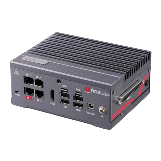
System Layout 2.5.1 External Connector Locations Figure 5: Front Panel I/O USB 3.0 Type-A ports x4 A USB 2.0 OTG port x1 (2x with lockable connectors) B Gigabit Ethernet ports x4 E DC 8–20V x1 C HDMI 2.0 port x1 F Ground Screw x1 Table 1: Front Panel I/O Legend Figure 6: Right Side Panel I/O... -
Page 16: Figure 8: Left Side Panel I/O
Figure 7: Left Side Panel I/O Audio Out x1 Reset button x1 Power button x1 Table 3: Left Side Panel I/O Legend Specifications... -
Page 17: Figure 9: Carrier Board Connectors (Top)
2.5.2 Carrier Board Connector Locations Figure 8: Carrier Board Connectors (top) DDR4 SODIMM socket for G USB 3.1 ports (4x) M Power button NVIDIA Jetson module CAN bus jumper header, RTC battery pin header (reserved - do not change H HDMI 2.0 connector (battery is glued to back of GbE ports) settings - NPN-2B only) -
Page 18: Figure 10: Carrier Board Connectors (Bottom)
Figure 9: Carrier Board Connectors (bottom) M.2 2242 Key M socket for A microSD slot NVMe module (NPN-2B only M.2 2230 Key E socket for D NVMe module LED (amber) Wi-Fi/Bluetooth module Table 5: Carrier Board Connector Legend (bottom) Specifications... -
Page 19: Pinouts And Signal Descriptions
Pinouts and Signal Descriptions USB 3.1 Ports The ROScube Pico provides 4x USB 3.1 Gen1 (2 standard, 2 lockable) via hub controller. Signal +V5P0_USB U2_ CN_D_N U2_ CN_D_P U3_ CNRX_N U3_ CNRX_P U3_ CNTX_N U3_ CNTX_P Table 6: USB 3.1 Pin Definition USB 3.1 Port Type A Speed: 5 Gbps Color: Blue... -
Page 20: Gigabit Ethernet Ports
Gigabit Ethernet Ports Four Gigabit Ethernet ports are located on the front panel. LAN 1 is provided by the Jetson module, LAN 2/3/4 are each provided by a USB-to-LAN Bridge (LAN7800). • Compliant with IEEE 802.3az Energy Efficient Ethernet • Compliant with IEEE 802.3 Ethernet •... -
Page 21: Figure 12: Ethernet And Usb Hub Configuration
Notes: LAN 1 MAC address is defined by NVIDIA module. LAN 2, LAN 3, and LAN 4 have MAC addresses provided by ADLINK. During boot up, the activity LED on LAN1 will light up for a few seconds, even if the port is not connected. This is normal behavior and does not affect the function of this product. -
Page 22: Hdmi Connector
HDMI Connector The ROSCube Pico provides one HDMI interface. It consists of an upright standard HDMI connector. The pin definition is as follows: Signal Signal HDMI1_D2_CN_P HDMI1_CK_CN_N HDMI1_D2_CN_N HDMI1_CN_CEC HDMI1_D1_CN_P HDMI1_CN_SCL HDMI1_D1_CN_N HDMI1_CN_SDA HDMI1_D0_CN_P +V5P0_HDMI HDMI1_D0_CN_N HDMI1_CN_HPD HDMI1_CK_CN_P 20…23 (Shell) Table 9: HDMI Pin Definition Micro USB 2.0 OTG Connector The ROScube Pico equipped with one Micro USB 2.0 OTG Connector. -
Page 23: Multi-I/O Connector (Db-37)
Multi-I/O Connector (DB-37) The ROScube Pico have a rich I/O for autonomous, provide UART x2, I2C x2, SPI x1, CANbus x1 (NPN-2B only), PWM x5, 1x extended power on/off x1, extended SYS reset x1,extended force recovery x1. Signal Voltage Signal Voltage PWR_BTN# 5.0 V... -
Page 24: Power Button
Power Button The ROScube Pico is equipped with a Power On/Off button. This power button only function in “Power Button Mode”, when a jumper is installed at pins 5 and 6 on the Power Management Header (see 3.14 Power Management Header on page 26). If the jumper is not installed, the device will operate in “Auto Power-On Mode.” Power Button Mode When power is connected to the DC power jack, the system can be turned on by pressing the power button. -
Page 25: Nvidia Jetson Nano / Xavier Nx Module Connector
NVIDIA Jetson Nano / Xavier NX Module Connector The ROSCube Pico provides one 260-pin DDR4 SO-DIMM socket for a NVIDIA Jetson Nano or Xavier NX module.This SO-DIMM socket is located at U1 on the carrier board. The pin definition is as follows: Odd-Pin Signal Type Even-Pin... - Page 26 Odd-Pin Signal Type Even-Pin Signal Type DP1_TXD2_N DSI_CLK_N DP1_TXD2_P DSI_CLK_P DP1_TXD3_N DSI_D1_N DP1_TXD3_P DSI_D1_P GPIO00 DP0_HPD/GPIO3_P*.0n IN/IO SPI0_MOSI DP0_AUX_N SPI0_SCK DP0_AUX_P SPI0_MISO HDMI_CEC SPI0_CS0# DP1_HPD SPI0_CS1# DP1_AUX_N UART0_TXD DP1_AUX_P UART0_RXD UART0_RTS# SPI1_MOSI UART0_CTS#/GPIO3_P*. IN/IO SPI1_SCK SPI1_MISO USB0_D_N SPI1_CS0# USB0_D_P SPI1_CS1# CAM0_PWDN USB1_D_N CAM0_MCLK...
- Page 27 Odd-Pin Signal Type Even-Pin Signal Type CAN_RX CAN_TX PCIE0_TX2_N PCIE0_RX2_N PCIE0_TX2_P PCIE0_RX2_P PCIE0_TX3_N PCIE0_RX3_N PCIE0_TX3_P PCIE0_RX3_P PCIE0_CLK_N USBSS_RX_N PCIE0_CLK_P USBSS_RX_P USBSS_TX_N PCIE1_RX0_N USBSS_TX_P PCIE1_RX0_P PCIE1_TX0_N PCIE1_CLK_N PCIE1_TX0_P PCIE1_CLK_P MOD_SLEEP# PCIE_WAKE# PCIE0_CLKREQ# PCIE0_RST# PCIE1_CLKREQ# PCIE1_RST# GBE_MDI0_N I2C0_SCL GBE_MDI0_P I2C0_SDA GBE_LED_LINK I2C1_SCL GBE_MDI1_N I2C1_SDA GBE_MDI1_P...
-
Page 28: Table 15: Nvidia Jetson Nano / Xavier Nx Module Connector Pin Definition
Odd-Pin Signal Type Even-Pin Signal Type SDMMC_DAT2 I2S1_FS SDMMC_DAT3 I2S1_SCLK SDMMC_CMD GPIO13/PWM IO/OUT SDMMC_CLK GPIO14/PWM IO/OUT I2C2_SCL SHUTDOWN_REQ# I2C2_SDA PMIC_BBAT UART2_TXD POWER_EN UART2_RXD SYS_RESET# SLEEP/WAKE# Power Power Power Power Power Power Power Power Power Power VDD_IN Power VDD_IN Power VDD_IN Power VDD_IN Power... -
Page 29: Socket Key E For Wi-Fi / Bt (2230)
3.10 M.2 Socket Key E for Wi-Fi / BT (2230) The ROSCube Pico provides one M.2 socket with E Key and a standoff for 2230 sized Wi-Fi/BT modules (Wi-Fi 5/Wi-Fi 6). This m.2 socket with E key is located at CN4 on the carrier board. The pin definition is as follows: Type Signal Signal... -
Page 30: Socket Key M For Nvme (2242)
3.11 M.2 Socket Key M for NVMe (2242) The ROSCube Pico (NPN-2B only) provides one M.2 socket with M-Key and a stand-off for 2242 sized PCIe-NVMe, utilizing one PCIe lane. This M.2 socket with M key is located at CN17 on the carrier board. The pin definition is as follows: Type Signal... -
Page 31: Fan Connector (Board Level)
3.12 Fan Connector (board level) The ROScube Pico carrier board is equipped with a 4-pin fan header with PWM and tachometer function. The fan connector is located at CN1 position on the carrier board. Signal Signal FAN_CN_PWM +V5P0_FAN FAN_CN_TACHO Table 18: Fan Connector Pin Definition 3.13 MRAA Connector (board level) MRAA connector has 40 pins and is located at CN7 on the carrier board. -
Page 32: Power Management Header (Board Level)
3.14 Power Management Header (board level) Power Management Header Module Jetson Jetson Module Jetson NX Jetson Nano Nano Header PC_LED_A PC_LED_K (+V5P0) UART2_ UART2_ 3V3_UART2_RX 3V3_UART2_TX UART2_TXD UART2_TXD LATCH_SET LATCH_SET_BUT SYS_RST# SYS_RESET* SYS_RESET* FORCE_ FORCE_ FORCE_ RECOVERY# RECOVERY* RECOVERY* PWR_BTN# SLEEP*_WAKE* SLEEP*_WAKE* Table 20: Power Management Header Pin Definition Notes:... -
Page 33: Microsd Card Slot (Board Level)
3.17 microSD Card Slot (board level) The ROScube Pico is equipped with a microSD card slot on the carrier board (see Figure 9: Carrier Board Connectors (bottom) on page 12). 3.18 RTC Battery (board level) The ROScube Pico Carrier Board is equipped with an RTC Battery CR2032 3V Li VARTA, The battery is glued to back of GbE ports. - Page 34 This page intentionally left blank. Pinouts and Signal Descriptions...
-
Page 35: Getting Started
Getting Started Connect the DC plug adapter cable Locate the DC plug adapter cable, included in the accessory box (shown below). Insert to the DC output wires of the AC adapter into the terminal block P1 as indicated: negative (black) to “-“ and positive (red) to “+”. Insert the DC plug P2 into the DC power input jack on the front panel (see Figure 5: Front Panel I/O on page 9). -
Page 36: Safety Instructions
Safety Instructions Read and follow all instructions marked on the product and in the documentation before you operate your system. Retain all safety and operating instructions for future use. • Please read these safety instructions carefully. • Please keep this User‘s Manual for later reference. •... -
Page 37: Getting Service
6450 Via Del Oro, San Jose, CA 95119-1208, USA Tel: +1-408-360-0200 Toll Free: +1-800-966-5200 (USA only) Fax: +1-408-600-1189 Email: info@adlinktech.com ADLINK Technology (China) Co., Ltd. Address: 300 Fang Chun Rd., Zhangjiang Hi-Tech Park, Pudong New Area Shanghai, 201203 China Tel: +86-21-5132-8988 Fax: +86-21-5132-3588 Email: market@adlinktech.com...
Need help?
Do you have a question about the ROScube-Pico NPN Series and is the answer not in the manual?
Questions and answers