Sign In
Upload
Manuals
Brands
ADLINK Technology Manuals
Desktop
ROScube-Pico NPN Series
ADLINK Technology ROScube-Pico NPN Series Manuals
Manuals and User Guides for ADLINK Technology ROScube-Pico NPN Series. We have
1
ADLINK Technology ROScube-Pico NPN Series manual available for free PDF download: User Manual
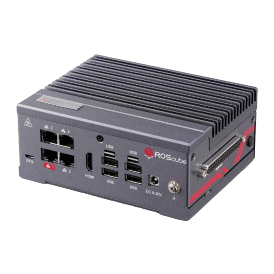
ADLINK Technology ROScube-Pico NPN Series User Manual (37 pages)
Brand:
ADLINK Technology
| Category:
Desktop
| Size: 1.01 MB
Table of Contents
Table of Contents
3
List of Figures
4
Introduction
7
Specifications
9
Product Specifications
9
Packing List
11
Optional Accessories
11
Mechanical Dimensions
12
Figure 1: Box Dimensions (Top View)
12
Figure 2: Box Dimensions (Front View)
13
Figure 3: Box Dimensions (Side View)
13
Figure 5: Board Dimensions
14
System Layout
15
Figure 6: Front Panel I/O
15
Figure 7: Right Side Panel I/O
15
Table 1: Front Panel I/O Legend
15
Table 2: Right Side Panel I/O Legend
15
Figure 8: Left Side Panel I/O
16
Table 3: Left Side Panel I/O Legend
16
Figure 9: Carrier Board Connectors (Top)
17
Table 4: Carrier Board Connector Legend (Top)
17
Figure 10: Carrier Board Connectors (Bottom)
18
Table 5: Carrier Board Connector Legend (Bottom)
18
Pinouts and Signal Descriptions
19
USB 3.1 Ports
19
Table 6: USB 3.1 Pin Definition
19
Gigabit Ethernet Ports
20
Table 7: Ethernet Port Pin Definitions
20
Table 8: Ethernet Port LED Indicators
20
Figure 12: Ethernet and USB Hub Configuration
21
HDMI Connector
22
Micro USB 2.0 OTG Connector
22
Table 9: HDMI Pin Definition
22
Table 10: Micro USB 2.0 OTG Pin Definition
22
Multi-I/O Connector (DB-37)
23
Table 11: Multi-I/O Connector Pin Definition
23
Power Button
24
Reset Button
24
DC Power Jack
24
Table 12: Power Button Mode Description
24
Table 13: DC Power Jack Pin Definition
24
Table 14: Power Source Rating
24
NVIDIA Jetson Nano / Xavier NX Module Connector
25
Table 15: NVIDIA Jetson Nano / Xavier NX Module Connector Pin Definition
28
Socket Key E for Wi-Fi / BT (2230)
29
Table 16: M.2 Socket with E Key Pin Definition
29
Socket Key M for Nvme (2242)
30
Table 17: M.2 Socket with M Key Pin Definition
30
Fan Connector (Board Level)
31
MRAA Connector (Board Level)
31
Table 18: Fan Connector Pin Definition
31
Table 19: MRAA Connector Pin Definition
31
Power Management Header (Board Level)
32
Microphone Connector (Board Level)
32
Status Leds (Board Level)
32
Table 20: Power Management Header Pin Definition
32
Table 21: Microphone Connector Pin Definition
32
Table 22: Status LED Descriptions
32
Microsd Card Slot (Board Level)
33
RTC Battery (Board Level)
33
Getting Started
35
Connect the DC Plug Adapter Cable
35
Mounting the Roscube Pico
35
Safety Instructions
36
Getting Service
37
Advertisement
Advertisement
Related Products
ADLINK Technology ROScube Pico BSP
ADLINK Technology ROScube-I Series
ADLINK Technology RTV Series
ADLINK Technology RTV-24
ADLINK Technology RTV-E4
ADLINK Technology RQI-57
ADLINK Technology RQI-53-E
ADLINK Technology ROScube-Pico TGL RQP-T37
ADLINK Technology ROScube-Pico TGL RQP-T33
ADLINK Technology ROScube-X RQX-58 Series
ADLINK Technology Categories
Computer Hardware
Motherboard
PCI Card
Control Unit
Controller
More ADLINK Technology Manuals
Login
Sign In
OR
Sign in with Facebook
Sign in with Google
Upload manual
Upload from disk
Upload from URL