Table of Contents
Advertisement
Quick Links
Advertisement
Table of Contents

Related Manuals for Custom Crimp CC4-50


Summary of Contents for Custom Crimp CC4-50
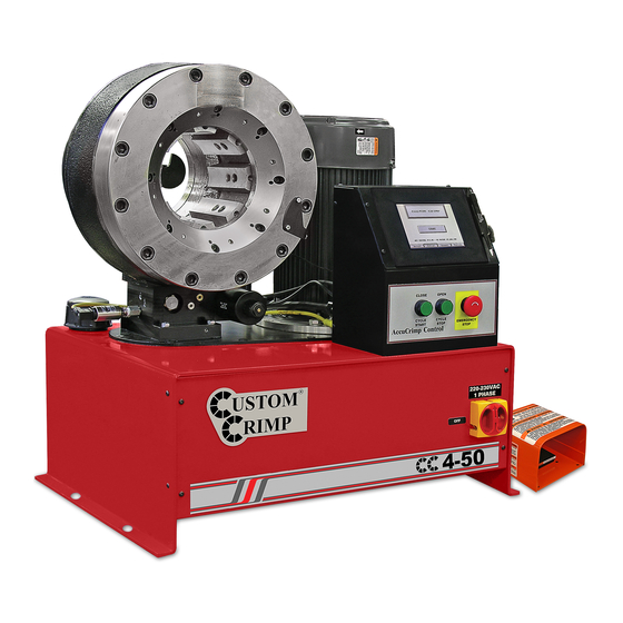
- Page 1 Page CC4-50 CRIMPER OPERATORS MANUAL...
-
Page 2: Safety Precautions
Page SAFETY PRECAUTIONS READ INSTRUCTIONS AND IDENTIFY ALL COMPONENT PARTS BEFORE USING CRIMPER KEEP HANDS AWAY FROM PINCH POINTS CONSULT HOSE AND FITTING MANUFACTURER’S SPECIFICATIONS FOR CORRECT MACHINE SETTINGS AND CRIMP MEASUREMENTS ALWAYS WEAR EYE PROTECTION For Parts and Service, Contact: Custom Machining Services, Inc. - Page 3 CRIMPER COMPONENT PARTS Page AccuCrimp CONTROL CRIMPER HEAD PANEL -SEE SEPARATE PAGE OIL FILLER CAP MASTER POWER SWITCH OIL LEVEL SIGHT GLASS FOOT SWITCH PLUG IN PORT FOOT SWITCH TANK DRAIN AND OIL COOLER PORTS...
- Page 4 CRIMPER SPECIFICATIONS & SET UP Page SPECIFICATIONS: MAX HEAD OPENING W/O DIES..............168 MM (6.62 IN) MASTER DIE INSIDE DIAMETER..............130 MM (5.11 IN) MAXIMUM SWAGING RANGE..............130 MM (5.11 IN) MAXIMUM DIE OPENING ..........DIE CLOSED DIAMETER + 38 MM CRIMPER SIZE............29 IN LONG X 20 IN DEEP X 32 IN HIGH WEIGHT.......................573 LB (269 KG) ELECTRICAL REQUIREMENTS........220 VOLT 3 PHASE (STANDARD) ....................
- Page 5 DIE SET UP AND INSTALLATION Page Industrial and Hydraulic hose dies are available for this crimper. Industrial Dies are inserted directly into the Master Dies and hydraulic dies require an intermediate die. Hydraulic Dies are available with an 80mm, 84mm, 99mm and 130mm O.D. The I.D.
- Page 6 AccuCrimp CONTROL PANEL FUNCTIONS Page TEXT PANEL MOTOR ON/OFF INCH/MM TOGGLE “esc” ESCAPE MANUAL MODE TOGGLE CURSOR SCROLL BUTTONS CYCLE COUNTER RESET AUTO MODE TOGGLE EMERGENCY STOP MANUAL MODE FUNCTION: OPEN DIES AUTO MODE FUNCTION: CYCLE STOP NOTE: MANUAL MODE FUNCTION: CLOSE DIES MANUAL IF THE CRIMPER IS IN AUTO MODE FUNCTION: CYCLE START...
- Page 7 AccuCrimp OPERATING INSTRUCTIONS Page Turn on the crimper Master Power switch. Crimper will go through a “self test” cycle. At the completion of the self test cycle, the logo and the “Press ESC” instruction will appear. Press “ESC” button on control panel, and the “TURN ON THE HYDRAULIC MOTOR”...
-
Page 8: Hydraulic Die Installation
HYDRAULIC DIE INSTALLATION Page Install Intermediate Adapter Dies as shown previously making certain that the Intermediate Adapter Die I.D. matches the Hydraulic Die O.D. Remove the Hydraulic Dies from their holder with the magnetic die insertion tool as shown. The die size stamped on the face of the die should face toward the operator Align the studs of the Hydraulic Dies with the holes in the Adapter Dies and with the crimper in manual mode SLOWLY close the... -
Page 9: Initial Set Up & Maintenance
INITIAL SET UP & MAINTENANCE Page Do not lift the machine by the crimper head. Lift with a fork lift under the tank. Mount the crimper on a sturdy surface Electrical Requirements: 220 Volt 3 Phase Current (Standard) 440 Volt 3 Phase Current (Optional) Check to be certain that the motor rotates in the direction of the arrow shown on the motor housing. -
Page 10: Lubrication And Maintenance
LUBRICATION & MAINTENANCE Page Proper lubrication is essential to prevent damage to the machine and to assure accurate crimping. Lubricate the crimping head after each 100 crimping cycles. A lubricant containing 60% molybdenum di-sulphide must be used. A can of lubricant (P/N DMA-12) is furnished with the machine. -
Page 11: Troubleshooting
TROUBLESHOOTING Page PROBLEM: CRIMPER WILL NOT RUN AT ALL Check the E-Stop switch to be certain that it is not depressed. A slight twist is required to release switch after it has been depressed. PLC (Programmable Logic Control) must be reset. PROBLEM: CRIMPER RUNS BUT IS SLOW OR NON-FUNCTIONAL Check supply voltage to see that it matches the voltage specified on the tag attached to the crimper. - Page 12 COMPONENT PARTS BREAKDOWN Page...
- Page 13 COMPONENT PARTS BREAKDOWN Page CC38 (101547) / CC60 (101551) / CC4-50 (101832) Crimper Assembly Description Item Part Number CC Crimper Reservoir 101537 Sight Glass Assembly 1116K22 3/8-18 NPTF Hex Socket Pipe Plug 4534K43 ABS-40FillerAssy Vented Cap Filler Neck CC38 Pump/Motor Assembly...
- Page 14 COMPONENT PARTS BREAKDOWN Page PLC Housing Assembly (101732) Description Item Part Number PLC Housing 101538 PLC Display EZ-420 Emergency Stop Switch E22LLB2B/E22B1 E22PB3A Pushbutton Switch 9600K11 Grommet - 1/8" 9600K24 Grommet - 1/4 " 69915K65 Cable Strain Relief 502-N-111 Foot Pedal Jack W/Nut 69915K57 Cable Strain Relief 92949A144...
- Page 15 COMPONENT PARTS BREAKDOWN Page CC38 (101715) / CC60 & CC4-50 (101714) Pump/Motor Assembly Description Item Part Number Mounting Flange 101539 Flange Gasket 101539-01 8cc Gear Pump 101713 11cc Gear Pump 101542 90126A031 3/8 Flat Washer 91102A031 3/8 Lock Washer 92865A626 3/8-16 X 1 1/4 Hex.
- Page 16 COMPONENT PARTS BREAKDOWN Page CC Crimper Table Assembly (101755) Description Item Part Number 101244 Die Panel 101246 End Panel 90108A030 5/16 Flat Washer 91102A030 5/16 Lock Washer 92865A581 5/16-18 X 1 Hex Bolt 95462A030 5/16-18 Hex Nut CC Crimper Table Top 101754 101242 99MM Die Holder...
- Page 17 NOTES Page...
Need help?
Do you have a question about the CC4-50 and is the answer not in the manual?
Questions and answers