
Related Manuals for Custom Crimp D105M Series


Summary of Contents for Custom Crimp D105M Series
- Page 1 Innovating SMART Hose Assembly Solutions Since 1979 D105M SERIES HYDRAULIC CRIMPERS OPERATORS MANUAL...
-
Page 2: Safety Precautions
Innovating SMART Hose Assembly Solutions Since 1979 SAFETY PRECAUTIONS • READ INSTRUCTIONS AND IDENTIFY ALL COMPONENT PARTS BEFORE USING CRIMPER. • D105 SERIES CRIMPERS CAN PRODUCE 35 TONS OF CRIMPING FORCE. • KEEP BOTH HANDS AWAY FROM PINCH POINTS. • CONSULT HOSE AND FITTING MANUFACTURER FOR CORRECT MACHINE SETTINGS AND CRIMP MEASUREMENTS. -
Page 3: Table Of Contents
COMPONENT PARTS & TECHNICAL DATA--------------------------------------------------------------------------------------------------4 FEATURES------------------------------------------------------------------------------------------------------------------------5 INITIAL SET UP-------------------------------------------------------------------------------------------------------------------------------6 LUBRICATION PROCEDURE-------------------------------------------------------------------------------------------------------7 CRIMPING PROCEDURE---------------------------------------------------------------------------------------------------8 CALIBRATION CHECK PROCEDURE---------------------------------------------------------------------------------------------13 D105 / D165 D-SERIES DRAWER ASSEMBLY / STAND (INSTRUCTIONS)------------------------------------------------------15 INCLUDED ACCESSORIES----------------------------------------------------------------------------------------16 AVAILABLE ACCESSORIES----------------------------------------------------------------------------------------17 TROUBLESHOOTING---------------------------------------------------------------------------------------------------------18 COMPONENT PARTS BREAKDOWN--------------------------------------------------------------------------------------------19 CUSTOM CRIMP® “NO-NONSENSE” WARRANTY STATEMENT---------------------------------------------------------------25 CUSTOM CRIMP® CONTACT INFORMATION--------------------------------------------------------------------------------------26... -
Page 4: Component Parts & Technical Data
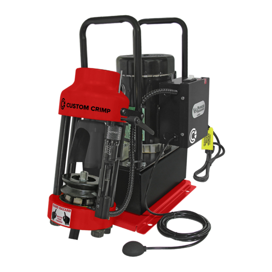
Innovating SMART Hose Assembly Solutions Since 1979 D105M COMPONENT PARTS & TECHNICAL DATA 1HP/110V/Single Phase pump for fast crimps Powerful 35 Ton Hydraulic Cylinder Adjustable Retraction Stop Optional Flexible 24" Work Lamp Main Power Switch Electrical Enclosure Removable Pusher CustomCrimp QR Code ®... -
Page 5: Features
Innovating SMART Hose Assembly Solutions Since 1979 D105M FEATURES Metric Micrometer “Micro-Crimp Open design, two piece “slide Built-in adjustable retraction Adjuster” is fully adjustable to in” die set and removable stop limits ram retraction for make precise and repeatable pusher allows the operator to quick repetitive crimps. -
Page 6: Initial Set
Innovating SMART Hose Assembly Solutions Since 1979 INITIAL SET UP FOLLOW THESE STEPS BEFORE YOU USE THE CRIMPER FOR THE FIRST TIME. • Mount the crimper on a sturdy workbench in a well-lit area. Workbench should be able to support the crimper and components weight. Note: The D105 series can be mounted on the D-Series Drawer/Stand and bolted onto the workbench. -
Page 7: Lubrication Procedure
Innovating SMART Hose Assembly Solutions Since 1979 LUBRICATION PROCEDURE Grease Point # 1 Insert the pressure plate into the bottom flange of the crimper, making sure that it is seated squarely into the bottom flange. Place a thin layer of CrimpX oil (supplied with crimper) or a high Photo # 1 pressure molybdenum high pressure grease on the surface the dies sit on (as shown in photo # 1). -
Page 8: Crimping Procedure
Innovating SMART Hose Assembly Solutions Since 1979 CRIMPING PROCEDURE Note: Follow the lubrication procedure prior to crimping procedure. NOTE: FAILURE TO LUBRICATE THE DIE SET AND COMPRESSION RING COULD RESULT IN THE DIE SET SEIZING IN THE BASE FLANGE. Step 1: Insert the pressure plate into the bottom flange of the crimper, making sure that it is seated squarely into the bottom flange. - Page 9 Innovating SMART Hose Assembly Solutions Since 1979 CRIMPING PROCEDURE Step 4: Place the lubricated die set squarely in the pressure plate. Step 5: Align the fitting in the die set according to the hose and fitting manufacturer’s recommendation. Step 6: Place the lubricated compression ring over the die set and compress the die set by hand to hold the hose and fitting in place.
- Page 10 Innovating SMART Hose Assembly Solutions Since 1979 CRIMPING PROCEDURE Note: Make sure the compression ring is seated evenly on the die set. CAUTION: The notches on the die set must be completely covered by the compression ring prior to starting the crimp. •...
- Page 11 Innovating SMART Hose Assembly Solutions Since 1979 CRIMPING PROCEDURE Step 7: Slide the Pusher onto the pusher retaining ring on the hydraulic cylinder. Note: Make sure slot in pusher goes over lip on pusher retaining ring. CAUTION: Damage to pusher and retaining ring can occur if misaligned. Front View Pusher Rear View...
- Page 12 Innovating SMART Hose Assembly Solutions Since 1979 CRIMPING PROCEDURE Step 8: Set the Micro-Crimp Adjuster to the setting recommended by the hose and fitting manufacturer for the combination of hose and fitting being crimped. NOTE: The Metric Micro-Crimp Adjuster is a direct reading micrometer.
-
Page 13: Calibration Check Procedure
Innovating SMART Hose Assembly Solutions Since 1979 CALIBRATION CHECK PROCEDURE THE CRIMPER IS CALIBRATED PRIOR TO SHIPMENT, BUT A CALIBRATION CHECK IS RECOMMENDED PRIOR TO USING THE CRIMPER FOR THE FIRST TIME. Note: Follow the lubrication procedure prior to calibration check. NOTE: FAILURE TO LUBRICATE THE DIE SET AND COMPRESSION RING COULD RESULT IN THE DIE SET SEIZING IN THE BASE FLANGE. - Page 14 Innovating SMART Hose Assembly Solutions Since 1979 CALIBRATION CHECK PROCEDURE Step 5: Set the Metric Micro-Crimp Adjuster at “0”. Note: Set the Micro-Crimp Adjuster at “100” for the Standard Micrometer. Set the Micro-Crimp Adjuster at “95” for the DC Micrometer. Step 6: Depress and hold the Start/Stop switch, until the Die set is completely closed and oil pressure has built up in the hydraulic cylinder.
-
Page 15: D105 / D165 D-Series Drawer Assembly / Stand (Instructions)
Innovating SMART Hose Assembly Solutions Since 1979 D105/D165 D-SERIES DRAWER ASSEMBLY / STAND Note: This instructions can be used for D105/D165/D165-T420 series crimpers. Install (2) 3/8-16 x 1" carriage bolts in front two holes (as shown in picture # 1). Use 3/8" plastic retaining washer to hold bolt into place. -
Page 16: Included Accessories
Innovating SMART Hose Assembly Solutions Since 1979 INCLUDED ACCESSORIES Metric Micrometer D100/D105 Pusher w/ D100/D105 Compression Ring D100/D105 Pressure Plate P/N:101587 Magnets P/N:100813-01 P/N:100849 P/N:100869 Pneumatic Pendent Switch D165 Coupling Stop CRIMPX Die Lubricant Oil: Vent Plug (Included) P/N:101349 P/N:100954 4 oz bottle with dauber cap P/N:9847K13 P/N:103886... -
Page 17: Available Accessories
Innovating SMART Hose Assembly Solutions Since 1979 AVAILABLE ACCESSORIES Standard Micrometer DC Micrometer D100/D105 Notched Flexible 24" Work Lamp P/N:100628 P/N:101489 Compression Ring P/N:1668-02 P/N:101190 Die Storage Shelf D-Series Drawer Assembly/Stand Die Removal Magnet CRIMPX Die Lubricant: P/N:101431 P/N:104650 P/N:104679 Grease 4 oz can with brush P/N:104162 D100 Series Die Rings... -
Page 18: Troubleshooting
Innovating SMART Hose Assembly Solutions Since 1979 TROUBLESHOOTING PROBLEM: CRIMPER WILL NOT RUN AT ALL • The power switch (white rocker switch) is also a circuit breaker. Make certain that this circuit breaker has not tripped. • Check the wall outlet. The crimper comes from the factory wired for a 110 volt circuit. Use of exten- sion cords or outlets with inadequate power can damage the motor or crimper controls. -
Page 19: Component Parts Breakdown
Innovating SMART Hose Assembly Solutions Since 1979 COMPONENT PARTS BREAKDOWN D100 SERIES DIE PARTS (AI-100724) ITEM PART NUMBER DESCRIPTION 101065-COLOR DIE RING HALF D100 SERIES D100 SERIES DIE PARTS (AI-100724) VARIES WITH THE DIE SIZE 8 PC DIE FINGER SET ITEM PART NUMBER DESCRIPTION... - Page 20 Innovating SMART Hose Assembly Solutions Since 1979 COMPONENT PARTS BREAKDOWN D105 Crimper Assembly (101428) ITEM PART NUMBER DESCRIPTION 101430 D-105 Base Plate 101633 Pump Assembly 90126A029 1/4 Flat Washer 91102A029 1/4 Lock Washer 92865A540 1/4-20 x 3/4 Hex Bolt 101433 D105 Handle 101433-Slotted D105 Slotted Handle...
- Page 21 Innovating SMART Hose Assembly Solutions Since 1979 COMPONENT PARTS BREAKDOWN D105 Head Assembly (101480) ITEM PART NUMBER DESCRIPTION 101209 Head Sub-Assembly 101788 Micrometer Mount Assembly 100812 Pusher Retaining Pin 91253A624 3/8-16 x 1 FHCS 101092 Limit Switch Bracket 903 Switch Limit Switch 100692 Limit Switch Guard...
- Page 22 Innovating SMART Hose Assembly Solutions Since 1979 COMPONENT PARTS BREAKDOWN 35-Ton Head Sub-Assembly (101209) ITEM PART NUMBER DESCRIPTION 103122 35-Ton Cylinder/Flange 100329 Strain Rod - 8 1/2" 100325 Bottom Flange 750SPCL 3/4 Flat Washer - Special 95462A538 3/4-10 Hex Nut...
- Page 23 Innovating SMART Hose Assembly Solutions Since 1979 COMPONENT PARTS BREAKDOWN D105 Micrometer Mount Assembly (101788) Item Part Number Description 100898-01 Micrometer Arm 100898-02 Micrometer Base 100898-03 Micrometer Suspension Flange 91253A189 8-32 x 1/4 HSFHS...
- Page 24 Innovating SMART Hose Assembly Solutions Since 1979 COMPONENT PARTS BREAKDOWN 35 Ton Cylinder / Flange Assembly (103122) ITEM PART NUMBER DESCRIPTION 102511 Cylinder Body 101515 Cylinder Piston 030D90 030 Disogrin O-Ring 100689 Cylinder Piston Cap 91251A539 1/4-20 X 5/8 SHCS 101282 Cylinder Spring 101516...
-
Page 25: Customcrimp® "No-Nonsense" Warranty Statement
318 North Co. Rd 400 East Valparaiso IN 46383 If any product or part manufactured by Custom Crimp® is found to be defective by Custom Crimp®, at its option, Custom Crimp® will either repair or replace the defective part or product and return via ground transportation, freight prepaid. -
Page 26: Custom Crimp® Contact Information
Innovating SMART Hose Assembly Solutions Since 1979 CUSTOM CRIMP®, YOUR SINGLE SOURCE FOR HOSE ASSEMBLY PRODUCTS. CUSTOM CRIMP® | Custom Machining Services, Inc. 326 North 400 East Valparaiso, IN 46383 Visit us at: www.customcrimp.com For sales: ccsales@customcrimp.us For support: ccsupport@customcrimp.us...
Need help?
Do you have a question about the D105M Series and is the answer not in the manual?
Questions and answers