
Related Manuals for Custom Crimp D165M Series


Summary of Contents for Custom Crimp D165M Series
- Page 1 Innovating SMART Hose Assembly Solutions Since 1979 D165M SERIES HYDRAULIC CRIMPERS OPERATORS MANUAL...
-
Page 2: Safety Precautions
Innovating SMART Hose Assembly Solutions Since 1979 SAFETY PRECAUTIONS • READ INSTRUCTIONS AND IDENTIFY ALL COMPONENT PARTS BEFORE USING CRIMPER. • D165 SERIES CRIMPERS CAN PRODUCE 62 TONS OF CRIMPING FORCE. • KEEP BOTH HANDS AWAY FROM PINCH POINTS. • CONSULT HOSE AND FITTING MANUFACTURER FOR CORRECT MACHINE SETTINGS AND CRIMP MEASUREMENTS. -
Page 3: Table Of Contents
CRIMPING WITH STANDARD COMPRESSION RING-----------------------------------------------------------------------------10 CRIMPING WITH NOTCHED COMPRESSION RING-----------------------------------------------------------------------------15 CALIBRATION CHECK PROCEDURE---------------------------------------------------------------------------------------------19 D105 / D165 D-SERIES DRAWER ASSEMBLY / STAND (INSTRUCTIONS)------------------------------------------------------22 INCLUDED ACCESSORIES----------------------------------------------------------------------------------------23 AVAILABLE ACCESSORIES----------------------------------------------------------------------------------------24 TROUBLESHOOTING---------------------------------------------------------------------------------------------------------25 COMPONENT PARTS BREAKDOWN--------------------------------------------------------------------------------------------26 ® CUSTOM CRIMP “NO-NONSENSE” WARRANTY STATEMENT---------------------------------------------------------------31 ® CUSTOM CRIMP CONTACT INFORMATION--------------------------------------------------------------------------------------32... -
Page 4: Component Parts & Technical Data
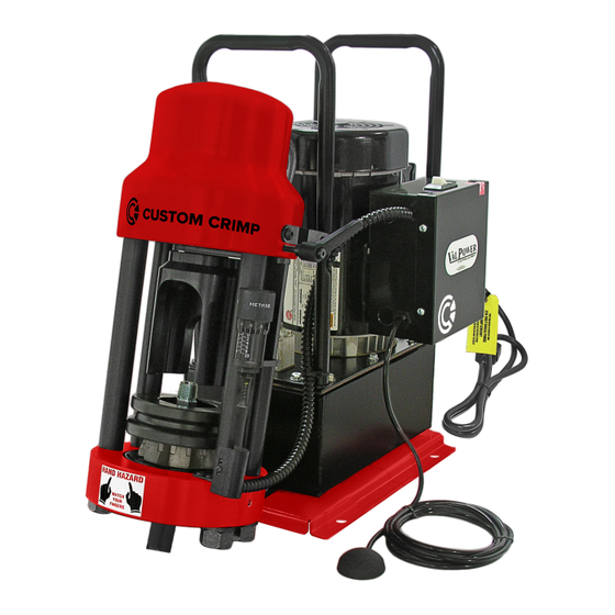
Innovating SMART Hose Assembly Solutions Since 1979 COMPONENT PARTS & TECHNICAL DATA 1HP/110V/Single Phase pump for fast crimps Powerful 62 Ton Hydraulic Cylinder Adjustable Retraction Stop Optional Flexible 24" Work Lamp Main Power Switch Electrical Enclosure Removable Pusher Micrometer Style Adjustment 1 Gallon Reservoir Calibration Adjustment Screw Pneumatic Switch... -
Page 5: Available D105 / D165 D-Series Drawer Assembly / Stand
Innovating SMART Hose Assembly Solutions Since 1979 D105/D165 D-SERIES DRAWER ASSEMBLY / STAND D165 Series Crimper The crimper bolts directly on top of the mounting holes of the D-Series Drawer Base mounting holes allow the drawer to be bench or truck bed mounted if required Die storage drawer to keep frequently used die sets and... -
Page 6: Features
Innovating SMART Hose Assembly Solutions Since 1979 FEATURES Metric Micrometer “Micro-Crimp Open design, two piece “slide Built-in adjustable retraction Adjuster” is fully adjustable to in” die set and removable stop limits ram retraction for make precise and repeatable pusher allows the operator to quick repetitive crimps. -
Page 7: Initial Set
Innovating SMART Hose Assembly Solutions Since 1979 INITIAL SET UP FOLLOW THESE STEPS BEFORE YOU USE THE CRIMPER FOR THE FIRST TIME. • Mount the crimper on a sturdy workbench in a well-lit area. Workbench should be able to support the crimper and components weight. Note: The D165 series can be mounted on the D-Series Drawer/Stand and bolted onto the workbench. - Page 8 Innovating SMART Hose Assembly Solutions Since 1979 INITIAL SET UP • Check electrical circuit to be certain that it matches the crimper requirements shown on the voltage tag attached to the crimper cord. • Plug the D165 crimper directly into a 110 volt, 15 amp wall outlet. Note: The optional 220 volts / 2HP unit must be connected to a 220 volts 20 amp wall outlet.
-
Page 9: Lubrication Procedure
Innovating SMART Hose Assembly Solutions Since 1979 LUBRICATION PROCEDURE Grease Point # 1 Insert the pressure plate into the bottom flange of the crimper, making sure that it is seated squarely into the bottom flange. Place a thin layer of CrimpX oil (supplied with crimper) or a high Photo # 1 pressure molybdenum high pressure grease on the surface the dies sit on (as shown in photo # 1). -
Page 10: Crimping With Standard Compression Ring
Innovating SMART Hose Assembly Solutions Since 1979 CRIMPING WITH STANDARD COMPRESSION RING Note: Follow the lubrication procedure prior to crimping procedure. NOTE: FAILURE TO LUBRICATE THE DIE SET AND COMPRESSION RING COULD RESULT IN THE DIE SET SEIZING IN THE BASE FLANGE. Step 1: Insert the pressure plate into the bottom flange of the crimper, making sure that it is seated squarely into the bottom flange. - Page 11 Innovating SMART Hose Assembly Solutions Since 1979 CRIMPING WITH STANDARD COMPRESSION RING Step 4: Place the Lubricated Die Set squarely in the pressure plate. Step 5: Align the Fitting in the die set according to the hose and fitting manufacturer’s recommendation. Step 6: Place the Lubricated Compression Ring over the die set and compress the die set by hand to hold the hose and fitting in place.
- Page 12 Innovating SMART Hose Assembly Solutions Since 1979 CRIMPING WITH STANDARD COMPRESSION RING Note: Make sure the compression ring is seated evenly on the die set. CAUTION: The notches on the die set must be completely covered by the compression ring prior to starting the crimp.
- Page 13 Innovating SMART Hose Assembly Solutions Since 1979 CRIMPING WITH STANDARD COMPRESSION RING Step 7: Slide the Pusher onto the pusher retaining ring on the hydraulic cylinder. Note: Make sure slot in pusher goes over lip on pusher retaining ring. CAUTION: Damage to pusher and retaining ring can occur if misaligned.
- Page 14 Innovating SMART Hose Assembly Solutions Since 1979 CRIMPING WITH STANDARD COMPRESSION RING Step 8: Set the Micro-Crimp Adjuster to the setting recommended by the hose and fitting manufacturer for the combination of hose and fitting being crimped. NOTE: The Metric Micro-Crimp Adjuster is a direct reading micrometer.
-
Page 15: Crimping With Notched Compression Ring
Innovating SMART Hose Assembly Solutions Since 1979 CRIMPING WITH NOTCHED COMPRESSION RING WHEN USING THE NOTCHED COMPRESSION RING, FOR USE WITH 90 DEGREE FITTING ONLY, FOLLOW THESE PROCEDURES: Note: Follow the lubrication procedure prior to crimping procedure. CAUTION: Failure to lubricate the die set and notched compression ring could result in the die seizing in the base flange. - Page 16 Innovating SMART Hose Assembly Solutions Since 1979 CRIMPING WITH NOTCHED COMPRESSION RING CAUTION: DO NOT MISALIGN NOTCHED Step 7: COMPRESSION RING OR DAMAGE WILL OCCUR. Note: When crimping with the notched compression ring the “Notched” MUST face forward or damage can occur to die fingers if parts aren’t aligned properly.
- Page 17 Innovating SMART Hose Assembly Solutions Since 1979 CRIMPING WITH NOTCHED COMPRESSION RING Step 8: Slide the Pusher onto the pusher retaining ring on the hydraulic cylinder. Note: Make sure slot in pusher goes over lip on pusher retaining ring. Refer to page 13 for details if needed. CAUTION: Damage to pusher and retaining ring can occur if misaligned.
- Page 18 Innovating SMART Hose Assembly Solutions Since 1979 CRIMPING WITH NOTCHED COMPRESSION RING Step 10: Check the final crimp diameter with calipers to confirm that it is within manufacturer’s specifications. Note: Always consult with your hose and fitting manufacturer to obtain the must current crimp specifications.
-
Page 19: Calibration Check Procedure
Innovating SMART Hose Assembly Solutions Since 1979 CALIBRATION CHECK PROCEDURE THE CRIMPER IS CALIBRATED PRIOR TO SHIPMENT, BUT A CALIBRATION CHECK IS RECOMMENDED PRIOR TO USING THE CRIMPER FOR THE FIRST TIME. Note: Follow the lubrication procedure prior to calibration check. NOTE: FAILURE TO LUBRICATE THE DIE SET AND COMPRESSION RING COULD RESULT IN THE DIE SET SEIZING IN THE BASE FLANGE. - Page 20 Innovating SMART Hose Assembly Solutions Since 1979 CALIBRATION CHECK PROCEDURE Step 4: Slide the Pusher onto the pusher retaining ring on the hydraulic cylinder. Note: Make sure slot in pusher goes over lip on pusher retaining ring. Refer to page 13 for details if needed. CAUTION: Damage to pusher and retaining ring can occur if misaligned.
- Page 21 Innovating SMART Hose Assembly Solutions Since 1979 CALIBRATION CHECK PROCEDURE Step 7: If the above conditions are not met, the crimper requires recalibration, hold the micrometer barrel with a 5/16 inch open end wrench and rotate the stem either in or out with a 5/32 inch hex key wrench. Note: 1/4 turn of screw will change crimp diameter approximately 0.008".
-
Page 22: D105 / D165 D-Series Drawer Assembly / Stand (Instructions)
Innovating SMART Hose Assembly Solutions Since 1979 D105/D165 D-SERIES DRAWER ASSEMBLY / STAND Install (2) 3/8-16 x 1" carriage bolts in front two holes (as shown in picture # 1). Use 3/8" plastic retaining washer to hold bolt into place. Slide the drawer slightly out to access two rear holes (as shown in picture # 2). -
Page 23: Included Accessories
Innovating SMART Hose Assembly Solutions Since 1979 INCLUDED ACCESSORIES Metric Micrometer Pusher w/ Magnets Compression Ring Pressure Plate P/N:101587 P/N:100825-01 P/N:102213 P/N:102211 Pneumatic Pendent Switch D165 Coupling Stop CRIMPX Die Lubricant Oil: Vent Plug P/N:101349 P/N:100954 4 oz bottle with dauber cap P/N:9847K13 P/N:103886 (5) D100 Screws... -
Page 24: Available Accessories
Innovating SMART Hose Assembly Solutions Since 1979 AVAILABLE ACCESSORIES Standard Micrometer DC Micrometer Notched Compression Ring Flexible 24" Work Lamp P/N:100628 P/N:101489 (Ideal for 90 deg. Fittings) P/N:1668-02 P/N:103072 Die Storage Shelf D-Series Drawer Die Removal Magnet CRIMPX Die Lubricant: P/N:101431 Assembly/Stand P/N:104679... -
Page 25: Troubleshooting
Innovating SMART Hose Assembly Solutions Since 1979 TROUBLESHOOTING PROBLEM: CRIMPER WILL NOT RUN AT ALL • The white rocker switch is also a circuit breaker. Check to see that the circuit breaker has not been tripped. • Check the wall outlet. The crimper comes from the factory wired for a 115 volt single phase circuit. Use of extension cords or outlets with inadequate power can damage the motor. -
Page 26: Component Parts Breakdown
Innovating SMART Hose Assembly Solutions Since 1979 COMPONENT PARTS BREAKDOWN D100 SERIES DIE PARTS (AI-100724) ITEM PART NUMBER DESCRIPTION 101065-COLOR DIE RING HALF D100 SERIES D100 SERIES DIE PARTS (AI-100724) VARIES WITH THE DIE SIZE 8 PC DIE FINGER SET ITEM PART NUMBER DESCRIPTION... - Page 27 Innovating SMART Hose Assembly Solutions Since 1979 COMPONENT PARTS BREAKDOWN 60 Ton Cylinder / Top Flange Assembly (102219) Item Part Number Description 102158 60 Ton Body / Top Flange 100651 60 Ton Piston 227-9250 227 Disogrin O-Ring 101106 Piston End Cap 100760_12 60 Ton Spring 102287...
- Page 28 Innovating SMART Hose Assembly Solutions Since 1979 COMPONENT PARTS BREAKDOWN D165 Crimper Head Assembly (102 Item Part Number Descrip 102219 60 Ton Cylinder 102212 Strain 102159 Bottom F 11038 7/8 Narrow R 90499A845 7/8 - 14 H 102224 Retraction S KHA-126 Stop Rod Lock 102220...
- Page 29 Innovating SMART Hose Assembly Solutions Since 1979 COMPONENT PARTS BREAKDOWN D165 Crimper Assembly (102221) Item Part Number Description 101430 D165 Base Plate 101633 Pump Assembly 92865A540 1/4-20 x 3/4 HHCS 91102A029 1/4 Lock Washer 90126A029 1/4 Flat Washer 102161 D165 Crimper Head Assembly 101429 Crimper Head Mounting Bracket 92865A626...
- Page 30 Innovating SMART Hose Assembly Solutions Since 1979 COMPONENT PARTS BREAKDOWN D165 Micrometer Mount Assembly (102220) Item Part Number Description 102214 Micrometer Suspension Flange 102217 Micrometer Brace 102215 Micrometer Base Bracket 91253A194 8-32 x 1/2 HSFHCS 98296A245 3/16 Dia. x 1/2 Spring Pin...
-
Page 31: Customcrimp® "No-Nonsense" Warranty Statement
318 North Co. Rd 400 East Valparaiso IN 46383 If any product or part manufactured by Custom Crimp® is found to be defective by Custom Crimp®, at its option, Custom Crimp® will either repair or replace the defective part or product and return via ground transportation, freight prepaid. -
Page 32: Custom Crimp ® Contact Information
Innovating SMART Hose Assembly Solutions Since 1979 CUSTOM CRIMP®, YOUR SINGLE SOURCE FOR HOSE ASSEMBLY PRODUCTS. CUSTOM CRIMP® | Custom Machining Services, Inc. 326 North 400 East Valparaiso, IN 46383 Visit us at: www.customcrimp.com For sales: ccsales@customcrimp.us For support: ccsupport@customcrimp.us...
Need help?
Do you have a question about the D165M Series and is the answer not in the manual?
Questions and answers