Advertisement
Quick Links
Advertisement

Related Manuals for Custom Crimp CC1000


Summary of Contents for Custom Crimp CC1000
- Page 1 CC1000 CRIMPER OPERATORS MANUAL WITH ACT CONTROLLER...
- Page 2 DIE SET UP AND INSTALLATION --------------------------------------------------------------------13 INITIAL SET UP AND MAINTENANCE --------------------------------------------------------------14 TROUBLESHOOTING ------------------------------------------------------------------------------------15 EXPLODED PARTS BREAKDOWN ------------------------------------------------------------------------16 For Parts and Service, Contact: Custom Machining Services, Inc. Valparaiso, In 46383 (219) 462-6128 CC1000 Crimper Operators Manual With ACT™ Controller (Revised 03/28/2016)
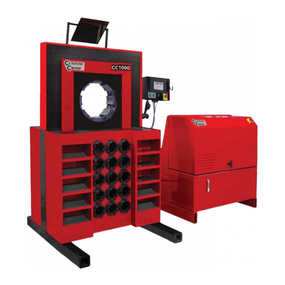
- Page 3 COMPONENT PART IDENTIFICATION 230mm to 145mm Adapter Die Adjustable Mirror 145mm to 99mm Master Die Adapter Die Hydraulic Die Power Switch Industrial Die Hydraulic 99mm Die Storage Shelves Storage Pockets Hydraulic Power Unit and Controls Oil Level Sight Glass 230mm to 145mm Adapter Dies 145mm to 99mm Adapter Dies...
- Page 4 CRIMPER SPECIFICATIONS AND INITIAL SET UP SPECIFICATIONS: MAX HEAD OPENING W/O DIES ------------------------------------------------------------------------350 MM (13.7 IN) MASTER DIE INSIDE DIAMETER -------------------------------------------------------------------------230 MM (9.1 IN) MAXIMUM DIE OPENING ----------------------------------------------------------DIE CLOSED DIAMETER + 125 MM CRIMPER SIZE -----------------------------------------------------------------44 IN WIDE X 30 IN DEEP X 74 IN HIGH WEIGHT ------------------------------------------------------------------------------------------------------6185 LB.
- Page 5 AccuCrimp ACT CONTROL PANEL U.S. Patent No: 7,383,709 TOUCH SCREEN CONTROL PANEL EMERGENCY STOP MANUAL MODE FUNCTION: CLOSE DIES AUTO MODE FUNCTION: CYCLE START MANUAL MODE FUNCTION: OPEN DIES AUTO MODE FUNCTION: CYCLE STOP NOTE: MANUAL MODE IF THE CRIMPER IS IN , THE GREEN OPEN/CLOSE BUTTONS WILL OPEN AND CLOSE THE CRIMPER HEAD.
- Page 6 CONTROLLER QUICK START While the ACT crimper has the ability to perform a number of fully automatic functions, manual operation is also possible. To make a manual crimp, two numbers are needed: • The closed diameter of the die (in either in or mm) •...
- Page 7 HOW TO MAKE MINOR CORRECTIONS Due to variations in hose and fi tting tolerances a minor crimp adjustment may be required if the measured diameter of the fi nal crimp is not within the hose and fi tting manufacturer’s specifi cations. technology makes minor corrections a simple process which requires no addition or subtraction.
- Page 8 HOW TO ADD A SAVED DIE Up to 50 different dies can be saved in the computer memory. These dies can be recalled in the set up process eliminating the need to re- enter the die size each time. To enter a saved die: From the OPTION screen, press SETUP MODE.
- Page 9 HOW TO ADD A SAVED CRIMP • Adjust the die diameter and crimp diameter as required and place the crimper in MANUAL mode. Press SAVE. • Select a location (1-150) and press EDIT. • • Enter a description (up to 12 characters). Press SAVE and EXIT.
- Page 10 FULL AUTO MODE With the crimper in FULL AUTO mode additional functions are available: The crimper will cycle automatically from the CRIMP button on • the touch screen, the green CYCLE START button on the panel, or the foot switch. •...
- Page 11 ADJUST CRIMP COUNT If a production operation is interrupted for some reason, it is possible to reset the counter to where the operation was at the point of interruption. • Press the Adjust Count button from the auto crimp screen. •...
- Page 12 ADDITIONAL FEATURES Pre-Loaded Crimp Specifi cations In addition to the ability to store up to 50 user entered dies and 100 user entered crimp settings, the Controller has the capability of accepting pre loaded manufacturer’s crimp specifi cations. Custom Crimp does not maintain these specifi...
- Page 13 INDUSTRIAL CRIMP CALCULATOR The Industrial Hose Crimp Calculator is part of the ACT controller package on many Custom Crimp crimpers capable ® of crimping industrial hoses. With a few simple measure- ments, it takes the guess work out of industrial hose crimping and eliminates the need for charts and graphs.
- Page 14 Press the CHANGE DIES button on the controller to easily open and close the master dies without aff ecting crimper settings Note that on the CC1000, the master dies must be slightly closed in order to completely insert the die removal tool.
- Page 15 INITIAL SET UP AND PLC RESET Initial Setup Check to be certain that the motor rotates in the direction of the arrow shown on the motor housing. If motor rotation is opposite of the direction of the arrow, reverse any two hot wires in the electrical plug. Damage to the pump can result if the motor does not rotate in the correct direction.
- Page 16 TROUBLESHOOTING PROBLEM: CRIMPER WILL NOT RUN AT ALL • Check the E-Stop switch to be certain that it is not depressed. A slight twist is required to release switch after it has been depressed. • PLC (Programmable Logic Control) must be reset. See instructions on the previous page. PROBLEM: CRIMPER RUNS BUT IS SLOW OR NON-FUNCTIONAL •...
- Page 17 EXPLODED PARTS VIEW CC1000 SHEET METAL ASSEMBLY ITEM PART NUMBER DESCRIPTION 103204-1 CC1000 FRONT PANEL 103209 CC1000 PROTECTIVE SLIDE PLATE 103214 CC1000 BACK PANEL 103236 CC1000 PROTECTIVE PLATE WRAP 103219 CC1000 TOP FRAME WRAP 91239A318 M6 X 12 BHCS 91239A321...
- Page 18 CC 1000 STATIONARY WEAR PLATE 91294A242 M6 X 25 FHCS 103158 CC 1000 CYLINDER ASSEMBLY 91290A837 M16 X 70 SHCS 103206-L CC1000 LEFT SUPPORT LEG ASMB. 103206-R CC1000 RIGHT SUPPORT LEG ASMB. 91290A626 M12 X 50 SHCS 91166A290 M12 WASHER...
- Page 19 EXPLODED PARTS VIEW CC1000 PROTECTIVE PLATES AND GUIDES ASSEMBLY ITEM PART NUMBER DESCRIPTION 103146 CC1000 FRAME 103193 CC 1000 SIDE GUIDE PLATE 91290A620 M12 X 35 SHCS 91290A432 M8 X 25 SHCS 103196 CC 1000 MASTER DIE COVER PLATE 91294A284...
- Page 20 EXPLODED PARTS VIEW CC1000 MASTER DIE ASSEMBLY ITEM PART NUMBER DESCRIPTION 103147 CC1000 MASTER DIE CARRIER 103249 CC1000 MASTER DIE ALIGNMENT NUT 91290A144 M4 X 10 SHCS 91290A446 M8 X 45 SHCS 103156 CC1000 MASTER DIE SHOE 103470 DIE SPRING...
- Page 21 EXPLODED PARTS VIEW CC1000 MIRROR BRACKET ASSEMBLY (103161-3) ITEM PART NUMBER DESCRIPTION 103219 CC1000 SHEET METAL WRAP 103307 CC600/1000 MIRROR BRACKET SUPPORT ARMS 103345 CC600/1000 MIRROR ATTACHMENT BRACKET 103471 12" X 12" MIRROR 91239A620 M12 X 40 BHCS 91255A624 3/8-16 X 1 BHCS...
- Page 22 EXPLODED PARTS VIEW CC600/1000 TOWER ASSEMBLY ITEM PART NUMBER DESCRIPTION 7309K342 CC600/1000 TOWER BOX 103308-1 CC600/1000 TOWER SWIVEL BRACKET 103308-2 CC600/1000 TOWER SUPPORT ARM 103308-3 CC600/1000 TOWER MOUNTING BRACKET 91255A242 10-24 X 1/2" BHCS 91255A540 1/4 - 20 x 3/4" BHCS KHA-150 1/2-13 LOCKING HANDLE KHA-108...
- Page 23 326 North Co. Rd 400 East Valparaiso IN 46383 If any product or part manufactured by Custom Crimp is found to be defective by Custom Crimp, at its option, Custom Crimp will either repair or replace the defective part or product and return via ground transportation, freight prepaid.
- Page 24 Custom Crimp ® Custom Machining Services, Inc. 326 N. County Rd. 400 East Valparaiso, IN 46383 Ph: (219) 462-6128 Fax: (219) 464-2773 www.customcrimp.com See the complete line of CustomCrimp ® Crimpers and Accessories at: CustomCrimp www.customcrimp.com (219) 462-6128 ®...
Need help?
Do you have a question about the CC1000 and is the answer not in the manual?
Questions and answers