Delta FOUL V3 Installation Manual
Hide thumbs
Also See for FOUL V3:
- Installation and operating manual (56 pages) ,
- Installation and operating manual (32 pages)

Related Manuals for Delta FOUL V3


Summary of Contents for Delta FOUL V3
- Page 1 DELTA FOUL V3 INSTALLATION GUIDE W W W.D ELTAM E MBRAN ES . CO M W W W.D ELTAM E MBRAN ES . CO M W W W.D ELTAM E MBRAN ES . CO M W W W.D ELTAM E MBRAN ES . CO M...
- Page 2 Regular servicing of sump pumps will increase efficiency and extend the life of the pump. All Delta Membrane pump systems can be maintained and serviced by our recommended service companies or installing contractor.
-
Page 3: Table Of Contents
Contents Foul V3 Overview OVERVIEW TECHNICAL INFORMATION CHAMBER OVERVIEW PARTS INCLUDED OPTIONAL EXTRAS Discharge Pipework & Fittings DISCHARGE PIPEWORK & FITTINGS SPARE PARTS Pump Chamber Depth Limits PUMP CHAMBER DEPTH LIMITS Installation Guidelines INSTALLATION GUIDELINES PUMP STATION LOCATIONS RC BOX DIMENSIONS... -
Page 4: Foul V3 Overview
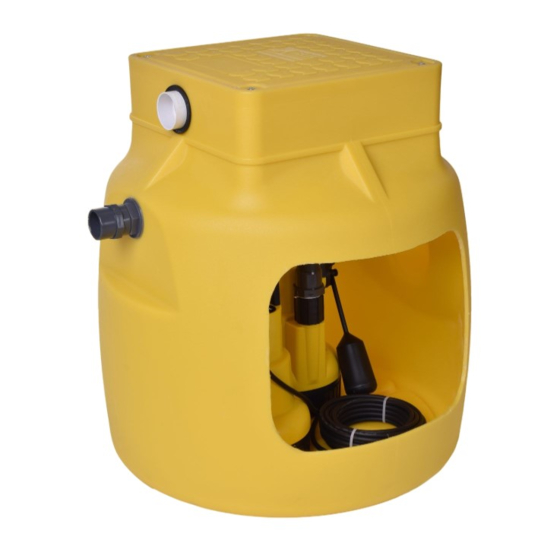
1. Delta Foul V3 Overview 1.0 FOUL V3 OVERVIEW The Delta Foul V3 is a packaged pump station designed to The pump station is delivered as a complete package collect foul water. Typically, the Foul V3 would be used to including all internal pipework and a D10SA foul vortex pump. -
Page 5: Chamber Overview
1. Delta Foul V3 Overview 1.2 CHAMBER OVERVIEW Delta Foul V3 Part Description Foul V3 Chamber Chamber Overview Screed Cable Duct Insulation Discharge Pipe MS20 Distribution Board Foul V3 Chamber Part Description Basement Slab Non-switched Fused Spur Screed Cable Duct... -
Page 6: Discharge Pipework & Fittings
2.0 DISCHARGE PIPEWORK & FITTINGS A selection of discharge pipework and fittings are available for the Foul V3 pump station. Should you require to place an order for any of these items, please complete the form below, scan and email to pumps@deltamembranes.com to allow us to process your order. -
Page 7: Spare Parts
Part No. 2” Male Iron (Non-pressure) DMS-335 2” Female - 2” Male Adaptor DMS-337 2” Non Return Valve DMS-327 Foul V3 Discharge Bend DMS-334 D10SA Pump DMS-120 Discharge Arm c/w DC65 Connector DMS-129 01992 523 523 | info@deltamembranes.com | www.deltamembranes.com... -
Page 8: Pump Chamber Depth Limits
3. Pump Chamber Depth Limits If the inlet does not allow the pump chamber to be within depth limits, please contact Delta Technical on 01992 523 523 or pumps@deltamembranes.com to discuss chamber options. < 500mm The pump chamber must be installed no more than 500mm below floor finishes. -
Page 9: Installation Guidelines
4. Installation Guidelines 4.0 INSTALLATION GUIDELINES The following instructions are for guidance only and it is the contractors responsibility to ensure that the installation is in accordance with the prevailing ground conditions and good building practice, to eliminate any potential damage to the pump station either during or after installation. Please read these instructions carefully prior to installing the chamber. -
Page 10: Installation Of Chamber
Install re-bar as per structural engineer’s 10.0 for RC box internal dimensions. drawings. Lay inlet and discharge pipework. Allow Pour concrete to form RC box as per pipework to protrude into RC box by a structural engineer’s drawings. minimum of 100mm. FOUL V3 INSTALLATION GUIDE... -
Page 11: Installation Of Chamber - Section B
5. Installation of Chamber 5.1 INSTALLATION OF CHAMBER - SECTION B Connecting 110mm inlet pipework Saw off socket end/s, where inlet pipe/s are Position chamber in RC box. to be connected. Fit push fit coupler. Connect inlet pipework to the required chamber spigot. -
Page 12: Installation Of Chamber - Section C
FOUL V3 INSTALLATION GUIDE... - Page 13 5. Installation of Chamber Connecting discharge and cable duct Ensure a draw cord is pulled through the cable duct as the cable duct is built. 01992 523 523 | info@deltamembranes.com | www.deltamembranes.com...
-
Page 14: Installation Of Chamber - Section D1
To be followed when installing chamber in an RC box. Check all pipes are connected to the Completely fill chamber with water. chamber correctly. Fill void between RC box and chamber with concrete (min. C35 grade) or as per engineer’s drawings. FOUL V3 INSTALLATION GUIDE... -
Page 15: Installation Of Chamber - Section D2
5. Installation of Chamber 5.4 INSTALLATION OF CHAMBER - SECTION D2 Backfill around chamber with concrete To be followed when installing chamber in the ground. Completely fill chamber with water. Fill void between soil and chamber with concrete (min. C35 grade) or as per engineer’s drawings. -
Page 16: Installation Of Chamber - Section D3
To be followed when installing chamber in the ground with a reinforced cage. Completely fill chamber with water. Fill void between soil and chamber with concrete (min. C35 grade) or as per engineer’s drawings. Allow concrete to cure. FOUL V3 INSTALLATION GUIDE... -
Page 17: Installation Of Chamber - Section E
5. Installation of Chamber 5.6 INSTALLATION OF CHAMBER - SECTION E Preparing chamber for installation of pump Pump out water from chamber. Manually remove any debris from chamber and residual water using a wet vacuum. 01992 523 523 | info@deltamembranes.com | www.deltamembranes.com... -
Page 18: Installation Of Chamber - Section F
5.7 INSTALLATION OF CHAMBER - SECTION F(REINFORCED CAGE) Fitting discharge to pump Wrap the thread on the nipple glued in to the Hand tighten the discharge arm into the 90˚ bend with PTFE tape. pump discharge outlet. FOUL V3 INSTALLATION GUIDE... -
Page 19: Installation Of Chamber - Section G
5. Installation of Chamber 5.8 INSTALLATION OF CHAMBER - SECTION G Installing pump in chamber and AlertMaxx2 EC or Delta HLA Fill chamber half full with water. Slide the DC65 over the discharge arm and lower the pump in to chamber to release any trapped air. - Page 20 19 maintenance. Turn mains supply on and lift the pump float To test float switch, refer to the AlertMaxx2 to test the water is discharging correctly. EC installation instructions. FOUL V3 INSTALLATION GUIDE...
-
Page 21: Wiring Diagram
Delta Foul V3 6. Wiring Diagram 12.0 Wiring Diagram (inc. AlertMaxx2) 6.0 WIRING DIAGRAM Separate 16 Amp RCBO AlertMaxx2 EC High Level Alarm (DMS-599) For internal wiring of the high level alarm, please refer to the AlertMaxx2 EC instruction manual. -
Page 22: Maintenance
Sump pumps, being mechanical devices, may fail if not maintained which could lead to a flooded basement and costly repairs. Regular servicing of sump pumps will increase efficiency and extend the life of the pump. All Delta Membrane pump systems can be maintained by our recommended pump service providers or installing contractor. -
Page 23: Troubleshooting
Please ensure the installation process has been completed thoroughly and all steps have been followed correctly. Use the table below to assist with troubleshooting and if problems still occur, please contact the Delta Technical Department on 01992 523 523 from 9:00am - 5:00pm or email pumps@deltamembranes.com... - Page 24 HEAD OFFICE Delta House, Merlin Way, North Weald, Epping, Essex, CM16 6HR 01992 523 523 | info@deltamembranes.com | www.deltamembranes.com © 2022 Delta Membrane Systems Ltd All Rights Reserved DMS_Foul_V3_Install_Guide_V3...
Need help?
Do you have a question about the FOUL V3 and is the answer not in the manual?
Questions and answers