Sony SAL24105 Service Manual
Lens for dslr camera
Hide thumbs
Also See for SAL24105:
- Operating instructions (2 pages) ,
- Brochure & specs (48 pages) ,
- Selection manual (19 pages)
Table of Contents
Advertisement
Quick Links
SERVICE MANUAL
Ver. 1.5 2008.03
Revision History
Revision History
How to use
How to use
Acrobat Reader
Acrobat Reader
Revised-4
Replace the previously issued
SERVICE MANUAL 9-852-111-14
with this Manual.
Link
Link
SPECIFICATIONS
SERVICE NOTE
• About the Lens Test Projector and Finished Inspection JIG
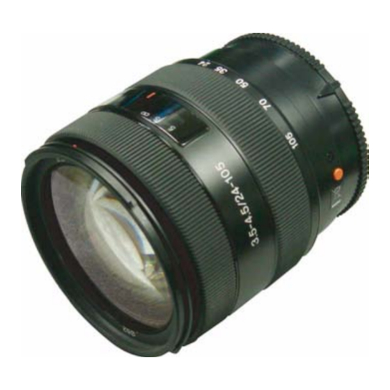
SAL24105 (3.5-4.5/24-105) (24-105mm F3.5-4.5)
9-852-111-15
(3.5-4.5/24-105) (24-105mm F3.5-4.5)
DISASSEMBLY
REPAIR PARTS LIST
Sony EMCS Co.
SAL24105
Canadian Model
Chinese Model
ADJUSTMENTS
LENS FOR DSLR CAMERA
US Model
AEP Model
2008C0800-1
© 2008.03
Published by Kohda TEC
Advertisement
Table of Contents

Related Manuals for Sony SAL24105


Summary of Contents for Sony SAL24105
- Page 1 Manual. Link Link SPECIFICATIONS DISASSEMBLY ADJUSTMENTS SERVICE NOTE REPAIR PARTS LIST • About the Lens Test Projector and Finished Inspection JIG LENS FOR DSLR CAMERA 2008C0800-1 SAL24105 (3.5-4.5/24-105) (24-105mm F3.5-4.5) © 2008.03 Sony EMCS Co. 9-852-111-15 Published by Kohda TEC...
- Page 2 Mass (g (oz.)) Approx. 395 (13 15/16) Included items Lens (1), Front lens cap (1), Rear lens cap (1), Lens hood (1), Set of printed documentation Designs and specifications are subject to change without notice. SAL24105 (3.5-4.5/24-105) (24-105mm F3.5-4.5) — 2 —...
-
Page 3: Table Of Contents
Focus-shift Check/Adjustment (Aperture (Amount of Spherical Aberration)) ·················································· 4-27 4-8. Lens ROM Check ························································· 4-28 4-9. Zoom Brush Position Check/Adjustment and Pattern Check ······························································· 4-30 4-10. Focus Brush Position Check/Adjustment and Pattern Check ······························································· 4-38 SAL24105 (3.5-4.5/24-105) (24-105mm F3.5-4.5) — 3 —... -
Page 4: Service Note
IC pins, etc. • Be sure to control soldering iron tips used for unleaded solder and those for leaded solder so they are managed separately. Mixing unleaded solder and leaded solder will cause detachment phenomenon. SAL24105 (3.5-4.5/24-105) (24-105mm F3.5-4.5) -
Page 5: Safety Check-Out
CRITIQUES POUR LA SÉCURITÉ DE FONCTIONNEMENT. NE COMPONENTS WITH SONY PARTS WHOSE PART NUMBERS REMPLACER CES COMPOSANTS QUE PAR DES PIÈSES SONY APPEAR AS SHOWN IN THIS MANUAL OR IN SUPPLEMENTS DONT LES NUMÉROS SONT DONNÉS DANS CE MANUEL OU PUBLISHED BY SONY. -
Page 6: Troubleshooting
Replace the lens mount block. diameter adjustment. (See page 4-16.) Replace the lens mount block. Check the aperture operation of 4 group lens block. Replace the 4 group lens block. Perform the aperture diameter check. (See page 4-13.) SAL24105 (3.5-4.5/24-105) (24-105mm F3.5-4.5) - Page 7 Clean the board pattern of zoom flex pattern. Check the operation again. Replace the main flexible PC board block. Perform the zoom brush position check/adjustment. (See page 4-30.) SAL24105 (3.5-4.5/24-105) (24-105mm F3.5-4.5)
- Page 8 Clean the board pattern. Replace the defective part or apply the grease. Replace the main flexible PC board block. Check the operation again. Perform the focus brush position check/adjustment and pattern check. (See page 4-38.) SAL24105 (3.5-4.5/24-105) (24-105mm F3.5-4.5)
-
Page 9: Disassembly
Match the universal wrench to the holes or notches of the lens block, etc. Chip-A Match the universal wrench Universal wrench to the width of holes or notches. Chip-A Notches Chip-B Chip Chip Chip-B Holes SAL24105 (3.5-4.5/24-105) (24-105mm F3.5-4.5) - Page 10 Gear (C, D) Block Decoration Cover 7 Zoom Brush Set Tape B ZOOM BRUSH POSITION HELP02 ADJUSTMENT Decoration Cover Set Tape HELP03 5 Zoom Ring Reinforcement HELP02 1 Decoration Plate Plate Polyester Tape (Black) 10mm HELP01 SAL24105 (3.5-4.5/24-105) (24-105mm F3.5-4.5)
- Page 11 HELP24 1st Lens Barrel HELP15 Guide Roller 8 Torque Ring Friction Sheet HELP14 HELP23 First Moving Screw (Nut) Frame 7 Focus Ring B HELP12 HELP14 HELP22 6 Torque Ring Spring HELP14 1 Group Lens Block HELP13 SAL24105 (3.5-4.5/24-105) (24-105mm F3.5-4.5)
- Page 12 HELP27 4 Focus Stopper FOCUS-SHIFT ADJUSTMENT !- Focus Cam Tube HELP27 Block HELP34 FOCUS SCALE 3 Focus Operating Lever PLATE POSITION ADJUSTMENT Focus Scale HELP29 HELP26 Plate Polyester Tape (Black) 10mm 1 Light Shield Plate A SAL24105 (3.5-4.5/24-105) (24-105mm F3.5-4.5)
- Page 13 4 Aperture Block 2nd Moving Frame Guide Roller APERTURE DIAMETER ADJUSTMENT Aperture Blade Holding Ring HELP37 3 Aperture Unit Holding Spring HELP36 1 Light Shield HELP35 2 2 group Lens Block Sheet A Polyester Tape (Black) 10mm SAL24105 (3.5-4.5/24-105) (24-105mm F3.5-4.5)
- Page 14 Anti Slip Spring Flexible Substrate Set Tape F HELP42 HELP43 2 Focus Connect Ring Insulating Tape 4 Main Flexible PC Board Block HELP41 HELP44 1 Gear (A, B) Block HELP41 Appearance Shape of Main Flexible PC Board Block SAL24105 (3.5-4.5/24-105) (24-105mm F3.5-4.5)
- Page 15 Note for assembling and grease applying positions are shown. HELP01 Affix the decoration plate, aligning its “/” of “3.5 - 4.5/24 - 105” with the index line of focus scale window unit. Decoration Plate Index Line Focus Scale Window Unit SAL24105 (3.5-4.5/24-105) (24-105mm F3.5-4.5) HELP...
- Page 16 Affix the outer cover to the fixed holding tube block, inserting its projections in the grooves and window of fixed holding tube block. Projection (inner) Projection (inner) Outer Cover Projection Window Groove Groove Fixed Holding Tube Block SAL24105 (3.5-4.5/24-105) (24-105mm F3.5-4.5) HELP...
- Page 17 After adjusting the zoom brush position adjustment, affix the polyester tapes (black) 10mm cut as instructed to the position shown in the figure. Note: For zoom brush position adjustment, refer to P.4-30. Zoom Control Tube Polyester Tape (Black) 10mm (6x50mm) Zoom Brush SAL24105 (3.5-4.5/24-105) (24-105mm F3.5-4.5) HELP...
- Page 18 Screw Hole HELP06 Adhesive bond (B-40): J-6082-614-A Apply the adhesive bond (B-40) to the tips of three screws and tighten them as shown in the figure. Apply the adhesive bond (B-40) Apply the adhesive bond (B-40) SAL24105 (3.5-4.5/24-105) (24-105mm F3.5-4.5) HELP...
- Page 19 Apply the anti-diffusion agent (A-20) Stopper Screw Lens Mount Block Apply the LOCTITE 460 Insert the preset ring guide assy in the iris control plate and attach the main SP guide riveting block. Iris Control Tube SAL24105 (3.5-4.5/24-105) (24-105mm F3.5-4.5) HELP...
- Page 20 Apply the grease (G-15) Apply the grease (G-85) HELP10 Apply the anti-diffusion agent (A-20) to the entire circumference of indicated portion of 4 group lens block. 4 group Lens Block Apply the anti-diffusion agent (A-20) SAL24105 (3.5-4.5/24-105) (24-105mm F3.5-4.5) HELP...
- Page 21 Lead Groove Attach the 1st lens barrel holder, aligning the hole of zoom ring with the nut (B) by rotating the first moving frame. Zoom Ring 1st Moving Frame Hole Nut (B) 1st Lens Barrel Holder SAL24105 (3.5-4.5/24-105) (24-105mm F3.5-4.5) HELP...
- Page 22 Apply the adhesive bond (B-10) to three nuts and insert them in the 1 group lens block. Apply the anti-diffusion agent (A-20) to the indicated portion of 1 group lens block. Apply the adhesive bond (B-10) Apply the anti-diffusion agent (A-20) Apply the grease (G-85) 1 Group Lens Block SAL24105 (3.5-4.5/24-105) (24-105mm F3.5-4.5) HELP...
- Page 23 (Slider of 1 group lens frame, six locations) Apply the grease (G-115) (Guide roller groove of 1st lens barrel holder, three locations) Apply the grease (G-115) (Slider of 1 group lens frame, six locations) Apply the anti-diffusion agent (A-20) First Moving Frame SAL24105 (3.5-4.5/24-105) (24-105mm F3.5-4.5) HELP...
- Page 24 Apply the adhesive bond (B-40) Scratch Prevention Sheet Pinch Lever B Pinch Lever (Pinch Lever C) MF Operation Ring Apply the adhesive bond (B-40) Apply the adhesive bond (B-40) Torque Ring Cut Pattern MF Operation Cut Pattern Ring SAL24105 (3.5-4.5/24-105) (24-105mm F3.5-4.5) HELP...
- Page 25 Apply the anti-diffusion agent (A-20) to the indicated portion (entire circumference) of torque hold ring. Apply the grease (G-15) and grease (G-115) to the indicated portion (entire circumference) of torque hold ring. Apply the grease (G-115) Apply the anti-diffusion agent (A-20) Apply the grease (G-15) Torque Hold Ring SAL24105 (3.5-4.5/24-105) (24-105mm F3.5-4.5) HELP...
- Page 26 Apply the grease (G-115) to the indicated portion (entire circumference) of focus ring B. Focus Ring B Apply the grease (G-115) Insert the focus ring B, aligning its projection with the cut portion of focus ring. Projection Focus Ring B Focus Ring Torque Ring Cut Portion SAL24105 (3.5-4.5/24-105) (24-105mm F3.5-4.5) HELP...
- Page 27 After adjusting the focus brush, tighten two screws to fix the focus brush, and apply the adhesive bond (B-10) to the indicated portion. Note: For focus brush adjustment, refer to P.4-38. Focus Brush Fixed Holding Tube Block Apply the adhesive bond (B-10) SAL24105 (3.5-4.5/24-105) (24-105mm F3.5-4.5) HELP...
- Page 28 Apply the adhesive bond to the tips of two screws and tighten them as shown in figure. Focus Cam Tube Block Forked Portion Focus Joint Tube 2 group Lens Block Focus Operating Lever Apply the adhesive bond (B-40) SAL24105 (3.5-4.5/24-105) (24-105mm F3.5-4.5) HELP...
- Page 29 Chip of Focus Inner Gear Projection Projection Cut Portion Fixed Holding Tube Block Cut Portion Rotate clockwise the focus ring so that distance tube gear engages with the gear block (A, B) lock. Focus Ring SAL24105 (3.5-4.5/24-105) (24-105mm F3.5-4.5) HELP...
- Page 30 Insert the focus stopper in the gap between the fixed holding tube block and the focus ring as shown in the figure. Focus Stopper Focus Ring Fixed Holding Tube Block After focus-shift adjustment, apply the adhesive bond (B-10) to the two screws of focus stopper. Note: Perform focus-shift adjustment, refer to 4-25 page. SAL24105 (3.5-4.5/24-105) (24-105mm F3.5-4.5) HELP...
- Page 31 Affix the polyester tape (black) 10mm of size shown in the figure to the position shown in the figure. Apply the grease (G-85) to the indicated portion shown in the figure. Focus Ring Gear Apply the grease (G-85) Focus Ring Polyester Tape (Black) 10mm (5x10mm) SAL24105 (3.5-4.5/24-105) (24-105mm F3.5-4.5) HELP...
- Page 32 Set the focus cam tube block to the Wide end by rotating it counterclockwise, and set the zoom ring to the Wide end. Insert the linear guide key A and linear guide key B in the key groove of focus cam tube block. Key Groove Key Groove Focus Cam Tube Block SAL24105 (3.5-4.5/24-105) (24-105mm F3.5-4.5) HELP...
- Page 33 Rotate counterclockwise the zoom ring a little and tighten the zoom operating pin, aligning the “U” shaped groove with the screw hole of focus cam tube. Zoom Ring Projection Fixed Holding Tube Block Index Block Cut Portion Screw Hole of Focus Cam Tube U Shaped Groove Zoom Ring SAL24105 (3.5-4.5/24-105) (24-105mm F3.5-4.5) HELP...
- Page 34 Do not apply the grease to the 1/2 area of cam groove near the main flexible PC board block and the slider groove of zoom ring at the lower side of main flexible PC board block. Apply the grease (G-85) Apply the grease (G-85) Fixed Holding Tube Block SAL24105 (3.5-4.5/24-105) (24-105mm F3.5-4.5) HELP...
- Page 35 After installation, rotate the focus cam tube block in the arrow direction. Cut Portion Fixed Holding Tube Block Gear (C, D) Block Insertion Block Projection Linear Guide Key Focus Cam Tube Block Focus Cam Tube Block Fixed Holding Tube Block SAL24105 (3.5-4.5/24-105) (24-105mm F3.5-4.5) HELP...
- Page 36 Set the focus cam tube block to “Tele end” by rotating the cam tube in the arrow direction. Insert the focus operating lever installing block in the focus cam tube block, aligning. 2nd Lens Block Focus Operating Lever Installing Block Straight Groove Focus Cam Tube Block SAL24105 (3.5-4.5/24-105) (24-105mm F3.5-4.5) HELP...
- Page 37 Perform aperture diameter adjustment, referring to 4-16 page. Cut Portion Aperture Unit Holding Spring Focus Cam Tube Opening Aperture Operating Plate Aperture Blade Aperture Blade Holding Ring Aperture Unit Holding Spring Apply the adhesive bond (B-10) SAL24105 (3.5-4.5/24-105) (24-105mm F3.5-4.5) HELP...
- Page 38 Rotate the aperture blade holding ring in the arrow direction so that it disappears from the cut portion of focus cam tube block (state of iris close) as shown in the figure. Preset Lever of Aperture Operating Plate Focus Cam Tube Block Cut Portion Cut Portion Preset Lever Aperture Blade Holding Ring Focus Cam Tube Block SAL24105 (3.5-4.5/24-105) (24-105mm F3.5-4.5) HELP...
- Page 39 Attach the last aperture blade, releasing the blade installed first in the arrow direction. Aperture Blade Aperture Blade Boss Boss Apply the anti-diffusion (A-20) (Entire circumference) Boss Hole Aperture Blade Holding Ring Boss Hole Aperture Blade Holding Ring SAL24105 (3.5-4.5/24-105) (24-105mm F3.5-4.5) HELP...
- Page 40 Then, rotate it in the arrow direction. Cut Portion Projection Bearing Press Fitting Block Bearing of Gear Bearing Press Fitting Block Gear Focus Connect Ring Hook Anti Slit Spring SAL24105 (3.5-4.5/24-105) (24-105mm F3.5-4.5) HELP...
- Page 41 Grease (G-115): J-682-627-A Apply the grease (G-15), grease (G-85) and grease (115) to the indicated portions of focus connect ring. Apply the grease (G-115) Apply the grease (G-15) Apply the grease (G-85) Focus Connect Ring SAL24105 (3.5-4.5/24-105) (24-105mm F3.5-4.5) HELP...
- Page 42 When affixing, use “a” and “b” as references. Affix the DV encoder block in parallel with the edge surface of bearing press fitting block. Main Flexible PC Board Block Bearing Press Fitting Block Zoom Encoder DV Encoder Hole SAL24105 (3.5-4.5/24-105) (24-105mm F3.5-4.5) HELP...
- Page 43 Apply the grease (G-115) to the indicated portion of bearing press fitting block. Bearing Press Fitting Block Apply the grease (G-115) (Press-fitted portion of focus ring) Apply the grease (G-115) (Focus inner gear) Apply the grease (G-115) (Press-fitted portion of focus connect ring) SAL24105 (3.5-4.5/24-105) (24-105mm F3.5-4.5) HELP...
- Page 44 Apply the adhesive bond (B-10) to the 2 locations of all circumference of 4 group lens block and 4th lens hold washer. 4th Lens Holder Block 4 Group Lens Block Apply the adhesive bond (B-10) Apply the adhesive bond (B-10) (2 locations of all circumference, width 5mm) (2 locations of all circumference, width 5mm) SAL24105 (3.5-4.5/24-105) (24-105mm F3.5-4.5) HELP...
-
Page 45: Repair Parts List
2-688-399-01 RUBBER (ZOOM RUBBER RING) A-1207-248-A BLOCK, MAIN SP GUIDE RIVETING 2-688-406-01 MAIN SPRING 2-688-400-01 COVER (OUTER COVER) A-1207-253-A UNIT(FOCUS SCALE WINDOW UNIT) A-1194-992-A PRESET RING GUIDE ASSY 2-688-248-01 SHAFT (AF COUPLER) 2-684-234-01 PRESET RING HOLDING PLATE 2-684-244-01 STOPPER SCREW SAL24105 (3.5-4.5/24-105) (24-105mm F3.5-4.5) - Page 46 Selection parts SPRING (TORQUE RING SPRING (A to C)) (Note 2) 2-688-272-01 FRICTION SHEET 2-688-363-01 RING (TORQUE HOLD RING) 2-688-345-01 SCREW (NUT) 2-688-311-01 SHEET (SCRATCH PREVENSION) A-1207-250-A BLOCK, 1 GROUP LENS Selection parts PINCH LEVER (or C) (Note 1) 2-898-685-01 4TH LENS HOLD WASHER SAL24105 (3.5-4.5/24-105) (24-105mm F3.5-4.5)
- Page 47 2-688-212-01 LEVER (LINEAR GUIDE KEY A) 9-913-210-03 POLYESTER TAPE (BLACK) 10mm (Note 1) 2-688-150-01 RING(FOCUS RING) 2-684-762-01 PHI3 HEAD SCREW M1.6X2.5 2-887-123-01 SCREW, M1.4X1.6 P1 2-688-396-01 PLATE (FOCUS SCALE PLATE) 3-218-506-01 ZOOM, OPERATING, PIN B 2-688-221-01 FOCUS BRUSH 2-688-259-01 FOCUS STOPPER SAL24105 (3.5-4.5/24-105) (24-105mm F3.5-4.5)
- Page 48 9-913-210-03 POLYESTER TAPE (BLACK) 10mm (Note 2) 2-688-410-01 APERTURE UNIT HOLDING SPRING 2-685-585-01 PHI4 HEAD SCREW M1.6X2.5 A-1207-241-A BLOCK, 2 GROUP LENS 2-684-762-01 PHI3 HEAD SCREW M1.6X2.5 2-688-260-01 PIN(2ND MOVING FRAME GUIDE PIN) A-1207-237-A BLOCK, FOCUS CAM TUBE SAL24105 (3.5-4.5/24-105) (24-105mm F3.5-4.5)
- Page 49 2-688-317-01 SHEET(FLEXIBLE SUBSTRATE SET F) 2-688-316-01 FLEXIBLE SUBSTRATE SET TAPE E 2-688-326-01 FLEXIBLE SUBSTRATE SET TAPE G 2-688-211-01 ANTI SLIP SPRING * 213 9-913-210-01 INSULATING TAPE (Note 1) 2-688-152-01 FOCUS CONNECT RING A-1207-243-A BLOCK,(BEARING) PRESS FITTING SAL24105 (3.5-4.5/24-105) (24-105mm F3.5-4.5)
- Page 50 Use the pinch lever usually, replace the pinch lever C when focus clucth mecha- nism runs idle. In case use pinch lever C, replace with two it. Part No. Description 2-688-255-01 PINCH LEVER 2-688-258-01 LEVER (PINCH LEVER C) SAL24105 (3.5-4.5/24-105) (24-105mm F3.5-4.5)
-
Page 51: Supplied Accessories
(JAPANESE, ENGLISH, FRENCH, SPANISH, SIMPLIFIED CHINESE) 2-686-120-11 MANUAL, INSTRUCTION (GERMAN, DUTCH, SWEDISH, ITALIAN) (AEP) 2-686-120-21 MANUAL, INSTRUCTION (PORTUGUESE, RUSSIAN, TRADITIONAL CHINESE, KOREAN, ARABIC) (AEP) Lens Hood (SH0016) Front Lens Cap 2-687-332-01 2-687-233-01 Rear Lens Cap 2-683-615-01 SAL24105 (3.5-4.5/24-105) (24-105mm F3.5-4.5) -
Page 52: Adjustments
(43.50mm) J-6082-607-A J-6082-608-A J-6082-640-A J-10 J-11 J-12 Finished Aberration Inspection Universal wrench measuring cap J-6082-609-A 62mm (SAL24105) J-6082-645-A J-6082-646-A (Note 4) J-13 J-14 Chip-A for Chip-B for universal wrench: universal wrench: J-6082-609-1 J-6082-609-2 Fig. 4-1-1 SAL24105 (3.5-4.5/24-105) (24-105mm F3.5-4.5) - Page 53 Attach the chart to the 1000 mm collimator as shown in Fig. 4-1-2. Align the marks Chart 1000 mm collimator Fig. 4-1-2 Note 3: Connect the variable transformer (Output voltage: AC 100 V) to the lens test projector. Note 4: Finished Inspection JIG is AC 100 V only. SAL24105 (3.5-4.5/24-105) (24-105mm F3.5-4.5)
- Page 54 Fig.4-1-3 Download the file from Service Fixture and Software of ESI homepage, and save it in “C:\MCC”. Double-click the downloaded file “InstaCal.exe”to extract it. [Browse...] The window to specify the extract destination folder appears. Click Fig.4-1-4 SAL24105 (3.5-4.5/24-105) (24-105mm F3.5-4.5)
- Page 55 6) The window returns to the menu to specify the extract destination folder. Click Fig.4-1-6 7) When the window below appears, click [OK]. Fig.4-1-7 [Close] 8) Return to the menu to specify the extract destination folder. Then, click to close the window. SAL24105 (3.5-4.5/24-105) (24-105mm F3.5-4.5)
- Page 56 2. Setup of PC Card Double-click “InstaCal.exe” in “C:\MCC” folder to begin the installation. Fig.4-1-8 [Next>] The menu to begin the installation appears. Click Fig.4-1-9 [Next>] Specify the install destination folder. As the default is used for it, click Fig.4-1-10 SAL24105 (3.5-4.5/24-105) (24-105mm F3.5-4.5)
- Page 57 Fig.4-1-12 6) To make the configuration installed effective, the window to prompt the restart appears. Click “Yes” to restart the PC. Note: If a device is connected without restarting, the program may not work properly. Fig.4-1-13 SAL24105 (3.5-4.5/24-105) (24-105mm F3.5-4.5)
- Page 58 After restarting the PC, insert the PC-CARD-DIO48 in the PC card slot. The software installation window appears. Click “Install the software automatically. (Recommended)”. Fig.4-1-14 [Finish] The software is detected and installed. When the window below appears, click to terminate the installation. Fig.4-1-15 SAL24105 (3.5-4.5/24-105) (24-105mm F3.5-4.5)
- Page 59 Depending on the slot inserted, the slot No. differs. Fig.4-1-17 3) Confirm that “PC-CARD-DIO48” is recognized as “Board#0”. Note: If not recognized as “Board#0”, the program does not work properly. Fig.4-1-18 4) Click “File” - “Exit” to terminate “InstaCal”. SAL24105 (3.5-4.5/24-105) (24-105mm F3.5-4.5)
- Page 60 Download the file “ActuatorChecker VerX.X.X.X.zip” from Service Fixture and Software of ESI homepage, save and extract it. Start up “ActuatorChecker.exe” from an arbitrary folder. If “PC-CARD-DIO48” is properly installed, the window below appears. Note: The version of “ActuatorCheker” might be updated. Fig.4-1-19 SAL24105 (3.5-4.5/24-105) (24-105mm F3.5-4.5)
- Page 61 Lens Fig.4-1-20 Turn on the finished inspection JIG. Turn on the personal computer. Start up “ActuatorChecker.exe” from an arbitrary folder, conform that start up program normally. Note: Turn off the finished inspection jig after use. SAL24105 (3.5-4.5/24-105) (24-105mm F3.5-4.5) 4-10...
- Page 62 Depending on the initial startup or setting made at the previous startup, the window differs.When the English window appears, click [Set up] button. Note: When any button is clicked, the Serial window appears. The window to enter the lens serial number appears. Fig.4-1-22 SAL24105 (3.5-4.5/24-105) (24-105mm F3.5-4.5) 4-11...
- Page 63 [START] Click from the start up window when you inspect the corresponding model as everything continues. The procedure for executing the inspection of each item one by one has been described in this manual. SAL24105 (3.5-4.5/24-105) (24-105mm F3.5-4.5) 4-12...
-
Page 64: Aperture Diameter Check/Adjustment
Luminance: EV11 Setting of Lens: Zoom: Wide end (focal length: 24mm) Focus: Infinity end Setting of Camera: ISO: Exposure Mode: shutter Speed: 1/125 Aperture: F5.6 Focus Mode: Metering: Center weighted Preset white balance: Tungsten D-R: SAL24105 (3.5-4.5/24-105) (24-105mm F3.5-4.5) 4-13... - Page 65 3) Set the Color Calculator 2 as follows. Measured value display (Display menu): RGB+L*a*b* Measuring method (Display menu): Center Single Area Fig.4-2-4 Color space (Edit menu): sRGB Fig.4-2-5 Area size for calculate (Edit menu →Option): 256×256 Pixels Fig.4-2-6 SAL24105 (3.5-4.5/24-105) (24-105mm F3.5-4.5) 4-14...
- Page 66 Aperture error = Average “G” value of checking lens (b) - Average “G” value of master lens (a) Specification Aperture error = –15 to +10 (Wide end: 24mm) When the aperture error is out of specification, perform “4-2-2. Aperture Diameter Adjustment”. SAL24105 (3.5-4.5/24-105) (24-105mm F3.5-4.5) 4-15...
- Page 67 2) Set the zoom to 105 mm. 3) Attach the maximum aperture jig, and open iris . Zoom Ring Rear Light Shield Barrel Lens Mount Block Fixed Holding Tube Block Focus Cam Tube Block Fig.4-2-8 SAL24105 (3.5-4.5/24-105) (24-105mm F3.5-4.5) 4-16...
- Page 68 Check the tolerance of iris again and repeat the adjustment/check until the tolerance of iris meets the specification. After completing the adjustment, apply the adhesive bond (B-10) to three indicated portions. Aperture Blade Holding Ring Preset Lever Preset Ring Apply the adhesive bond (B-10) Fig.4-2-9 SAL24105 (3.5-4.5/24-105) (24-105mm F3.5-4.5) 4-17...
-
Page 69: Projective Resolving Power Check/Adjustment
Fixed lever Lens Heat-absorbing filter Chart Chart Filament Filament f=18 to 35 mm f=100 to 200 mm Fixed lever Chart Chart Filament Filament f=35 to 100 mm f=200 to 300 mm Lens test projector Fig.4-3-1 SAL24105 (3.5-4.5/24-105) (24-105mm F3.5-4.5) 4-18... - Page 70 Turn the focus ring of the checking lens until the chart image projected on the screen is the sharpest at the center (y’=0). Set the plane mirror to the center of the projected image (y’= 0), and adjust the projector position so that the mirror reflects the light to the center of the lens. SAL24105 (3.5-4.5/24-105) (24-105mm F3.5-4.5) 4-19...
- Page 71 125 or greater — — 40 or greater 32 or greater 40 or greater 25 or greater 125 or greater — — 40 or greater 25 or greater 40 or greater 25 or greater Table 4-3-2 SAL24105 (3.5-4.5/24-105) (24-105mm F3.5-4.5) 4-20...
- Page 72 Set the focal length of lens to 105 mm and adjust the focus so that the center “y’= 0” reaches the maximum resolution. Check projective resolving power at reach peripheral point of “y’= 18”. If the projective resolving power does not meet the specification, replace the 4 group lens block. SAL24105 (3.5-4.5/24-105) (24-105mm F3.5-4.5) 4-21...
- Page 73 Focus on fine lines on the surface. Fig.4-4-2 5) Turn the scale ring of the dial gauge until the long pointer indicates “0”. Note: This position is the flange back (f’F) = 43.5 mm. Memorize the position of short-pointer. SAL24105 (3.5-4.5/24-105) (24-105mm F3.5-4.5) 4-22...
- Page 74 (mm) 44.55 to 44.77 44.55 to 44.80 44.55 to 44.95 Table 4-4-1 When the flange back (f’F) of the checking lens is out of specification of the Table 4-4-1, perform “4-4-2. Focus-shift/Flange Back (f’F) Adjustment”. SAL24105 (3.5-4.5/24-105) (24-105mm F3.5-4.5) 4-23...
- Page 75 COUPLER ADJUSTMENT WASHER 0.05 2-684-058-01 COUPLER ADJUSTMENT WASHER 0.07 2-684-059-01 COUPLER ADJUSTMENT WASHER 2-684-060-01 COUPLER ADJUSTMENT WASHER 2-684-061-01 COUPLER ADJUSTMENT WASHER Table 4-4-3 7) Insert the back adjustment washer, and perform “4-4-1. Flange back (f’F) Check”. SAL24105 (3.5-4.5/24-105) (24-105mm F3.5-4.5) 4-24...
-
Page 76: Focus-Shift (By Zooming) Check/Adjustment
Apply the adhesive bond (B-10) Focus Stopper Fixed Holding Tube Block Fig.4-5-1 Repeat steps 2) to 5) until the value meets the specification. After completing the adjustment, apply the adhesive bond (B-10) to the locations shown in the figure. SAL24105 (3.5-4.5/24-105) (24-105mm F3.5-4.5) 4-25... -
Page 77: Focus Scale Plate, Position Adjustment
3) Return a little the focus ring, and apply the adhesive bond (B-10) to the location shown in the figure. Focus Scale Plate Focus Scale Plate White Line Marking-off Line Focus Ring Apply the adhesive bond (B-10) Fixed Holding Tube Block Fig.4-6-1 SAL24105 (3.5-4.5/24-105) (24-105mm F3.5-4.5) 4-26... -
Page 78: Focus-Shift Check/Adjustment
• 1000 mm Collimator • Flange Back Tester • A-mount Attachment • Flange Back Gauge (43.50mm) • Aberration measuring cap 62mm (SAL24105) 1. Preparations Perform “1. Preparations” of “4-4-1. Flange Back (f’F) Check”. Set the checking lens focus to the infinite. -
Page 79: Lens Rom Check
1) Click Fig.4-8-1 2) The Serial window appears. Input the lens serial number. [OK] Note: When is clicked without inputting the serial number, the date executed is displayed on the completion window of each item. Fig.4-8-2 SAL24105 (3.5-4.5/24-105) (24-105mm F3.5-4.5) 4-28... - Page 80 • 4-10-1. Focus Brush Position Adjustment (Search Focus Adjustment Point) • Cleaning of flexible pattern or the brush. • Replaceing the brush. • Replaceing the main flexible unit. Perform “2. Checking Method” again, repeat the inspection until “OK” appears on the pop-up window. SAL24105 (3.5-4.5/24-105) (24-105mm F3.5-4.5) 4-29...
-
Page 81: Zoom Brush Position Check/Adjustment And Pattern Check
Polyester Tape (Black) 10mm (8x25 mm) Fig.4-9-2 3) Connected to equipment with checking lens. (Refer to Section 4-1-3.) 4) Start up of “ActuatorChecker.exe”. [Set up] 5) Click , and perform the initial setting. (Refer to Section 4-1-4.) SAL24105 (3.5-4.5/24-105) (24-105mm F3.5-4.5) 4-30... - Page 82 Move the brush right and left to adjust. At this moment, be careful not to shift the position by shock when touching to the zoom. Zoom Brush Zoom Brush Flexible Board (Pattern (trace) Side) Fig.4-9-5 SAL24105 (3.5-4.5/24-105) (24-105mm F3.5-4.5) 4-31...
- Page 83 2) If the “NG” appears again, thought cause communication error of the finished inspection JIG and checking lens, confirm or perform the following. • Improper connection of connector. • Improper of BL contact. • Disconnection of mirror box fixture. SAL24105 (3.5-4.5/24-105) (24-105mm F3.5-4.5) 4-32...
- Page 84 Fig.4-9-10 The message “Move ZOOM to WIDE position. Then push [ENTER].” is displayed on the pop-up window. Set the zoom to the wide position and press down the ENTER key. Fig.4-9-11 SAL24105 (3.5-4.5/24-105) (24-105mm F3.5-4.5) 4-33...
- Page 85 • 4-9-1. Zoom Brush Position Adjustment (Search Zoom Adjustment Point) • Cleaning of flexible pattern or the brush. • Replaceing the brush. 3) Perform “2. Checking Method”again, repeat the inspection until “OK” appears on the pop-up window. SAL24105 (3.5-4.5/24-105) (24-105mm F3.5-4.5) 4-34...
- Page 86 Fig.4-9-19 The message “Move ZOOM to TELE position. Then push [ENTER].” is displayed on the pop-up window. Set the zoom to the tele position and press down the ENTER key. Fig.4-9-20 SAL24105 (3.5-4.5/24-105) (24-105mm F3.5-4.5) 4-35...
- Page 87 • Replaceing the brush. • Rotating operation error of the focus ring (rotation speed is not suitable at a regulated speed.). 3) Perform “2. Checking Method”again, repeat the inspection until “OK” appears on the pop-up window. SAL24105 (3.5-4.5/24-105) (24-105mm F3.5-4.5) 4-36...
- Page 88 • When the zoom pattern error Fig.4-9-29 Fig.4-9-30 • When the lens does not reach the tele end infinity position seconds. Fig.4-9-31 Perform “2. Checking Method”again, repeat the inspection until “OK” appears on the pop-up window. SAL24105 (3.5-4.5/24-105) (24-105mm F3.5-4.5) 4-37...
-
Page 89: Focus Brush Position Check/Adjustment And
[Set up] 4) Click , and perform the initial setting. (Refer to Section 4-1-4.) 2. Adjusting Method 1) Set the focus position to infinity position. 2) Loosen two screws fixing the brush base plate. Screws Fig.4-10-2 SAL24105 (3.5-4.5/24-105) (24-105mm F3.5-4.5) 4-38... - Page 90 If the “NG” appears again, thought cause communication error of the finished inspection JIG and checking lens, confirm or perform the following. • Improper connection of connector. • Improper of BL contact. • Disconnection of mirror box fixture. SAL24105 (3.5-4.5/24-105) (24-105mm F3.5-4.5) 4-39...
- Page 91 Fig.4-10-8 3) The message “Move FOCUS to Near position. Then push [ENTER].” is displayed on the pop-up window. Set the focus to the near position and press down the ENTER key. Fig.4-10-9 SAL24105 (3.5-4.5/24-105) (24-105mm F3.5-4.5) 4-40...
- Page 92 • 4-10-1. Focus Brush Position Adjustment (Search Focus Adjustment Point) • Cleaning of flexible pattern or the brush. • Replaceing the brush. Perform “2. Checking Method”again, repeat the inspection until “OK” appears on the pop-up window. SAL24105 (3.5-4.5/24-105) (24-105mm F3.5-4.5) 4-41...
- Page 93 Fig.4-10-17 3) The message “Move FOCUS to Infinity position. Then push [ENTER].” is displayed on the pop-up window. Set the focus to the infinity position and press down the ENTER key. Fig.4-10-18 SAL24105 (3.5-4.5/24-105) (24-105mm F3.5-4.5) 4-42...
- Page 94 • Replaceing the brush. • Rotating operation error of the focus ring (rotation speed is not suitable at a regulated speed.). Perform “2. Checking Method”again, repeat the inspection until “OK” appears on the pop-up window. SAL24105 (3.5-4.5/24-105) (24-105mm F3.5-4.5) 4-43...
- Page 95 • When the focus pattern error Fig.4-10-27 Fig.4-10-28 • When the lens does not reach the infinity end infinity position seconds. Fig.4-10-29 2) Perform “2. Checking Method”again, repeat the inspection until “OK” appears on the pop-up window. SAL24105 (3.5-4.5/24-105) (24-105mm F3.5-4.5) 4-44...
- Page 96 [Description of main button functions on toolbar of the Adobe Acrobat Reader Ver5.0 (for Windows)] Toolbar Printing a text Reversing the screens displayed once • To reverse the previous screens (operation) one by one, click 1. Click the Print button 2.
- Page 97 (HELP22, HELP42) • Change of Specification (Page 4-20, 4-23) • Correction of Formula (Page 4-27) 2007.12 Revised-3 • Correction of Aperture Diameter Check (Page 4-13, 4-15) 2008.03 Revised-4 • Addition of Repair Parts (Page 3-2, 3-6) SAL24105 (3.5-4.5/24-105) (24-105mm F3.5-4.5)
Need help?
Do you have a question about the SAL24105 and is the answer not in the manual?
Questions and answers