Manhattan Comfort Hampton Manual
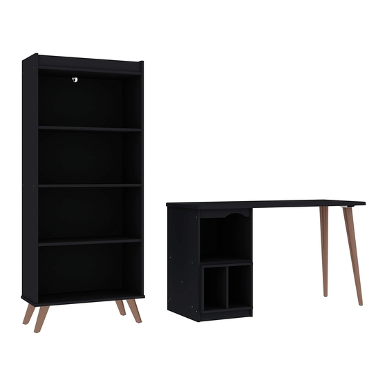
Home office desk 40.79"
Hide thumbs
Also See for Hampton:
- Quick start manual (8 pages) ,
- Technical information (7 pages) ,
- Manual (6 pages)

Related Manuals for Manhattan Comfort Hampton


Summary of Contents for Manhattan Comfort Hampton
- Page 1 888-230-2225 help@manhattancomfort.com 319 RIDGE RD, DAYTON, NJ08810, NEW JERSEY - UNITED STATES Hampton home office desk 40.79"...
-
Page 2: Technical Information
Technical information Maximum supported weight Dimension: W: 53.54" H: 29.92" D: 20.86" 20,86" 53,54" 22Lb 11,41" 19,60" 14,96" 11,02" 29,92" 6,61" 19,68" 11Lb ASSEMBLY VIDEO Tools needed (not included) - Page 3 FRONT VIEW REAR VIEW PART DESCRIPTION QUANTITY RIGHT SIDE FRAME SHELF CROSSBAR LEFT SIDE FEET BACK COVER TOP/ BASE OF THE NICHE SIDE OF THE NICHE HARDWARE...
- Page 4 STEP 1 - Insert the hardware (B) in the part (06). - Insert the hardware (F) in the parts (02, 04). STEP 2 - Connect the parts (01, 02, 03, 04, 05) with the hardware (A). STEP 3 - Connect the parts (01, 05) onto the part (06) with the hardware (C).
- Page 5 STEP 4 - Connect the hardware (H) under the part (06) with the hardware (G). - Then, screw the parts (07) into the hardware (H). STEP 5 - Connect the parts (09, 10) with the hardware (A). STEP 6 - Connect the niche onto the parts (02, 05) with the hardware (J).
- Page 6 888-230-2225 help@manhattancomfort.com 319 RIDGE RD, DAYTON, NJ08810, NEW JERSEY - UNITED STATES Hampton bookcase...
- Page 7 Technical information Maximum supported weight Dimension: W: 24.80" H: 60.12" D: 12.60" 11Lb ASSEMBLY VIDEO Tools needed (not included)
- Page 8 FRONT VIEW REAR VIEW PART DESCRIPTION QUANTITY RIGHT SIDE CROSSBAR FIXED SHELF LEFT SIDE BASE FEET BACK COVER (DRILLED) BACK COVER ADJUSTABLE SHELF HARDWARE...
- Page 9 STEP 1 - Insert the hardware (F) in the parts (02, 05). - Insert the hardware (G) in the part (03). STEP 2 - Connect the parts (01, 02, 03, 04) with the hardware (A). STEP 3 - Connect the part (05) onto the parts (01, 03, 04) with the hardware (A).
- Page 10 STEP 4 - Connect the part (06) onto the parts (02, 05) with hardware (A). STEP 5 - Insert the hardware (J) as showed on detail. - Connect the two parts (09) with the hardware (I+D). - Connect the parts (08, 09) with the hardware (I). STEP 6 USE THE GLUE (C) BEFORE FASTENING...
- Page 11 STEP 7 - Insert the parts (10) as showed above. STEP 8 Attention! This step is very important! You need to attach to the furniture on the wall to avoid any tip over risk. Follow the procedures as showed below. Pass the hardware (H) through the hole of the part (08) as shown in the figure.
Need help?
Do you have a question about the Hampton and is the answer not in the manual?
Questions and answers