
Related Manuals for ADC PG-FlexPlus FLL-814


Summary of Contents for ADC PG-FlexPlus FLL-814
- Page 1 Plus PG-Flex 24 Channel Integrated Central Office Line Unit Technical Practice Model List CLEI Code FLL-814 VACJK88E~~ VACJKPFE~~ Section SCP-FLL814-012-04H...
- Page 3 Information furnished by ADC is believed to be accurate and reliable. In no event shall ADC be liable for any damages resulting from the loss of data, loss of use, or loss of profits and ADC further disclaims any and all liability for indirect, incidental, special, consequential or other similar damages.
-
Page 4: Using This Technical Practice
• Unpack each container and visually inspect the contents for signs of damage. If the equipment has been dam- aged in transit, immediately report the extent of damage to the transportation company and to ADC. Order replacement equipment, if necessary. -
Page 5: Table Of Contents
PERFORMANCE — HDSL Summary ................PERFORMANCE — HDSL 24 Hour History ..............PERFORMANCE — HDSL 7 Day History ................ PERFORMANCE — ISDN Summary ................PERFORMANCE — ISDN 7 Hour History ................ Alarm Menu Options ....................... ALARMS — Alarms Summary ..................ADC Telecommunications, Inc. - Page 6 INFO — Help ........................112 Fault Isolation and Troubleshooting ..................113 Subscriber Reported Faults ....................115 Appendix A ..........................117 Acronyms ..........................119 Product Support ........................121 Technical Support ......................121 Limited Warranty ....................... 121 Returns ..........................121 ADC Telecommunications, Inc.
- Page 7 April 22, 2003 SCP-FLL814-012-04H FCC Class A Compliance ....................... 122 Modifications ........................122 ADC Telecommunications, Inc.
- Page 8 SCP-FLL814-012-04H April 22, 2003 ADC Telecommunications, Inc.
- Page 9 April 22, 2003 SCP-FLL814-012-04H List of Figures Figure 1. Typical IDLC Configuration ..................Figure 2. FLL-814 Front Panel ....................Figure 3. Terminal Menu and Display Structure ..............15 ADC Telecommunications, Inc.
- Page 10 SCP-FLL814-012-04H April 22, 2003 viii ADC Telecommunications, Inc.
- Page 11 Table 23. Timeslot Configuration Options ................102 Table 24. Test Menu Options ....................103 Table 25. Information Menu Options ..................107 Table 26. FLL-814 and FRL-842 Fault Isolation ..............113 Table 27. Subscriber Fault Isolating ..................115 ADC Telecommunications, Inc.
- Page 12 SCP-FLL814-012-04H April 22, 2003 ADC Telecommunications, Inc.
-
Page 13: Overview
Please refer to Appendix A on page 117 to facilitate proper system configuration. The Feature IMPORTANT Matrix identifies the major features in the CO and RT line units. The Compatibility Matrix provides CO and RT line unit compatibility information. ADC Telecommunications, Inc. -
Page 14: Description
The remote end of the system is housed in a RT Enclosure. RT enclosures are designed for outdoor and indoor applications and are provided with a diverse selection of mounting options. These enclosures support one or more systems that include one RT Line Unit and up to three RT Channel Units. ADC Telecommunications, Inc. -
Page 15: Functions And Features
April 22, 2003 SCP-FLL814-012-04H UNCTIONS AND EATURES The FLL-814 provides the following functions and features: • HDSL line transceivers and power supply • Front panel status indicators • Downloadable firmware • Mechanized Loop Test (MLT) • TR-909 Resistive Signatures ADC Telecommunications, Inc. -
Page 16: Hdsl Transmission
00:05. A minimum of 20 mA is drawn through each conductor of HDSL A and B during the time the sealing current feature is active. The current flow is ramped at a rate less than 20 mA/second to meet industry standard requirements for pulsed sealing current. ADC Telecommunications, Inc. -
Page 17: Subscriber Drop Testing
This test head reports its results using three-terminal signature resistors that are measured and converted to subscriber drop condition messages that can be viewed on the VT-100 terminal as described in TEST — Subscriber Drop Test on page 104. ADC Telecommunications, Inc. -
Page 18: Specifications
Temperature ° F to +150° F ° C to +65° C Humidity 5% to 95% (non-condensing) Physical Height 5.5 in. (14.0 cm.) Width 2.2 in. (5.6 cm.) Depth 10.25 in. (26.0 cm.) Weight 1.2 lbs. (0.5 kg.) ADC Telecommunications, Inc. -
Page 19: Power Consumption And Heat Dissipation
1.4 A HDSL Line Power On 1.9 A 11.9 A 15.8 A a. Indicates the COT shelf with one PMU-712, two PMX-744 and six FLL-814. b. Indicates the COT shelf with one PMU-712, two PMX-744 and eight FLL-814. ADC Telecommunications, Inc. -
Page 20: Front Panel
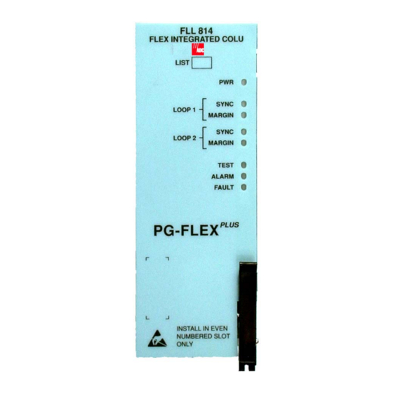
SCP-FLL814-012-04H April 22, 2003 RONT ANEL Figure 2 shows the FLL-814 front panel and Table 4 on page 9 describes the front panel LEDs. Status LEDs Retaining Latch Figure 2. FLL-814 Front Panel ADC Telecommunications, Inc. -
Page 21: Table 4. Fll-814 Front Panel Leds
Loop 2 margin at the FLL-814 and FRL-842 or Doubler Unit is above the provisioned threshold level Yellow Test active TEST Test not active FLL-814 alarm condition exist Flashing FRL-842 alarm condition exist ALARM No alarm conditions exist Fault in the FLL-814 FAULT No fault is detected ADC Telecommunications, Inc. -
Page 22: Installation And Test
Open the latch on the front of the FLL-814. Insert the FLL-814 into a vacant slot in the shelf that corresponds to the location of the wiring for the service being activated. Engage the retaining latch to hold the card in place. ADC Telecommunications, Inc. -
Page 23: Initialize And Power Up The Fll-814
• SYNC LEDs flash for approximately six seconds, then remains off • DSL Power Feed Short (PFS) alarm indicated in ALARMS — COLU System History on page 45 • FLL-814 waits one minute, then FLL-814 repeats startup sequence ADC Telecommunications, Inc. -
Page 24: Table 5. Fll-814 Led Status
It takes approximately two minutes before end-to-end synchronization is established with two doublers installed in the circuit. However, depending on the condition of the cable plant and length of the spans, it may take up to four minutes before synchronization is established. ADC Telecommunications, Inc. -
Page 25: Administration
– 1200, 2400, 4800, 9600, 19200, 38400, 57600, 115200 2. Connect the DB-9 cable between the RS-232 port on the front of the Management Unit and the PC/Laptop serial port. 3. Press several times until the Main Menu appears. ENTER ADC Telecommunications, Inc. -
Page 26: Navigational Methods
Selects an underlined or highlighted menu item A screen entry is made keys Some screens illustrated in this document may be slightly different than what may appear on the craft interface terminal. These differences are related to individual software installations. ADC Telecommunications, Inc. -
Page 27: Testing, Configuration, And Maintenance
ISPLAY TRUCTURE Figure 3 shows the menu structure of the terminal management system. In this software section, the COLU refers to the FLL-814 and the RTLU refers to the FRL-842. Figure 3. Terminal Menu and Display Structure ADC Telecommunications, Inc. -
Page 28: Log On The Fll-814 Through The Pmu-712
This screen logs the user into the FLL-814 by going through the PMU-712. The factory-default password is password#1. If the password has been changed and the new password is not known, contact ADC Technical Support while at the terminal. Technical Support will provide a temporary password based on the Access Key number displayed on the Logon screen. - Page 29 Log On The FLL-814 Through the PMU-712 (Continued) Step Action Type the Password, then press . After a successful login, the system banner screen appears for ENTER a few seconds. Then, the PMU-712 Main Menu screen appears. ADC Telecommunications, Inc.
- Page 30 SCP-FLL814-012-04H April 22, 2003 Log On The FLL-814 Through the PMU-712 (Continued) Step Action At the Main Menu, choose SELECT. Press to choose appropriate COLU# (e.g., COLU 2). ↓ The FLL-814 Main Menu appears. ADC Telecommunications, Inc.
- Page 31 April 22, 2003 SCP-FLL814-012-04H Log On The FLL-814 Through the PMU-712 (Continued) Step Action After 15 minutes of inactivity, the following menu appears. Press . The Login screen reappears. Repeat Step Step 3 Step 4 to log in again. ADC Telecommunications, Inc.
-
Page 32: Logout Of The Fll-814 Through The Pmu-712
At the FLL-814 Main Menu screen, press to return to the PMU-712 Main Menu. The following screen appears. At the Main Menu screen, select MAIN. Press to choose Logout. The following screen appears. ↓ ADC Telecommunications, Inc. - Page 33 April 22, 2003 SCP-FLL814-012-04H Performance Menu Options (Continued) Step Action To logout of the system, press The Login screen appears. ADC Telecommunications, Inc.
-
Page 34: Main Menu Option
SCP-FLL814-012-04H April 22, 2003 PTION The Main Menu provides system status (spans, services, channel status for each span and service). ADC Telecommunications, Inc. -
Page 35: Main
Table 7 on page 24 for System Status information. MAIN Step Action At the Main Menu screen, select MAIN. The following screen appears. To display channel status, press . The following screen appears. Press . The Main Menu screen reappears. ADC Telecommunications, Inc. -
Page 36: Table 7. System Status
Voice path through the system is intact, No CO battery detected (OPEN at CO, IDLE at RT) RING Line is ringing RINGGND Ring ground detected at the RT TEST Testing being done on line TKCOND Forced line condition RBAT Reverse battery ADC Telecommunications, Inc. -
Page 37: Performance Menu Options
The Performance Menu provides access to HDSL and ISDN status (if ISDN is installed) and performance monitoring information. Refer to Table 8 on page 26 for sub-menu options and descriptions, parameters and valid values. ISDN menu selections are only present if ISDN is installed the system. ADC Telecommunications, Inc. -
Page 38: Table 8. Performance Menu Options
(Y/N)? ISDN 7 Hour History View the 7 hour ISDN ES history • Clear ISDN PM Counts • Y info for this channel (Y)? • ISDN PM Counts will be • Y or N cleared. Continue (Y/N)? ADC Telecommunications, Inc. -
Page 39: Performance - Hdsl Summary
↓ screen appears. Press . The following screen appears. ENTER The following actions can be taken: a. To clear the minimum and maximum margins, press and continue with this procedure. b. To exit the HDSL Summary, press ADC Telecommunications, Inc. - Page 40 • minimum and maximum margins are set to the current margins • time and date that the margins were last set are updated. b. To retain the existing minimum and maximum margins, press Press . The Main Menu screen reappears. ADC Telecommunications, Inc.
-
Page 41: Table 9. Hdsl Summary
• HDSLA INSRTN LOSS Loss on the HDSL A/B link • HDSLB INSRTN LOSS * The system works correctly with loop and/or tip and ring reversals. However, alarms are generated and fault isolation may be difficult. ADC Telecommunications, Inc. -
Page 42: Performance - Hdsl 24 Hour History
Data is saved in the history register for this interval • PAR (Partial): Data is being collected for this interval • UNA (Unavailable): Data has not been collected for this interval or has been reset during a previous time interval ADC Telecommunications, Inc. - Page 43 If there is an active 15-minute ES or UAS alarm, this alarm becomes inactive when the 24-hour performance history is cleared and reactivates once the threshold has been crossed. • To retain the existing HDSL 24 Hour History, press ADC Telecommunications, Inc.
- Page 44 SCP-FLL814-012-04H April 22, 2003 PERFORMANCE — HDSL 24 Hour History (Continued) Step Action Press . The Main Menu screen reappears. ADC Telecommunications, Inc.
-
Page 45: Performance - Hdsl 7 Day History
24-hour intervals. The performance history data information displayed includes ES counts, UAS counts, and the status of the counts. PERFORMANCE — HDSL 7 Day History Step Action At the Main Menu screen, select PERFORMANCE. Press to choose HDSL 7 Day History. The ↓ following screen appears. ADC Telecommunications, Inc. - Page 46 Data is saved in the history register for this interval • PAR (Partial): Data is being collected for this interval • UNA (Unavailable): Data has not been collected for this interval or has been reset during a previous time interval ADC Telecommunications, Inc.
- Page 47 If there is an active 1-day ES or UAS alarm, this alarm becomes inactive when the 24-hour performance history is cleared and reactivates once the threshold has been crossed. • To retain the existing HDSL 7 Day History, press Press . The Main Menu screen reappears. ADC Telecommunications, Inc.
-
Page 48: Performance - Isdn Summary
At the Main Menu screen, select PERFORMANCE. Press to choose ISDN Summary. The following ↓ screen appears. Press . The following screen appears. ENTER To view the ISDN performance data, select the ISDN channel, then press ENTER ADC Telecommunications, Inc. - Page 49 Errors in the Customer column indicate errors in transmission from the Network (ISDN switch) to the Customer. Errors in the Network column indicate errors in transmission from the Customer to the Network. Press . The Main Menu screen reappears. ADC Telecommunications, Inc.
-
Page 50: Performance - Isdn 7 Hour History
At the Main Menu screen, select PERFORMANCE. Press to choose ISDN 7 Hr. History. The ↓ following screen appears. Press . The following screen appears.. ENTER To view ISDN 7 Hour ES history, select an ISDN channel unit, then press ENTER ADC Telecommunications, Inc. - Page 51 Errors in the Customer column indicate errors in transmission from the Network (ISDN switch) to the Customer. Errors in the Network column indicate errors in transmission from the Customer to the Network. Press . The Main Menu screen reappears. ADC Telecommunications, Inc.
-
Page 52: Alarm Menu Options
The Alarm Menu provides access to the alarm status and system related alarm events. Refer to Table 10 on page 41 for sub-menu options and descriptions, parameters and valid values. ISDN menu selections are only present if ISDN is installed the system. ADC Telecommunications, Inc. -
Page 53: Table 10. Alarm Menu Options
CU History View the channel unit CU Alarm History will be cleared. Y or N alarm history Continue (Y/N)? COLU Faults View COLU faults detected by the unit RTLU Faults View RTLU faults detected by the unit ADC Telecommunications, Inc. -
Page 54: Alarms - Alarms Summary
• MAJOR Major alarm is present • MINOR Minor alarm is present • NOT ALARMED Condition is active, but has no severity • NOT REPORTED Condition not reported by system Alarm States: • * Designates active alarm ADC Telecommunications, Inc. - Page 55 ← → • SYSTEM ALARMS – COLU or RTLU • HDSL ALARMS – SPAN1, SPAN 2, or SPAN3 • CU ALARMS – COCU or RTCU • ISDN ALARMS – COLU or RTLU Then press ENTER ADC Telecommunications, Inc.
- Page 56 • all alarm history counts are set to zero • time and date that the registers were last cleared are updated c. To retain the existing summary of active alarms, press Press . The Main Menu screen reappears. ADC Telecommunications, Inc.
-
Page 57: Alarms - Colu System History
The status OK displays in the Current column when the alarm is not present. The status Active displays when an alarm is present (see Table 14 on page 71 for CO Alarms). A description of the Alarm types reported is provided in Table 13 on page ADC Telecommunications, Inc. - Page 58 If there is an active alarm, the count is set to 1 and the value in the LAST date and time field is set to the FIRST date and time field. • To retain the existing COLU alarm history, press ADC Telecommunications, Inc.
- Page 59 April 22, 2003 SCP-FLL814-012-04H ALARMS — COLU System History (Continued) Step Action Press . The Main Menu screen reappears. ADC Telecommunications, Inc.
-
Page 60: Alarms - Rtlu System History
The status OK displays in the Current column when the alarm is not present. The status Active displays when an alarm is present (see Table 15 on page 74 for RTLU Alarms). A description of the Alarm types reported is provided in Table 13 on page ADC Telecommunications, Inc. - Page 61 If there is an active alarm, the count is set to 1 and the value in the LAST date and time field is set to the FIRST date and time field. • To retain the existing RTLU alarm history, press ADC Telecommunications, Inc.
- Page 62 SCP-FLL814-012-04H April 22, 2003 ALARMS — RTLU System History (Continued) Step Action Press . The Main Menu screen reappears. ADC Telecommunications, Inc.
-
Page 63: Alarms - Hdsl History
The status OK displays in the Current column when the alarm is not present. The status Active displays when an alarm is present (see Table 17 on page 80 for HDSL Alarms). A description of the Alarm types reported is provided in Table 13 on page ADC Telecommunications, Inc. - Page 64 If there is an active alarm, the count is set to 1 and the value in the LAST date and time field is set to the FIRST date and time field. ADC Telecommunications, Inc. • To retain the existing HDSL alarm history, press...
- Page 65 April 22, 2003 SCP-FLL814-012-04H ALARMS — HDSL History (Continued) Step Action Press . The Main Menu screen reappears. ADC Telecommunications, Inc.
-
Page 66: Alarms - Isdn History
Action At the Main Menu screen, select ALARMS. Press to choose ISDN History. The following screen ↓ appears. Press . The following screen appears. ENTER To view the ISDN History, select the ISDN channel, then press ENTER ADC Telecommunications, Inc. - Page 67 The status OK displays in the Current column when the alarm is not present. The status Active displays when an alarm is present. A description of the Alarm types reported is provided in Table 13 on page ADC Telecommunications, Inc.
- Page 68 If there is an active alarm, the count is set to 1 and the value in the LAST date and time field is set to the FIRST date and time field. • To retain the existing ISDN alarm history, press ADC Telecommunications, Inc.
- Page 69 April 22, 2003 SCP-FLL814-012-04H ALARMS — ISDN History (Continued) Step Action Press . The Main Menu screen reappears. ADC Telecommunications, Inc.
-
Page 70: Alarms - Cu History
The status OK displays in the Current column when the alarm is not present. The status Active displays when an alarm is present (see Table 21 on page 92 for Channel Unit Alarms). A description of the Alarm types reported is provided in Table 13 on page ADC Telecommunications, Inc. - Page 71 If there is an active alarm, the count is set to 1 and the value in the LAST date and time field is set to the FIRST date and time field. • To retain the existing CU alarm history, press Press . The Main Menu screen reappears. ADC Telecommunications, Inc.
-
Page 72: Alarms - Colu Faults
If there are no faults detected, then the COLU Faults screen displays the message NO FAULTS ON COT LINE UNIT. If there is a fault detected, a descriptive message appears. Press . The Main Menu screen reappears. ADC Telecommunications, Inc. -
Page 73: Alarms - Rtlu Faults
If there are no faults detected, then the RT Faults screen displays the message NO FAULTS ON RT LINE UNIT. If there is a fault detected, a descriptive message appears. Press . The Main Menu screen reappears. ADC Telecommunications, Inc. -
Page 74: Configuration Menu Options
Continue (Y/N)? (See Table 12 on page 67 System Options) COLU System Provision System Alarm Types will be Y or N Alarm Types COLU alarm Changed. Continue (Y/N)? types (See Table 14 on page 71 for CO Alarms) ADC Telecommunications, Inc. - Page 75 89 for ISDN Alarm Thresholds) Channel Unit Provision channel Channel Unit Alarm Types will Y or N Alarm Types unit alarm types be Changed. Continue (Y/N)? (See Table 21 on page 92 Channel Unit Alarm Types) ADC Telecommunications, Inc.
- Page 76 Press ESC to continue: Timeslot Allows mapping of Timeslot Configuration will be Y or N Configuration a timeslot to a Changed. Continue channel and (Y/N)? (See Table 23 on channel unit page 102 Timeslot Configuration Options) ADC Telecommunications, Inc.
-
Page 77: Config - System Options
Table 12 on page 67 for system options CONFIG — System Options Step Action At the Main Menu screen, select CONFIG. Press to choose System Options. The following screen ↓ appears. Press . The following screen appears. ENTER ADC Telecommunications, Inc. - Page 78 • To save the shelf options, press . The following events occur: – all current values are set to desired values • To retain the existing shelf options on the Shelf Options screen, press Press . The Main Menu screen reappears. ADC Telecommunications, Inc.
-
Page 79: Table 12. System Options
ENABLED Sealing Current load is automatically applied for a period of 15-20 seconds, once every 24 hours at the system clock time of 00:05 * RT SEALING CURRENT option is displayed only on a locally powered system. ADC Telecommunications, Inc. -
Page 80: Config - Colu System Alarm Type
Alarm types reported. CONFIG — COLU System Alarm Type Step Action At the Main Menu screen, select CONFIG. Press to choose COLU System Alarm Types. The ↓ following screen appears. Press . The following screen appears. ENTER ADC Telecommunications, Inc. - Page 81 • To save the COLU alarm type changes, press . The following events occur: – all current values are set to desired values • To retain the existing COLU alarm types, press Press . The Main Menu screen reappears. ADC Telecommunications, Inc.
-
Page 82: Table 13. Alarm Types Reported
SCP-FLL814-012-04H April 22, 2003 Table 13. Alarm Types Reported Alarm LED Main Shelf Settings Reported Summary History Updated CR – Critical MJ – Major MN – Minor NA – Not Alarmed NR – Not Reported ADC Telecommunications, Inc. -
Page 83: Table 14. Co Alarms
A checksum error has been detected on COLUs EEPROM data MUX PARITY CR, MJ, MN, NA, NR Errors are detected between the COLU and the PMX COLU HW FAULT CR, MJ, MN, NA, NR COLU hardware fault detected in COLU hardware ADC Telecommunications, Inc. -
Page 84: Config - Rtlu System Alarm Types
Alarm types reported. CONFIG — RTLU System Alarm Types Step Action At the Main Menu screen, select CONFIG. Press to choose RTLU System Alarm Types. The ↓ following screen appears. Press . The following screen appears. ENTER ADC Telecommunications, Inc. - Page 85 • To save the RTLU alarm type changes, press . The following events occur: – all current values are set to desired values • To retain the existing RTLU alarm types, press Press . The Main Menu screen reappears. ADC Telecommunications, Inc.
-
Page 86: Table 15. Rtlu Alarms
CR, MJ, MN, NA, NR RT External 4 Alarm reported RT FAN FAILURE CR, MJ, MN, NA, NR RT Fan Failure reported * HDSL INPUT VOLTAGE option is displayed, set and cleared only on a line-powered system. ADC Telecommunications, Inc. -
Page 87: Config - Hdsl Alarm Thresholds
HDSL Alarm Threshold fields, values, descriptions and default settings. CONFIG — HDSL Alarm Thresholds Step Action At the Main Menu screen, select CONFIG. Press to choose HDSL Alarm Thresholds. The following ↓ screen appears. Press . The following screen appears. ENTER ADC Telecommunications, Inc. - Page 88 • To save the HDSL Alarm Threshold changes, press . The following events occur: – all current values are set to desired values • To retain the existing HDSL Alarm Thresholds, press Press . The Main Menu screen reappears. ADC Telecommunications, Inc.
-
Page 89: Table 16. Hdsl Alarm Thresholds
HDSL UAS-24 hour alarm is generated if UAS counts become equal to or greater than this threshold HDSL LOW MARGIN 0 to 15 HDSL Low Margin alarm is generated if margin drops equal to or less than this threshold ADC Telecommunications, Inc. -
Page 90: Config - Hdsl Alarm Types
Type fields, values, descriptions and default settings. CONFIG — HDSL Alarm Types Step Action At the Main Menu screen, select CONFIG. Press to choose HDSL Alarm Types. The following ↓ screen appears. Press . The following screen appears. ENTER ADC Telecommunications, Inc. - Page 91 • To save the HDSL Alarm Types changes, press . The following events occur: – all current values are set to desired values • To retain the existing HDSL Alarm Types, press Press . The Main Menu screen reappears. ADC Telecommunications, Inc.
-
Page 92: Table 17. Hdsl Alarm Types
HDSL LOOP REVERSAL CR, MJ, MN, NA, NR HDSL loops A and B are reversed on the span HDSL TIP-RING REVERSAL CR, MJ, MN, NA, NR HDSL tip-ring of the HDSL A/B loop is reversed on the span ADC Telecommunications, Inc. -
Page 93: Config - Isdn Options
At the Main Menu screen, select CONFIG. Press to choose ISDN Options. The following screen ↓ appears. Press . The following screen appears. ENTER To view the ISDN option data, select the ISDN channel, then press ENTER ADC Telecommunications, Inc. - Page 94 • To save the ISDN Option changes, press . The following events occur: – all current values are set to desired values • To retain the existing ISDN Options, press Press . The Main Menu screen reappears. ADC Telecommunications, Inc.
-
Page 95: Table 18. Isdn Options
PM Clock Source field MANUAL Clock source is determined by PM Clock Source field PM Clock Source PG-FLEXPLUS Clock source is determined by system PG-FLEXPLUS (Manual Mode) clock ISDN SWITCH Clock source is determined by ISDN clock ADC Telecommunications, Inc. -
Page 96: Config - Isdn Alarm Thresholds
At the Main Menu screen, select CONFIG. Press to choose ISDN Alarm Thresholds. The following ↓ screen appears. Press . The following screen appears. ENTER To view the ISDN alarm threshold data, select the ISDN channel, then press ENTER ADC Telecommunications, Inc. - Page 97 • To save the ISDN Alarm Threshold changes, press . The following events occur: – all current values are set to desired values • To retain the existing ISDN Alarm Thresholds, press Press . The Main Menu screen reappears. ADC Telecommunications, Inc.
-
Page 98: Table 19. Isdn Alarm Thresholds
SES count at the COLU/ RTLU reaches or exceeds this threshold DAILY SES 0 to 2047 ISDN daily SES alarm is generated if the accumulated daily SES count at the COLU/RTLU reaches or exceeds this threshold ADC Telecommunications, Inc. -
Page 99: Config - Isdn Alarm Types
At the Main Menu screen, select CONFIG. Press to choose ISDN Alarm Types. The following screen ↓ appears. Press . The following screen appears. ENTER To view the ISDN alarm type data, select the ISDN channel, then press ENTER ADC Telecommunications, Inc. - Page 100 • To save the ISDN Alarm Type changes, press . The following events occur: – all current values are set to desired values • To retain the existing ISDN Alarm Types, press Press . The Main Menu screen reappears. ADC Telecommunications, Inc.
-
Page 101: Table 20. Isdn Alarm Types
D+ Loss of Frame CR, MJ, MN, NA, NR Generated if the ISDN m-channel framing pattern has been lost on the HDSL link D+ Loss of Signal CR, MJ, MN, NA, NR Generated if the ISDN m-channel loses synchronization ADC Telecommunications, Inc. -
Page 102: Config - Channel Unit Alarm Types
Channel Unit Alarm Type fields, values, descriptions and default settings. CONFIG — Channel Unit Alarm Types Step Action At the Main Menu screen, select CONFIG. Press to choose Channel Unit Alarm Types. The ↓ following screen appears. Press . The following screen appears. ENTER ADC Telecommunications, Inc. - Page 103 • To save the Channel Unit Alarm Type changes, press . The following events occur: – all current values are set to desired values • To retain the existing Channel Unit Alarm Types, press Press . The Main Menu screen reappears. ADC Telecommunications, Inc.
-
Page 104: Table 21. Channel Unit Alarms
Associated CU must be replaced to restore ringing functionality. If RTCU Ring Buffer Failure alarms are declared for all installed POTS Cards, the probable cause of failure is a faulty ring generator. The RTLU will need to be replaced. ADC Telecommunications, Inc. -
Page 105: Config - Pots Options
POTS Option fields, values, descriptions and default settings. CONFIG — POTS Options Step Action At the Main Menu screen, select CONFIG. Press to choose POTS Options. The following screen ↓ appears. Press . The following screen appears. ENTER ADC Telecommunications, Inc. - Page 106 • To save the POTS Option changes, press . The following events occur: – all current values are set to desired values • To retain the existing POTS Options, press Press . The Main Menu screen reappears. ADC Telecommunications, Inc.
-
Page 107: Table 22. Pots Options
All POTS circuits support short subscriber drops and LONG results in slightly reduced power consumption from the CO battery LONG All POTS circuits support standard length subscriber drops. The power consumption from the CO battery matches the published specifications ADC Telecommunications, Inc. -
Page 108: Config - Ls/Gs Options
At the Main Menu screen, select CONFIG. Press to choose LS/GS Options. The following screen ↓ appears. Press . The following screen appears. ENTER Only POTS channel units indicate LS/GS. ISDN channel units always display N/A. Press . The Main Menu screen reappears. ADC Telecommunications, Inc. -
Page 109: Config - Set Factory Defaults
Action At the Main Menu screen, select CONFIG. Press to choose Set Factory Defaults. The following ↓ screen appears. Press . The following screen appears. ENTER Setting to Factory Defaults may cause a loss of service. CAUTION ADC Telecommunications, Inc. - Page 110 • To save the Factory Default changes, press . The following events occur: – all current values are reset to the factory default values • To retain the existing configuration data, press Press . The Main Menu screen reappears. ADC Telecommunications, Inc.
-
Page 111: Config - Timeslot Configuration
When an invalid configuration is detected, an error message is displayed such as: ISDN CU:2 CH:1 requires a B1, B2, and D SUB-CH. ** Hit <CR> to Continue ** Press to return to the Timeslot Configuration screen. Re-select the field and press ENTER SPACEBAR toggle to the desired value. ADC Telecommunications, Inc. - Page 112 SCP-FLL814-012-04H April 22, 2003 CONFIG — Timeslot Configuration Step Action At the Main Menu screen, select CONFIG. Press to choose Timeslot Configuration. The following ↓ screen appears. Press . The following screen appears. ENTER ADC Telecommunications, Inc.
- Page 113 • To save the Timeslot Configuration changes, press . The following events occur: – all current values are set to desired values • To retain the existing configuration data, press Press . The Main Menu screen reappears. ADC Telecommunications, Inc.
-
Page 114: Table 23. Timeslot Configuration Options
CU3, CH-1-8 with SUB-CH=NA CH # 1 – 8 Possible values for POTS8 and POTG8 sequentially 1 – 4 Possible values for ISDN4 SUB-CH # Possible values for POTS8 and POTG8 B1, B2, D Possible values for ISDN4 ADC Telecommunications, Inc. -
Page 115: Table 24. Test Menu Options
• 1 – 8 (POTS) a particular channel • 1 – 4 (ISDN) • Y or N • ISDN (CU#, CH#) Chosen for Test. **WARNING** Calls in Progress on Test Circuit will be Terminated. Continue with Test (Y/N)?: ADC Telecommunications, Inc. -
Page 116: Test - Subscriber Drop Test
The remaining lines on the system remain in service. TEST — Subscriber Drop Test Step Action At the Main Menu screen, select TEST. Press to choose Subscriber Drop Test. The following ↓ screen appears. Press . The following screen appears. ENTER ADC Telecommunications, Inc. - Page 117 From the ISDN (CU#, CH#) CHOSEN FOR TEST. **WARNING** CALLS IN PROGRESS ON TEST CIRCUIT WILL BE TERMINATED. CONTINUE WITH TEST (Y/N)? prompt, the following actions can be taken: • To start the test, press • To abort the test, press . Then press and the Main Menu reappears. ADC Telecommunications, Inc.
- Page 118 Condition, and Test Status results is displayed. Tests are performed in the order of display. If a test fails, the remaining tests are not performed (as per TA-909). It takes approximately seven to eight seconds for all tests to complete. Press . The Main Menu screen reappears. ADC Telecommunications, Inc.
-
Page 119: Information Menu Options
Displays product identification information, manufacturing data, software versions and the hardware revisions for Doublers (DB1, DB2) Common Cards Displays product identification information, manufacturing data, software versions and the hardware revisions for Common Cards (Alarm) Help Provides information on using the system screens and menus ADC Telecommunications, Inc. -
Page 120: Info - Lu Inventory
COLU and RTLU. Step Action At the Main Menu screen, select INFO. Press to choose LU Inventory. The following screen ↓ appears. Press . The following screen appears. ENTER Press . The Main Menu screen reappears. ADC Telecommunications, Inc. -
Page 121: Info - Rtcu Inventory
RT Channel Units (CU1, CU2, CU3, CU4). Step Action At the Main Menu screen, select INFO. Press to choose RTCU Inventory. The following screen ↓ appears. Press . The following screen appears. ENTER Press . The Main Menu screen reappears. ADC Telecommunications, Inc. -
Page 122: Info - Doublers
Doublers (DB1, DB2). Step Action At the Main Menu screen, select INFO. Press to choose Doublers. The following screen appears. ↓ Press . The following screen appears. ENTER Press . The Main Menu screen reappears. ADC Telecommunications, Inc. -
Page 123: Info - Common Cards
Common Cards (PMU/PAU and PMX cards). Step Action At the Main Menu screen, select INFO. Press to choose Common Cards. The following screen ↓ appears. Press . The following screen appears. ENTER Press . The Main Menu screen reappears. ADC Telecommunications, Inc. -
Page 124: Info - Help
This screen provides information on using the system screens and menus. Step Action At the Main Menu screen, select INFO. Press to choose Help. The following screen appears. ↓ Press . The following screen appears. ENTER Press . The Main Menu screen reappears. ADC Telecommunications, Inc. -
Page 125: Fault Isolation And Troubleshooting
Initial installation, verify the distance between COT shelf and RT. Also, view HDSL loss. Faulty FLL-814 If existing installation, view loss of HDSL line to ensure that the maximum allowable loss has not been exceeded Replace FLL-814 and/or the RT ADC Telecommunications, Inc. - Page 126 Initial installation, check engineering records for distance between COT shelf Distance limitation may have been and RT exceeded Faulty FLL-814 If existing installation, view loss of HDSL line to ensure that the maximum allowable loss has not been exceeded ADC Telecommunications, Inc.
-
Page 127: Subscriber Reported Faults
ISDN circuits are not - All RT channel units of the same type synchronizing on which the failures are occurring If system problems cannot be resolved after following the procedures in Table 27, contact Product Support on page 121. ADC Telecommunications, Inc. - Page 128 SCP-FLL814-012-04H April 22, 2003 ADC Telecommunications, Inc.
- Page 129 • • • • • • POTS • • • • • • • • • • ISDN Customer Defaults • BellSouth Notes: • Feature implemented Default configuration parameters for the FRL-842 are determined by the FLL-812/FLL-814 ADC Telecommunications, Inc.
- Page 130 FLL-814 L1B Compatible with FRL-842 L1B FLL-814 L1A, L1B, L2 2.x or Compatible with FRL-842 L1C 3.3 or later later FLL-814 L1B 3.2 or Compatible with FRL-842 L2 3.3 or later later Note: x = Any Number ADC Telecommunications, Inc.
-
Page 131: Acronyms
ISDN – Integrated Services Digital Network LED – Light Emitting Diode LOS – Loss of Signal LS/GS – Loop Start/Ground Start LU – Line Unit MLT – Mechanized Loop Testing MU – Management Unit MUX – Multiplexer ADC Telecommunications, Inc. - Page 132 REN – Ringer Equivalence RMA – Return Material Authorization RT – RemoteTerminal SES – Severely Errored Seconds SYNC – Synchronization TBCU – Test Bus Control Unit UAS – Unavailable Seconds xDU – Doubler Unit ZBS – Zero Bit Substitution ADC Telecommunications, Inc.
-
Page 133: Product Support
ADC’s Return Material Authoriza- tion (RMA) Department. 2. Call or write ADC’s RMA Department to ask for an RMA number and any additional instructions. Use the tele- phone number, fax number or email address listed below: •... - Page 134 SCP-FLL814-012-04H April 22, 2003 5. Write ADC’s address and the RMA Number you received from the RMA Department clearly on the outside of the carton and return to: ADC DSL Systems, Inc. 14402 Franklin Ave. Tustin, CA 92780-7013 Attention: RMA (Number) All shipments are to be returned prepaid.
- Page 136 World Headquarters: ADC Telecommunications, Inc. 12501 Whitewater Drive Minnetonka, Minnesota USA 55343 For Technical Assistance: 800.366.3891 ´,^&¶17¨ 1262061...
Need help?
Do you have a question about the PG-FlexPlus FLL-814 and is the answer not in the manual?
Questions and answers