
Related Manuals for ADC PG-FLEXPLUS PMU-712


Summary of Contents for ADC PG-FLEXPLUS PMU-712
- Page 1 PG-F ECHNICAL RACTICE ANAGEMENT Model List CLEI Code PMU-712 S9C3CCDA~~ SCP-PMU712-020-08H ECTION...
- Page 2 Information furnished by ADC is believed to be accurate and reliable. In no event shall ADC be liable for any damages resulting from the loss of data, loss of use, or loss of profits and ADC further disclaims any and all liability for indirect, incidental, special, consequential or other similar damages.
- Page 3 • Unpack each container and visually inspect the contents for signs of damage. If the equipment has been damaged in transit, immediately report the extent of damage to the transportation company and to ADC. Order replacement equipment, if necessary. •...
- Page 4 Inspecting Your Shipment SCP-PMU712-020-08H March 1, 2004 PMU-712 List 2...
-
Page 5: Table Of Contents
SCP-PMU712-020-08H ABLE OF ONTENTS Overview ____________________________________________________________________________ 1 Description and Features........................1 Local Area Network Interface .....................2 Voice Frequency Drop Line ....................2 Test Interface ........................2 Serial Management Interfaces .....................3 Composite Clock .........................4 Alarms..............................5 Alarm Types............................6 External Environmental Alarm Contact Alarm Inputs/Outputs............6 Service Loss Alarm Reporting Via the TR-08 Derived Data Link............9 Specifications ...........................10 Front Panel ............................11 Installation and Test__________________________________________________________________ 13... - Page 6 SCP-PMU712-020-08H Main Submenu..........................31 Shelf Summary Screen...................... 32 Composite Clocks Screen ....................33 Test Access Screen......................35 Start TL1 Session ......................37 Logout Screen ........................38 Network Submenu ........................... 39 MultiShelf Access Screen ....................40 Connection Summary Screen.................... 41 Local Summary Screen ..................... 42 Select Submenu ..........................
- Page 7 SCP-PMU712-020-08H Information Submenu ........................75 Inventory Screen........................76 Help Screen........................76 Product Support _____________________________________________________________________ 77 Technical Support ..........................77 Limited Warranty..........................77 Returns .............................77 FCC Class A Compliance ........................79 Modifications ...........................79 Acronyms___________________________________________________________________________ 80 PMU-712 List 2 March 1, 2004...
- Page 8 SCP-PMU712-020-08H March 1, 2004 PMU-712 List 2...
- Page 9 SCP-PMU712-020-08H IST OF IGURES 1. Typical System Configuration.........................1 2. Composite Clock Relationship ........................4 3. Alarm Processing.............................5 4. ENV Alarm Input Pinouts ..........................7 5. PMU-712 Front Panel............................11 6. Front Panel Craft Port to Terminal Connections...................15 7. Front Panel Craft Port to Modem Connections .....................16 8.
- Page 10 SCP-PMU712-020-08H 37. Alarms Submenu Screen..........................45 38. Alarm Summary Screen..........................46 39. Alarm History Screen ........................... 47 40. Service Loss Alarm History Screen......................48 41. Environmental Alarm History Screen......................49 42. Relay Summary Screen..........................50 43. LED Summary Screen ..........................51 44.
- Page 11 SCP-PMU712-020-08H IST OF ABLES 1. DC Resistive Signatures ..........................2 2. Environmental Alarm Input Definitions......................8 3. Alarm Relay Definitions...........................8 4. DB-25 Alarm Cable Pinouts..........................8 5. Service Loss Alarm Reporting .........................9 6. Alarms Reported for each Different COLU Service Loss Alarm ..............9 7.
- Page 12 SCP-PMU712-020-08H viii March 1, 2004 PMU-712 List 2...
-
Page 13: Overview
SCP-PMU712-020-08H Overview VERVIEW Plus Plus The PG-Flex ™ PMU-712 List 2 Management Units provide the user interface into the PG-Flex Central Office Terminal (COT) Shelf. The PMU-712 allows you to provision, monitor, and test the Central Office (CO) Line Units and Multiplexers (MUXs) installed in the shelf. ESCRIPTION AND EATURES The PMU-712 is interconnected through a serial bus to each CO line unit and PMX unit installed in the shelf. -
Page 14: Local Area Network Interface
Overview SCP-PMU712-020-08H It provides Mechanized Loop Testing (MLT) and 4TEL by providing a subset of the TA-909 resistive signatures. The PMU provides a diode signature for the Integrated Digital Loop Carrier (IDLC) bypass pair test and a test jack for monitoring and testing a VF drop. The VF drop provides metallic access to any subscriber pair connected to the backplane or any integrated POTS channel by means of the PMX card. -
Page 15: Serial Management Interfaces
SCP-PMU712-020-08H Overview In support of MLT testing on the Universal PG-Flex Plus system, the PMU will supply 1kΩ from Tip to Ground in lieu of allowing the PGTC to be activated. For either MLT or 4TEL test systems, subscriber drop test results are provided as TA-909 DC resistive signatures as shown in Table 1, “DC Resistive Signatures,”... -
Page 16: Composite Clock
Overview SCP-PMU712-020-08H Composite Clock The PMU-712 derives certain system timing from a selected Composite Clock (CCLK) source. This derived CCLK is used for bit synchronization for the optional external digital functionality (for example, DDS) offered Plus by the PG-Flex . The CCLK circuitry provides the necessary clocks to the shelf backplane. The CCLK is sent to two drivers, one of which drives the first eight CO line units, and the other the last eight CO line units. -
Page 17: Alarms
SCP-PMU712-020-08H Overview LARMS The PMU-712 communicates with each PMX and CO line unit in the shelf to provide a summary of active shelf-level alarms (Figure 3). The CO line unit and PMX units inform the PMU-712 of alarms becoming active and inactive. A summary of alarms for each unit is maintained on the PMU. -
Page 18: Alarm Types
Overview SCP-PMU712-020-08H LARM YPES Any alarm may be set to the following severities: • Critical - CR • Major - MJ • Minor - MN • Not Alarmed - NA • Not Reported - NR An alarm type set to NA will accumulate history counts and send an SNMP trap message, but will not activate an alarm LED or alarm relay. - Page 19 SCP-PMU712-020-08H Overview Figure 4. ENV Alarm Input Pinouts Connections other than those shown in Figure 4 will damage the PMU-712 and will not be covered under the warranty. PMU-712 List 2 March 1, 2004...
-
Page 20: Environmental Alarm Input Definitions
Overview SCP-PMU712-020-08H Table 2. Environmental Alarm Input Definitions AMU-912 in CO Shelf AMU-912 in Field Shelf Alarm Input Type (TR-08 Alarm Defaults) (TR-08 Alarm Defaults) ENV1 ENV1 (SYS1-PWRMISC) AC Power Fail (SYS1-PWRMISC) ENV2 ENV2 (SYS2-PWRMISC) Door Alarm (COM MN) ENV3 ENV3 (COM MN) Fan Alarm (COM MN) ENV4... -
Page 21: Service Loss Alarm Reporting Via The Tr-08 Derived Data Link
SCP-PMU712-020-08H Overview TR-08 D ERVICE LARM EPORTING IA THE ERIVED The PMU-712 provides a method for Service Loss Alarms to be reported to the Central Office switch or SLC-96 COT via the TR-08 Derived Data Link. The Service Loss Alarms occur when six or more POTS lines lose service. These alarms can be triggered by removal of line units, Loss of Signal (LOS) or Loss of Frame (LOF) of the High-bit-rate Digital Subscriber Line (HDSL)/Symmetric High-bit-rate Digital Subscriber Line (SHDSL), etc. -
Page 22: Specifications
Overview SCP-PMU712-020-08H PECIFICATIONS Alarm Relays Critical Audible, Visual Major Audible, Visual Minor Audible, Visual Shelf ID Visual Alarm Relay Contact Rating 0.3A @ 125 Vac 0.3A @ 110 Vdc 1.0 A @ 30 Vdc Alarm Cutoff ACO pushbutton ACO LED Remote ACO capabilities Test Connector RJ-11... -
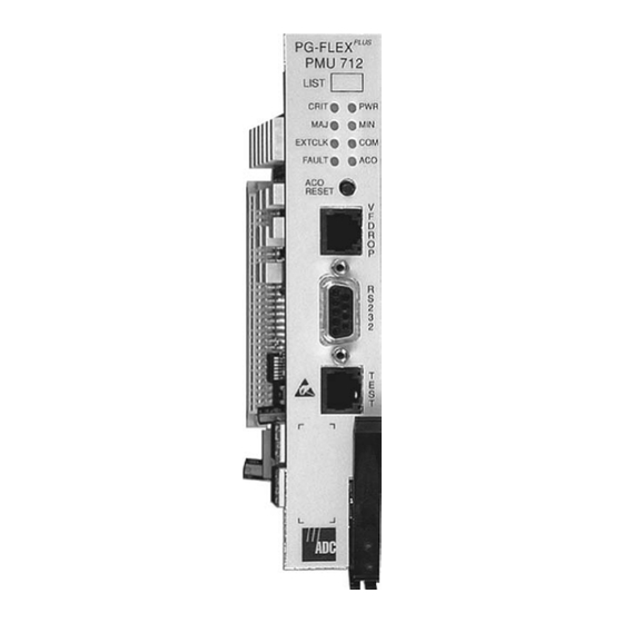
Page 23: Front Panel
SCP-PMU712-020-08H Overview RONT ANEL Figure 5 shows the PMU-712 front panel. The Status LEDs indicate different system states as described in Table 7, “LED Indicators,” on page Table 8, “LED Modes,” on page 12 describes the LED modes. The features of the front panel are: •... - Page 24 No composite clock signal. Green Multishelf management through Ethernet connection is active. Remote management is not active. FAULT Board failure. Return board to ADC. Board has not failed. Yellow ACO was operated. ACO button has not been operated. Table 8.
-
Page 25: Installation And Test
SCP-PMU712-020-08H Installation and Test NSTALLATION AND NSTALLING THE To install the PMU-712 card: Open the retaining latch at the front bottom of the card. Slide the PMU-712 into the card guides for the slot marked COMMON. Push the card back until it touches the backplane card-edge connector. Engage the retaining latch on the front edge of the shelf. -
Page 26: Initialization Sequence
Alarm screen (see “Provisioning, Performance Monitoring and Testing” on page 24). The PMU-712 and PG-Plus systems operate without provisioning. ADC recommends that, as a minimum, you change the password and set the date and time for the shelf. For instructions on this process, see the “Shelf Options Screen”... -
Page 27: Administration
SCP-PMU712-020-08H Administration DMINISTRATION To provision the PMU or other cards installed in the shelf using the craft interface, connect a VT-100 compatible terminal or a personal computer with VT-100 terminal emulation software to the RS-232 interface of the Plus PG-Flex Management Unit (PMU) or shelf backplane. -
Page 28: Front Panel Craft Port To Modem Connections
Administration SCP-PMU712-020-08H RONT ANEL RAFT ORT TO ODEM ONNECTIONS Using a cable that connects the Data Terminal Ready (DTR) signal will ensure automatic log off when the terminal is unplugged. When connecting the RS-232 port to a modem, a null modem cable should be used. Ensure that the modem’s Carrier Detect (CD) and DTR functions are enabled. -
Page 29: Backplane Craft Port To Modem Connections
SCP-PMU712-020-08H Administration ACKPLANE RAFT ORT TO ODEM ONNECTIONS The backplane DB-25 is a female connector wired as a Data Terminal Equipment (DTE) interface. Figure 9 shows the cable connections between the backplane connector and a DCE DB-25 connector. Figure 9. Backplane Craft Port to Modem Connections Refer to Table 9 to set up the VT-100 craft port connections. -
Page 30: Software Connection
Administration SCP-PMU712-020-08H Software Connection The PMU-712 supports all TELNET client application software complying with the (RFC854)-"The Telnet Protocol" standard to access the TL1 interface. Additionally, TELNET client applications providing full support for the VT-100 standard may be used to remotely access the Screens and Screens MultiShelf interfaces. Known VT-100 compliant TELNET client applications are: •... - Page 31 SCP-PMU712-020-08H Administration Table 10. Example of Isolated LAN Connection Subnet Gateway IP Default Default Route Entity IP Address Results Mask Address Route Mask PMU A 172.17.0.3 255.255.0.0 0.0.0.0 0.0.0.0 0.0.0.0 Defines that the PMU exists on the 172.17.xxx.xxx network and responds only to requests originating from this network.Thus, the following hosts may or may not communicate with the target PMU Host 1 172.17.20.9...
-
Page 32: Mslan Connection To Router/Bridge/Switch - Same Segment
Administration SCP-PMU712-020-08H MSLAN Connection to Router/Bridge/Switch - Same Segment By connecting the MSLAN to a router/bridge/switch, accessibility to the MSLAN expands to the virtual distance of the connected LAN, MAN or WAN (see Table 11 Figure 11). In this topography, clients attempting to connect by means of the TELNET protocol must have a configured IP Address and Subnet Mask matching that network defined by the target PMU. -
Page 33: Mslan Connection To Router/Bridge/Switch - Different Segment, Unrestricted Route
SCP-PMU712-020-08H Administration MSLAN Connection to Router/Bridge/Switch - Different Segment, Unrestricted Route In the set-up illustrated in Figure 12, clients attempting to connect through the TELNET protocol must configure the PMU to respond to packets not originating on the local segment (see Table 12, “Example of Connection to Router/Bridge/Switch - Different Segment, Unrestricted Route,”... -
Page 34: Example Of Connection To Router/Bridge/Switch - Different Segment, Unrestricted Route
Administration SCP-PMU712-020-08H Table 12. Example of Connection to Router/Bridge/Switch - Different Segment, Unrestricted Route Gateway IP Default Default Route Entity IP Address Subnet Mask Results Address Route Mask PMU A 172.17.0.3 255.255.0.0 0.0.0.0 0.0.0.0 0.0.0.0 Defines that the PMU exists on the 172.17.xxx.xxx network and responds only to requests originating from this network.Thus, the following gateways may or may not be accessible by the target PMU Case 1 172.17.20.9... -
Page 35: Mslan Connection To Router/Bridge/Switch - Different Segment, Restricted Route
SCP-PMU712-020-08H Administration MSLAN Connection to Router/Bridge/Switch - Different Segment, Restricted Route In the set-up shown in Table 13, clients attempting to connect by means of the TELNET protocol must configure the PMU to respond to packets not originating on the local segment but confine the accessibility of the MSLAN to a particular network (see “IP Information Screen”... -
Page 36: Provisioning, Performance Monitoring And Testing
TL1 commands, rather than the system screens, you will require the applicable TL1 command reference practice for the PMU, available in a PDF format for viewing, downloading, and printing at the ADC Technical Manuals web page at www.adc.com. -
Page 37: Logging On
If you select to manage the shelf through the TL1 terminal mode, refer to the applicable TL1 command reference practice for this information. You can download this document from the ADC Technical Manuals web page at www.adc.com. Entering the TL1 prompt chg-mode::screens will permanently change the interface to screens mode, while entering chg-dialog is for the current session only. - Page 38 • If the password has been changed and the new password is not known, contact ADC Technical Support while at the terminal (see “Technical Support” on page 77). They will provide a temporary password based on the Access Key number displayed on the Logon screen.
-
Page 39: Changing Modes
SCP-PMU712-020-08H Provisioning, Performance Monitoring and Testing The banner momentarily appears, and then the main menu bar of the PMU displays. Figure 16. Banner Screen Changing Modes When the terminal mode has been set to only TL1 mode, to change back to screens mode: type chg-mode::both;... -
Page 40: Pmu Main Menu
Provisioning, Performance Monitoring and Testing SCP-PMU712-020-08H PMU M The screens are identified at the top. The provisionable shelf ID string displays at the bottom center, the date displays at the lower left of the screen, and the time in 24 hour format displays at the lower right of the screen. Go to “Date and Time Screen”... -
Page 41: Navigational Methods
SCP-PMU712-020-08H Provisioning, Performance Monitoring and Testing Table 14. Navigational Methods Keypress Effect on Menu Effect on Screen Moves to submenu or screen selected. Invokes selected response to prompt. ENTER ← Moves left across Main menu. Moves the cursor to the left. CTRL Moves right across Main menu. -
Page 42: Shelf Summary
Provisioning, Performance Monitoring and Testing SCP-PMU712-020-08H MAIN Shelf Summary Composite Clocks Test Access Start TL1 Session Logout NETWORK MultiShelf Access Connection Summary Local Summary MUX 1 SELECT MUX 2 COLU 1 COLU 2 COLU 3 COLU 15 COLU 16 ALARMS Alarm Summary Alarm History Service Loss Alarm History... -
Page 43: Main Submenu
SCP-PMU712-020-08H Provisioning, Performance Monitoring and Testing UBMENU This screen provides access to information about the Shelf Summary, Composite Clocks and Test Access screens. You can also have the options to start a TL1 session, or log off the PMU screen session from this submenu. At the PMU main screen, select the MAIN option and press to view the submenu. -
Page 44: Shelf Summary Screen
Provisioning, Performance Monitoring and Testing SCP-PMU712-020-08H Shelf Summary Screen This screen details the types and positions of cards installed and displays existing alarms in the shelf. At the MAIN submenu, select the Shelf Summary option and press to view the screen. ENTER Figure 21. -
Page 45: Composite Clocks Screen
SCP-PMU712-020-08H Provisioning, Performance Monitoring and Testing Composite Clocks Screen The Composite Clocks screen displays the current status and conditions of the Composite Clocks. At the MAIN submenu, select the Composite Clocks option and press to view the screen. ENTER Figure 22. Composite Clocks Screen The time of the last switch is displayed at the bottom right of the screen. - Page 46 Provisioning, Performance Monitoring and Testing SCP-PMU712-020-08H Table 16. Composite Clocks Field Values Description Active CC The clock selected by the PMU to be used by the shelf. Condition of CC 1 Normal Composite Clock is considered valid. An active Loss of Signal alarm exists. Condition of CC 2 Normal Composite Clock is considered valid.
-
Page 47: Test Access Screen
SCP-PMU712-020-08H Provisioning, Performance Monitoring and Testing Test Access Screen This screen allows you to perform test access on channels for the units installed in the shelf. At the MAIN submenu, select the Test Access option and press to view the submenu. ENTER to the desired slot and press ENTER... - Page 48 Provisioning, Performance Monitoring and Testing SCP-PMU712-020-08H If you select a card that is not equipped, the following error message will display: Figure 25. Test Access Start Warning Screen Press to return to the PMU main menu. March 1, 2004 PMU-712 List 2...
-
Page 49: Start Tl1 Session
SCP-PMU712-020-08H Provisioning, Performance Monitoring and Testing Start TL1 Session This screen allows you to exit the screens and return to the TL1 command line. At the MAIN submenu, select the Start TL1 Session option and press to view the screen. ENTER Figure 26. -
Page 50: Logout Screen
Provisioning, Performance Monitoring and Testing SCP-PMU712-020-08H Logout Screen If you must leave your VT-100 terminal unattended, it is a good practice to log out until you are ready to resume work. This prevents unauthorized persons from inadvertently changing any of the system operating parameters. At the MAIN submenu, select the Logout option and press to view the screen. -
Page 51: Network Submenu
SCP-PMU712-020-08H ETWORK UBMENU This submenu allows you to view all available and connected PMUs existing on the 10Base-2 LAN. At the PMU main screen, select the NETWORK option and press to view the submenu. ENTER Select the desired option and press to view the screen. -
Page 52: Multishelf Access Screen
SCP-PMU712-020-08H MultiShelf Access Screen This screen allows you to view the multishelf access. This screen displays a list of all accessible PMUs existing on the 10Base-2 LAN. At the NETWORK submenu, select the MultiShelf Access option and press to view the screen. If the ENTER system does not have MultiShelf connections, an error message flashes at the bottom of the screen: Network Table Empty.** Hit <CR>... -
Page 53: Connection Summary Screen
SCP-PMU712-020-08H Connection Summary Screen This screen allows you to view all incoming MultiShelf connections (maximum of three). MultiShelf screens supports a series of outbound connections with up to 24 remote PMUs while maintaining up to three simultaneous inbound connections. At the NETWORK submenu, select the Connection Summary option and press to view the screen. -
Page 54: Local Summary Screen
SCP-PMU712-020-08H Local Summary Screen This screen allows you to view the MultiShelf Local Card Summary for the PMU, including card identification information, port session locations and states, and alarm activity. At the NETWORK submenu, select the Local Summary option and press to view the screen. -
Page 55: Select Submenu
SCP-PMU712-020-08H ELECT UBMENU This submenu allows you to select any of the cards installed in the COTS. At the PMU main screen, choose the SELECT option and press to view the submenu. ENTER Select the desired slot and press to access the card. ENTER Figure 34. - Page 56 SCP-PMU712-020-08H If you select an occupied slot, the main screen of the selected COLU or PMX displays: Figure 36. PMX Unit #1 Main Screen At this screen you can view alarms, configure parameters, and perform tasks on the selected card. Refer to the documentation for the unit installed in the selected slot for additional information.
-
Page 57: Alarms Submenu
SCP-PMU712-020-08H LARMS UBMENU This submenu gives you access to the summary and history of the alarms and relays. You can also activate the ACO alarm from one of the screens. At the PMU main screen, select the ALARMS option and press to view the submenu. -
Page 58: Alarm Summary Screen
SCP-PMU712-020-08H Alarm Summary Screen This screen displays the FDU-437 and FDU-439 alarmed events and the COTS alarm summary. The summary shows critical, major, or minor active alarms, and alarm history for each unit plugged into the COTS. At the ALARMS submenu, select the Alarm Summary option and press to view the screen. -
Page 59: Alarm History Screen
SCP-PMU712-020-08H Alarm History Screen This screen displays the history of all FDU-437 and FDU-439 alarmed events. At the ALARMS submenu, select the Alarm History option and press to view the screen. ENTER Figure 39. Alarm History Screen Current values shown: ACTIVE if an alarm exists OK if there is no alarm condition. -
Page 60: Service Loss Alarm History Screen
SCP-PMU712-020-08H Service Loss Alarm History Screen This screen displays the Service Loss Alarm history for all COLUs in the COTS. At the ALARMS submenu, select the Service Loss Alarm History option and press to view the screen. ENTER Figure 40. Service Loss Alarm History Screen At this screen you have the following options: •... -
Page 61: Environmental Alarm History Screen
SCP-PMU712-020-08H Environmental Alarm History Screen This screen displays the history of environmental alarmed events for the PMU. At the ALARMS submenu, select the Environmental Alarm History option and press to view the ENTER screen. Figure 41. Environmental Alarm History Screen At this screen you have the following options: •... -
Page 62: Relay Summary Screen
SCP-PMU712-020-08H Relay Summary Screen This screen displays the relay summary information of the system. At the ALARMS submenu, select the Relay Summary option and press to view the screen. ENTER Figure 42. Relay Summary Screen Current values shown: • if the relay is activated ACTIVE •... -
Page 63: Led Summary Screen
SCP-PMU712-020-08H LED Summary Screen This screen displays a summary of the LED activity. At the ALARMS submenu, select the LED Summary option and press to view the screen. ENTER Figure 43. LED Summary Screen Current values shown: • ON if the LED is lighted •... -
Page 64: Activate Aco Screen
SCP-PMU712-020-08H Activate ACO Screen This screen allows you to activate the Alarm Cutoff feature of the PMU. At the ALARMS submenu, select the Activate ACO option and press to view the screen. ENTER Figure 44. Activate ACO Screen At the prompt, you can: ACO WILL BE ACTIVATED. -
Page 65: Configuration Submenu
SCP-PMU712-020-08H ONFIGURATION UBMENU Using the screens available in this submenu, you can custom configure the Model Number. The configurable data on the Model Number includes the password, IP address, alarm types, date and time, terminal mode, and the COTS At the PMU main screen, select the CONFIG option and press to view the submenu. -
Page 66: Shelf Options Screen
SCP-PMU712-020-08H Shelf Options Screen The Shelf Options screen allows you to configure the optional features of the shelf to your preferences. At the CONFIG submenu, select Shelf Options and press to view the screen. ENTER Figure 47. Shelf Options Screen Press to select the desired field, then press the to toggle to the desired value for the switching... -
Page 67: Shelf Options Screen, Paged Forward
SCP-PMU712-020-08H Figure 48. Shelf Options Screen, Paged Forward – To enable or disable automatic provisioning of the PMU Options, press the press the SPACEBAR toggle to the desired value, or press a directional key to move to next option. See Table 18, “Shelf Options Configuration Fields,”... -
Page 68: Shelf Options Configuration Fields
SCP-PMU712-020-08H Table 18. Shelf Options Configuration Fields Options Value Description List 2 Default Composite Clock Nonrevertive. At power-up, the active CC NONREVERTIVE Switching Mode defaults to CC1. Switching occurs any time the active CC becomes invalid and the inactive CC is valid. After switching, the CC will not automatically revert back to CC1 when it becomes valid. - Page 69 SCP-PMU712-020-08H Table 18. Shelf Options Configuration Fields Options Value Description List 2 Default Shelf Alarm Relay STANDARD Alarm relay terminations on the STANDARD Setting COT shelf backplane support NOTE: This setting the following indications: is automatically changed to ENVIRONMENTAL System ID when the PMU is Critical - Visual plugged into a field...
-
Page 70: Ip Information Screen
SCP-PMU712-020-08H IP Information Screen This screen allows you to change the PMU’s IP address. To modify the configuration, see the following discussion. At the CONFIG submenu, select the IP Info option and press to view the screen. ENTER You can configure the IP settings following the rules outlined in Table Figure 49. -
Page 71: Password Screen
SCP-PMU712-020-08H Password Screen This screen allows you to set or change the system password. At the CONFIG submenu, select the Password option and press to view the screen. ENTER Figure 50. Password Screen To change the password: Enter the old password in the field, and press to gain access Enter Old Password And Press Return:... -
Page 72: Alarm Types Screen
SCP-PMU712-020-08H Alarm Types Screen The FDU-437 and FDU-439 detects and reports alarmed events specific to the FDU-437 and FDU-439, and alarms for all the units installed in the COTS. The notification type, such as Major, Minor, or Not Alarmed, is provisioned on the unit where the event is detected. - Page 73 SCP-PMU712-020-08H Table 20. Alarm Types Alarms Value Description List 2 Default CC1 Loss of Signal NA, NR, MN, MJ, CR Composite clock 1 signal is missing CC2 Loss of Signal NA, NR, MN, MJ, CR Composite clock 2 signal is missing Active Composite clock LOS NA, NR, MN, MJ, CR A loss of signal has been detected on the...
-
Page 74: Service Loss Alarm Types Screen
SCP-PMU712-020-08H Service Loss Alarm Types Screen All service Alarm types can be provisioned at this screen. At the CONFIG submenu, select the Service Loss Alarm Types option and press to view the screen. ENTER Figure 52. Service Loss Alarm Types Screen To change the Service Loss Alarm Types: Select the alarm type field, then press to toggle to the value desired. -
Page 75: Environmental Alarms Setup Screen
SCP-PMU712-020-08H Environmental Alarms Setup Screen The TR-08 data link alarm types can be provisioned at this screen for each environmental alarm. At the CONFIG submenu, select the Environmental Alarms Setup screen option and press to view ENTER the screen. Figure 53. Environmental Alarms Setup Screen To change the Environmental Alarms Setup: Select the TR-08 Data Link Alarm field for the desired Environmental Alarm, then press SPACEBAR... -
Page 76: Environmental Alarm Tr-08 Bit Positions
SCP-PMU712-020-08H Each environmental alarm can be sent via specific bit locations in the datalink. Refer to Table 22 for a list of possible alarm bit values. Refer to Table 23 for alarm defaults. Table 22. Environmental Alarm TR-08 Bit Positions Value Description NOT REPORTED... -
Page 77: Environmental Alarm Types Screen
SCP-PMU712-020-08H Environmental Alarm Types Screen At the CONFIG submenu, select the Environmental Alarm Types option and press to view the screen. ENTER Figure 54. Environmental Alarm Types Screen To change the Environmental Alarm Types: Select the type field for the desired Environmental Alarm, then press to toggle to the value SPACEBAR desired. -
Page 78: Date And Time Screen
SCP-PMU712-020-08H Date and Time Screen You can set the time zone and calendar date at this screen. All the screens show the default month, date, and year that comes with the system. At the CONFIG submenu, select the Date and Time option and press to view the screen. -
Page 79: Terminal Mode Screen
SCP-PMU712-020-08H Terminal Mode Screen The terminal mode allows the PMU terminals to act in a pure screen mode, a pure TL1 mode, or a hybrid of both modes. • In SCREENS mode, the terminals supply only screen sessions; thus you can not change to a TL1 session while in screens mode. -
Page 80: Set Factory Defaults Screen
SCP-PMU712-020-08H Set Factory Defaults Screen At this screen you can reset the system to the factory default values. At the CONFIG submenu, select the Set Factory Defaults option and press to view the screen. ENTER Figure 57. Set Factory Defaults Screen To reset all PMU values to the factory defaults: Type at the CONFIGURATION DATA WILL BE SET TO FACTORY DEFAULTS. -
Page 81: Software Download Submenu
SCP-PMU712-020-08H OFTWARE OWNLOAD UBMENU At the PMU main screen, select the CONFIG option and press to view the submenu. ENTER Select the desired option and press to view the screen. ENTER Figure 58. Software Download Submenu Press to return to the PMU main menu. PMU-712 List 2 March 1, 2004... -
Page 82: Start A Download Screen
SCP-PMU712-020-08H Start A Download Screen At the S/W DNLD submenu, select the Start A Download option and press to view the screen. ENTER The S/W DNLD menu has buttons representing the units that can be selected for software download. Plus PG-Flex microprocessor based units use flash memory to facilitate upgrading the stored software in the field. -
Page 83: Software Download Confirmation Screen
SCP-PMU712-020-08H Figure 60. Software Download Confirmation Screen Type at the COLU4 Chosen for Software Download. Please Confirm (Y/N)? prompt to continue. This screen shows that COLU-4 was selected for the target of the software download. An RT download may take up to several minutes to prepare for a software download. If the system was unable to prepare for the download, or if you chose an empty slot for the software download, an error message displays indicating a possible reason for the failure: Figure 61. -
Page 84: Download Retry
SCP-PMU712-020-08H If the system was able to prepare for download, a message informs you that the system is ready, and the appropriate steps to take: Figure 62. Software Download System Ready Screen Instruct the terminal emulator to begin an XMODEM upload. •... -
Page 85: Software Download With Modem
SCP-PMU712-020-08H If a card fails to download, you can continue to retry until a successful download is achieved. If a failure occurs on a FDU-437 and FDU-439 or COLU and no response is received to subsequent download attempts, remove and then reinsert the FDU-437 and FDU-439 or COLU into the COTS and retry the download. -
Page 86: Error Messages
SCP-PMU712-020-08H Error Messages Download error messages described below are shown in bold type, and are followed by a short description of the message. Software Download Command Timed Out - The FDU-437 and FDU-439 sent a command to the card that was to be downloaded, and did not receive a response from the card. -
Page 87: Information Submenu
SCP-PMU712-020-08H NFORMATION UBMENU The Information submenu provides technical information about the system and contact information for ADC. At the PMU main screen, select the INFO option and press to view the submenu. ENTER Select the desired option and press to view the screen. -
Page 88: Inventory Screen
PMU main menu. Help Screen The Help Screen provides information on using the FDU-437 and FDU-439 screens and menus and also lists the ADC Customer Support telephone number. At the INFO submenu, select the Help option and press to view the screen. -
Page 89: Product Support
ADC’s Return Material Authorization (RMA) Department. Call or write ADC’s RMA Department to ask for an RMA number and any additional instructions. Use the telephone number, fax number or email address listed below: •... - Page 90 Pack the equipment in a shipping carton. Write ADC’s address and the RMA Number you received from the RMA Department clearly on the outside of the carton. All shipments are to be returned prepaid. ADC will not accept any collect shipments.
-
Page 91: Fcc Classa Compliance
The FCC requires the user to be notified that any changes or modifications made to this device that are not expressly approved by ADC voids the user's warranty. All wiring external to the product(s) should follow the provisions of the current edition of the National Electrical Code. -
Page 92: Acronyms
Acronyms SCP-PMU712-020-08H CRONYMS Alarm Cut-Off CCLK Composite Clock Central Office COLU Central Office Line Unit COTS Central Office Terminal Shelf Critical Derived Data Link Digital Data Service Data Set Ready Data Terminal Ready Federal Communications Commission HDSL High-bit-rate Digital Subscriber Line IDLC Integrated Digital Loop Carrier ISDN... - Page 94 World Headquarters: ADC Telecommunications, Inc. PO Box 1101 Minneapolis, Minnesota USA 55440-1101 For Technical Assistance: 800.366.3891 ´,un¶3y¨ 1285783...
Need help?
Do you have a question about the PG-FLEXPLUS PMU-712 and is the answer not in the manual?
Questions and answers