Table of Contents

Related Manuals for ADC PG-Flex FLL-812


Summary of Contents for ADC PG-Flex FLL-812
- Page 1 PG-Flex 24 Channel Universal Central Office Line Unit Technical Practice FLL 812 LINE UNIT LIST SYNC LOOP 1 MARGIN SYNC LOOP 2 MARGIN TEST ALARM FAULT RS 232 Model List CLEI Code FLL-812 VACHDTNC~~ Section SCP-FLL812-011-01H...
- Page 3 Information furnished by ADC is believed to be accurate and reliable. In no event shall ADC be liable for any damages resulting from the loss of data, loss of use, or loss of profits and ADC further disclaims any and all liability for indirect, incidental, special, consequential or other similar damages.
-
Page 4: Using This Technical Practice
• Unpack each container and visually inspect the contents for signs of damage. If the equipment has been dam- aged in transit, immediately report the extent of damage to the transportation company and to ADC. Order replacement equipment, if necessary. -
Page 5: Table Of Contents
MAIN — System Summary ....................MAIN — Logout ......................... Performance Menu Options ....................PERFORMANCE — HDSL Summary ................PERFORMANCE — HDSL 24 Hour History ..............PERFORMANCE — HDSL 7 Day History ................ PERFORMANCE — ISDN Summary ................ADC Telecommunications, Inc. - Page 6 Information Menu Options ...................... 129 INFO — LU Inventory ......................130 INFO — COCU Inventory ....................131 INFO — RTCU Inventory ....................132 INFO — Doublers ......................133 INFO — Common Cards ....................134 INFO — Help ........................135 ADC Telecommunications, Inc.
- Page 7 March 13, 2003 SCP-FLL812-011-01H Appendix A ..........................139 Acronyms ..........................141 Product Support ........................143 Technical Support ......................143 Limited Warranty ....................... 143 Returns ..........................143 FCC Class A Compliance ....................... 144 Modifications ........................144 ADC Telecommunications, Inc.
- Page 8 SCP-FLL812-011-01H March 13, 2003 ADC Telecommunications, Inc.
- Page 9 Front Panel Craft Port to Modem Connections ............. 13 Figure 5. Backplane Craft Port to Terminal Connections Using a Null Modem Cable ..14 Figure 6. Backplane Craft Port to Modem Connections ............15 Figure 7. Terminal Menu and Display Structure ..............18 ADC Telecommunications, Inc.
- Page 10 SCP-FLL812-011-01H March 13, 2003 viii ADC Telecommunications, Inc.
- Page 11 Table 26. POTS Options ......................108 Table 27. Test Menu Options ....................118 Table 28. Metallic Access Menu Option Descriptions ............128 Table 29. Information Menu Options ..................129 Table 30. Fault Isolation and Troubleshooting ............... 136 ADC Telecommunications, Inc.
- Page 12 SCP-FLL812-011-01H March 13, 2003 ADC Telecommunications, Inc.
-
Page 13: Overview
Please refer to Appendix A on page 139 to facilitate proper system configuration. The Feature IMPORTANT Matrix identifies the major features in the CO and RT line units. The Compatibility Matrix provides CO and RT line unit compatibility information. ADC Telecommunications, Inc. -
Page 14: Functions And Features
• HDSL line transceivers and power supply • Front panel status indicators • Front panel craft terminal interface • Downloadable software for product maintenance • Eliminates the requirement for a metallic bypass pair (though supported when needed) for subscriber drop testing ADC Telecommunications, Inc. -
Page 15: Hdsl Transmission
00:05. A minimum of 20 mA is drawn through each conductor of HDSL (side 1 + side 2) during the time the sealing current feature is active. The current flow is ramped at a rate less than 20 mA/second to meet industry standard requirements for pulsed sealing current. ADC Telecommunications, Inc. -
Page 16: Subscriber Drop Testing
Refer to the FPI-829 technical practice for specific resistive signatures provided by the various models of the FPI-829. The FLL-812 can be configured to use a metallic bypass pair for subscriber drop testing in cases when MLT does not support TA-909 resistive signatures. ADC Telecommunications, Inc. -
Page 17: Specifications
Temperature ° F to +150° F ° C to +65° C Humidity 5% to 95% (non-condensing) Physical Height 5.5 in. (14.0 cm.) Width 2.0 in. (5.1 cm.) Depth 10.5 in. (26.7 cm.) Weight 2.0 lbs. (0.9 kg.) ADC Telecommunications, Inc. -
Page 18: Front Panel
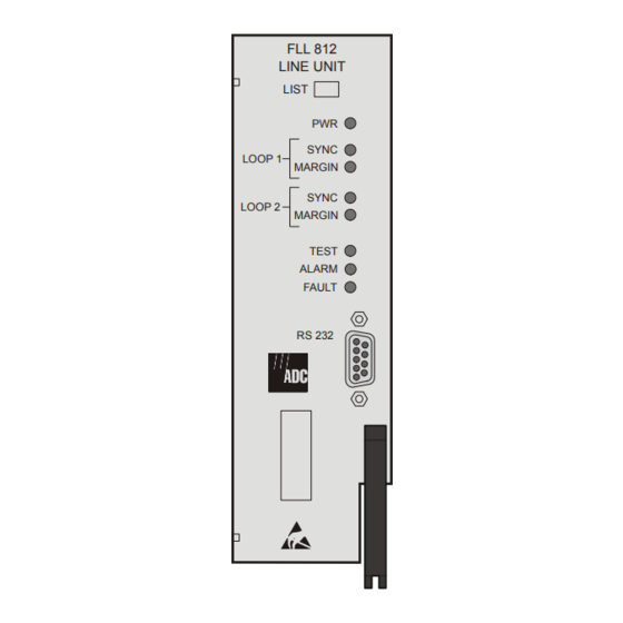
FLL 812 LINE UNIT LIST SYNC Loop 1 Status LOOP 1 MARGIN SYNC Loop 2 Status LOOP 2 MARGIN Test Indicator TEST ALARM Alarm Indicator FAULT Fault Indicator RS 232 RS-232 Maintenance Port Figure 2. FLL-812 Front Panel ADC Telecommunications, Inc. -
Page 19: Table 4. Fll-812 Front Panel Leds
(refer to Table 30 on page Flashing RT Line Unit alarm condition exist for troubleshooting No alarm conditions exist details) FAULT Fault in the COLU (refer to Table 30 on page No fault is detected for troubleshooting details) ADC Telecommunications, Inc. -
Page 20: Table 5. Fll-812 Diagnostic Indicators
Wait for download to complete and All other LEDs sequencing FLL-812 to re-start downward PWR LED On, Software download to the FRL-842 Wait for download to complete and All other LEDs sequencing connected to FLL-812 FLL-812 to re-start upward ADC Telecommunications, Inc. -
Page 21: Installation And Test
Install a FLL-812 Step Action Insert the FLL-812 into a vacant slot in the shelf that corresponds to the location of the wiring for the service being activated. Engage the retaining latch to hold the card in place. ADC Telecommunications, Inc. -
Page 22: Initialize And Power Up The Fll-812
• PWR LED flashes for approximately 12 seconds, then remains on • SYNC LEDs flash for approximately six seconds, then remains off • DSL Power Feed Short (PFS) alarm indicated in ALARMS — COLU System History on page 51 • FLL-812 waits one minute, then repeats step ADC Telecommunications, Inc. -
Page 23: Table 6. Fll-812 Led Status
It takes approximately two minutes before end-to-end synchronization is established with two doublers installed in the circuit. However, depending on the condition of the cable plant and length of the spans, it may take up to four minutes before synchronization is established. ADC Telecommunications, Inc. -
Page 24: Administration
RONT ANEL RAFT ORT TO ERMINAL ONNECTIONS Connections between the RS-232 craft port of the FLL-812 or FPI-829 and the craft terminal are shown in Figure Figure 3. Front Panel Craft Port to Terminal Connections ADC Telecommunications, Inc. -
Page 25: Front Panel Craft Port To Modem Connections
FLL-812 drops Data Set Ready (DSR) and the unit logs off after the modem drops CD. The following connections are required to make the modem work correctly (Figure Figure 4. Front Panel Craft Port to Modem Connections ADC Telecommunications, Inc. -
Page 26: Backplane Craft Port To Terminal Connections
Use a null modem cable to connect to a Data Terminal Equipment (DTE) device from the backplane connector. Figure 5 shows the wiring for the required null modem cable to a DB-9 and a DB-25 connector. Figure 5. Backplane Craft Port to Terminal Connections Using a Null Modem Cable ADC Telecommunications, Inc. -
Page 27: Backplane Craft Port To Modem Connections
– 2400 – 4800 – 9600 – 38400 • FPI-829: – 1200 – 2400 – 4800 – 9600 – 14400 – 19200 – 28800 – 38400 – 57600 Asynchronous Data Bits Communication Parity None None Parameters Stop Bits ADC Telecommunications, Inc. -
Page 28: Table 8. Modem Settings
SCP-FLL812-011-01H March 13, 2003 Table 8. Modem Settings Control Setting Supported Hardware Flow Control Software Flow XON/XOFF Enabled Control Baud Rate 1200 2400 4800 9600 19200 38400 Asynchronous Data Bits Communication Parity None Parameters Stop Bits ADC Telecommunications, Inc. -
Page 29: Navigational Methods
Selects an underlined or highlighted menu item A screen entry is made keys Some screens illustrated in this document may be slightly different than what may appear on the craft interface terminal. These differences are related to individual software installations. ADC Telecommunications, Inc. -
Page 30: Testing, Configuration, And Maintenance
Channel Unit Alarm Types POTS Options LS/GS Options Set Factory Defaults Channel Configuration Test Subscriber Drop Test Subscriber Bypass Metallic Access Information LU Inventory COLU Inventory RTCU Inventory Doublers Common Cards Help Figure 7. Terminal Menu and Display Structure ADC Telecommunications, Inc. -
Page 31: Log On Directly Through The Fll-812
This screen logs the user into the system directly through the FLL-812. The factory-default password is password#1. If the password has been changed and the new password is not known, contact ADC Technical Support while at the terminal. Technical Support will provide a temporary password based on the Access Key number displayed on the Logon screen. - Page 32 March 13, 2003 Log On Directly Through the FLL-812 (Continued) Step Action Type the Password, then press . After a successful login, the PG-Flex banner screen appears for ENTER a few seconds. Then, the Main Menu screen appears. ADC Telecommunications, Inc.
- Page 33 March 13, 2003 SCP-FLL812-011-01H Log On Directly Through the FLL-812 (Continued) Step Action After 15 minutes of inactivity, the following menu appears. Press . The Flex Login screen reappears. Repeat Step 1 Step 3 to log in again. ADC Telecommunications, Inc.
-
Page 34: Log On The Fll-812 Through The Fpi-829
This screen logs the user into the FLL-812 by going through the FPI-829. The factory-default password is password#1. If the password has been changed and the new password is not known, contact ADC Technical Support while at the terminal. Technical Support will provide a temporary password based on the Access Key number displayed on the Logon screen. - Page 35 Log On The FLL-812 Through the FPI-829 (Continued) Step Action Type the Password, then press . After a successful login, the PG-Flex banner screen appears for ENTER a few seconds. Then, the FPI-829 Main Menu screen appears. ADC Telecommunications, Inc.
- Page 36 SCP-FLL812-011-01H March 13, 2003 Log On The FLL-812 Through the FPI-829 (Continued) Step Action At the Main Menu, choose SELECT. Press to choose COLU (COLU 1-4, depending on your system ↓ configuration). The FLL-812 Main Menu appears. ADC Telecommunications, Inc.
- Page 37 SCP-FLL812-011-01H Log On The FLL-812 Through the FPI-829 (Continued) Step Action After 15 minutes of inactivity, the following menu appears. Press . The Flex Login screen reappears. Repeat Step Step 3 Step 4 to log in again. ADC Telecommunications, Inc.
-
Page 38: Main Menu Options
System Summary System status (spans, services, Display Channel Status Y or N channel status for each span and service) Logout Log out of the current PG-Flex Current Session will be Logged Y or N session Out. Continue (Y/N)?: ADC Telecommunications, Inc. -
Page 39: Main - System Summary
Table 11 on page 29 for System Status information. MAIN — System Summary Step Action At the Main Menu screen, select MAIN. Press to choose System Summary. The following screen ↓ appears. Press . The following screen appears. ENTER ADC Telecommunications, Inc. - Page 40 SCP-FLL812-011-01H March 13, 2003 MAIN — System Summary (Continued) Step Action To display channel status, press . The following screen appears. Press . The Main Menu screen reappears. ADC Telecommunications, Inc.
-
Page 41: Table 11. System Status
Voice path through the system is intact, No CO battery detected (OPEN at CO, IDLE at RT) RING Line is ringing RINGGND Ring ground detected at the RT TEST Testing being done on line TKCOND Forced line condition RBAT Reverse battery ADC Telecommunications, Inc. -
Page 42: Main - Logout
This prevents unauthorized persons from inadvertently changing any of your operating parameters and causing a possible loss of service. At the Main Menu screen, select MAIN. Press to choose Logout. The following screen appears. ↓ Press . The following screen appears. ENTER ADC Telecommunications, Inc. - Page 43 March 13, 2003 SCP-FLL812-011-01H MAIN — Logout (Continued) Step Action Press . The PG-Flex Login screen appears. ADC Telecommunications, Inc.
-
Page 44: Performance Menu Options
The Performance Menu provides access to HDSL and ISDN status (if ISDN is installed) and performance monitoring information. Refer to Table 12 on page 33 for sub-menu options and descriptions, parameters and valid values. ISDN menu selections are only present if ISDN is installed the system. ADC Telecommunications, Inc. -
Page 45: Table 12. Performance Menu Options
ISDN 7 Hour History View the 7 hour ISDN ES history • Clear ISDN PM Counts • Y or N info for this channel (Y)? • ISDN PM Counts will be • Y or N cleared. Continue (Y/N)? ADC Telecommunications, Inc. -
Page 46: Performance - Hdsl Summary
↓ screen appears. Press . The following screen appears. ENTER The following actions can be taken: a. To clear the minimum and maximum margins, press and continue with this procedure. b. To exit the HDSL Summary, press ADC Telecommunications, Inc. - Page 47 • minimum and maximum margins are set to the current margins • time and date that the margins were last set are updated b. To retain the existing minimum and maximum margins, press Press . The Main Menu screen reappears. ADC Telecommunications, Inc.
-
Page 48: Table 13. Hdsl Summary
• HDSLA INSRTN LOSS Loss on the HDSL A/B link • HDSLB INSRTN LOSS * The system works correctly with loop and/or tip and ring reversals. However, alarms are generated and fault isolation may be difficult. ADC Telecommunications, Inc. -
Page 49: Performance - Hdsl 24 Hour History
Data is saved in the history register for this interval • PAR (Partial): Data is being collected for this interval • UNA (Unavailable): Data has not been collected for this interval or has been reset during a previous time interval ADC Telecommunications, Inc. - Page 50 If there is an active 15-minute ES or UAS alarm, this alarm becomes inactive when the 24-hour performance history is cleared and reactivates once the threshold has been crossed. • To retain the existing HDSL 24 Hour History, press ADC Telecommunications, Inc.
- Page 51 March 13, 2003 SCP-FLL812-011-01H PERFORMANCE — HDSL 24 Hour History (Continued) Step Action Press . The Main Menu screen reappears. ADC Telecommunications, Inc.
-
Page 52: Performance - Hdsl 7 Day History
Data is saved in the history register for this interval • PAR (Partial): Data is being collected for this interval • UNA (Unavailable): Data has not been collected for this interval or has been reset during a previous time interval ADC Telecommunications, Inc. - Page 53 If there is an active 1-day ES or UAS alarm, this alarm becomes inactive when the 24-hour performance history is cleared and reactivates once the threshold has been crossed. • To retain the existing HDSL 7 Day History, press Press . The Main Menu screen reappears. ADC Telecommunications, Inc.
-
Page 54: Performance - Isdn Summary
Action At the Main Menu screen, select PERFORMANCE. Press to choose ISDN Summary. The following ↓ screen appears. Press . The following screen appears. ENTER To view the ISDN performance data, select the ISDN channel, then press ADC Telecommunications, Inc. - Page 55 Errors in the Customer column indicate errors in transmission from the Network (ISDN switch) to the Customer. Errors in the Network column indicate errors in transmission from the Customer to the Network. d. To retain the existing ISDN performance data, press Press . The Main Menu screen reappears. ADC Telecommunications, Inc.
-
Page 56: Performance - Isdn 7 Hour History
At the Main Menu screen, select PERFORMANCE. Press to choose ISDN 7 Hour History. The ↓ following screen appears. Press . The following screen appears.. ENTER To view ISDN 7 Hour ES history, select an ISDN channel unit, then press ENTER ADC Telecommunications, Inc. - Page 57 Errors in the Customer column indicate errors in transmission from the Network (ISDN switch) to the Customer. Errors in the Network column indicate errors in transmission from the Customer to the Network. d. To retain the existing performance data counts, press Press . The Main Menu screen reappears. ADC Telecommunications, Inc.
-
Page 58: Alarm Menu Options
The Alarm Menu provides access to the alarm status and system related alarm events. Refer to Table 14 on page 47 for sub-menu options and descriptions, parameters and valid values. ISDN menu selections are only present if ISDN is installed the system. ADC Telecommunications, Inc. -
Page 59: Table 14. Alarm Menu Options
CU History View the channel unit CU Alarm History will be cleared. Y or N alarm history Continue (Y/N)? COLU Faults View COLU faults detected by the unit RTLU Faults View RTLU faults detected by the unit ADC Telecommunications, Inc. -
Page 60: Alarms - Alarms Summary
• MAJOR Major alarm is present • MINOR Minor alarm is present • NOT ALARMED Condition is active, but has no severity • NOT REPORTED Condition not reported by system Alarm States: • * Designates active alarm ADC Telecommunications, Inc. - Page 61 ← → • SYSTEM ALARMS – COLU or RTLU • HDSL ALARMS – SPAN1, SPAN 2, or SPAN3 • CU ALARMS – COCU or RTCU • ISDN ALARMS – COLU or RTLU Then press ENTER ADC Telecommunications, Inc.
- Page 62 • all alarm history counts are set to zero • time and date that the registers were last cleared are updated f. To retain the existing summary of active alarms, press Press . The Main Menu screen reappears. ADC Telecommunications, Inc.
-
Page 63: Alarms - Colu System History
The status OK displays in the Current column when the alarm is not present. The status Active displays when an alarm is present (see Table 18 on page 84 for CO Alarms). A description of the Alarm types reported is provided in Table 17 on page ADC Telecommunications, Inc. - Page 64 If there is an active alarm, the count is set to 1 and the value in the LAST date and time field is set to the FIRST date and time field. • To retain the existing COLU alarm history, press ADC Telecommunications, Inc.
- Page 65 March 13, 2003 SCP-FLL812-011-01H ALARMS — COLU System History (Continued) Step Action Press . The Main Menu screen reappears. ADC Telecommunications, Inc.
-
Page 66: Alarms - Rtlu System History
The status OK displays in the Current column when the alarm is not present. The status Active displays when an alarm is present (see Table 19 on page 87 for RTLU Alarms). A description of the Alarm types reported is provided in Table 17 on page ADC Telecommunications, Inc. - Page 67 If there is an active alarm, the count is set to 1 and the value in the LAST date and time field is set to the FIRST date and time field. • To retain the existing RTLU alarm history, press ADC Telecommunications, Inc.
- Page 68 SCP-FLL812-011-01H March 13, 2003 ALARMS — RTLU System History (Continued) Step Action Press . The Main Menu screen reappears. ADC Telecommunications, Inc.
-
Page 69: Alarms - Hdsl History
The status OK displays in the Current column when the alarm is not present. The status Active displays when an alarm is present (see Table 21 on page 93 for HDSL Alarms). A description of the Alarm types reported is provided in Table 17 on page ADC Telecommunications, Inc. - Page 70 If there is an active alarm, the count is set to 1 and the value in the LAST date and time field is set to the FIRST date and time field. • To retain the existing HDSL alarm history, press ADC Telecommunications, Inc.
- Page 71 March 13, 2003 SCP-FLL812-011-01H ALARMS — HDSL History (Continued) Step Action Press . The Main Menu screen reappears. ADC Telecommunications, Inc.
-
Page 72: Alarms - Isdn History
ALARMS — ISDN History Step Action At the Main Menu screen, select ALARMS. ress to choose ISDN History. The following screen ↓ appears. Press . The following screen appears. ENTER ADC Telecommunications, Inc. - Page 73 The status OK displays in the Current column when the alarm is not present. The status Active displays when an alarm is present. A description of the Alarm types reported is provided in Table 17 on page ADC Telecommunications, Inc.
- Page 74 If there is an active alarm, the count is set to 1 and the value in the LAST date and time field is set to the FIRST date and time field. • To retain the existing ISDN alarm history, press ADC Telecommunications, Inc.
- Page 75 March 13, 2003 SCP-FLL812-011-01H ALARMS — ISDN History (Continued) Step Action Press . The Main Menu screen reappears. ADC Telecommunications, Inc.
-
Page 76: Alarms - Cu History
The status OK displays in the Current column when the alarm is not present. The status Active displays when an alarm is present (see Table 25 on page 105 for Channel Unit Alarms). A description of the Alarm types reported is provided in Table 17 on page ADC Telecommunications, Inc. - Page 77 If there is an active alarm, the count is set to 1 and the value in the LAST date and time field is set to the FIRST date and time field. • To retain the existing CU alarm history, press Press . The Main Menu screen reappears. ADC Telecommunications, Inc.
-
Page 78: Alarms - Colu Faults
If there are no faults detected, then the COLU Faults screen displays the message NO FAULTS ON COT LINE UNIT. If there is a fault detected, a descriptive message appears. Press . The Main Menu screen reappears. ADC Telecommunications, Inc. -
Page 79: Alarms - Rtlu Faults
If there are no faults detected, then the RT Faults screen displays the message NO FAULTS ON RT LINE UNIT. If there is a fault detected, a descriptive message appears. Press . The Main Menu screen reappears. ADC Telecommunications, Inc. -
Page 80: Configuration Menu Options
• Day • 1 – 31 • Year • 2002 (accepts any 4-number year on or after 1970) • Hour • 00 – 24 • Minute • 0 – 59 • Seconds • 0 – 59 ADC Telecommunications, Inc. - Page 81 (See Table 22 on page 96 for ISDN Options) ISDN Alarm Provision ISDN ISDN Alarm Thresholds will be Y or N Thresholds alarm thresholds changed. Continue (Y/N)? (See Table 23 on page 99 for ISDN Alarm Thresholds) ADC Telecommunications, Inc.
- Page 82 Changed. Continue to be set as (Y/N)? enabled or • All Channel will be Enabled. • Y or N disabled Continue (Y/N)? • All Channel will be Disabled. Continue (Y/N)? • Y or N ADC Telecommunications, Inc.
-
Page 83: Config - Password
This screen allows you to change the Password for security reasons. Refer to Table 15 on page 68 for valid values. CONFIG — Password Step Action At the Main Menu screen, select CONFIG. Press to choose Password. The following screen ↓ appears. Press . The following screen appears. ENTER ADC Telecommunications, Inc. - Page 84 Enter the current (old) Password (System Default is password#1). For security reasons, the system echoes the password with *. Press . The following screen appears. ENTER Enter the new Password. Press . The following screen appears. ENTER Enter the new Password again. Press . The following screen appears. ENTER ADC Telecommunications, Inc.
- Page 85 From The Password will be permanently changed. Continue (Y/N)? prompt, the following actions can be taken: • To accept the new password, press • To retain the existing password, press Press . The Main Menu screen reappears. ADC Telecommunications, Inc.
-
Page 86: Config - Date And Time
SPACEBAR appropriate month. b. To change the rest of the fields (Day, Year, Hour, Minute, Second), press to reach the field to ↓ ↑ be changed. Then type the appropriate numbers on the keypad for each field. ADC Telecommunications, Inc. - Page 87 To go back to the Main Menu, select the BACK TO MAIN SCREEN button, then press ENTER d. To accept the date only, select the ACCEPT DATE ONLY button, then press ENTER Press . The Main Menu screen reappears. ADC Telecommunications, Inc.
-
Page 88: Config - System Options
Table 16 on page 79 for system options CONFIG — System Options Step Action At the Main Menu screen, select CONFIG. Press to choose System Options. The following screen ↓ appears. Press . The following screen appears. ENTER ADC Telecommunications, Inc. - Page 89 • To save the shelf options, press . The following events occur: – all current values are set to desired values • To retain the existing shelf options on the Shelf Options screen, press ADC Telecommunications, Inc.
- Page 90 SCP-FLL812-011-01H March 13, 2003 CONFIG — System Options (Continued) Step Action Press . The Main Menu screen reappears. ADC Telecommunications, Inc.
-
Page 91: Table 16. System Options
Termination Timeout – Metallic Access is Metallic Access Termination Timeout – Metallic Access times out after 30 minutes Termination Timeout – Metallic Access times out after 60 minutes Termination Timeout – Metallic Access times out after 120 minutes ADC Telecommunications, Inc. - Page 92 ENABLED Sealing Current load is automatically applied for a period of 15-20 seconds, once every 24 hours at the system clock time of 00:05 * RT SEALING CURRENT option is displayed only on a locally powered system. ADC Telecommunications, Inc.
-
Page 93: Config - Colu System Alarm Type
Alarm types reported. CONFIG — COLU System Alarm Type Step Action At the Main Menu screen, select CONFIG. Press to choose COLU System Alarm Types. The ↓ following screen appears. Press . The following screen appears. ENTER ADC Telecommunications, Inc. - Page 94 • To save the COLU alarm type changes, press . The following events occur: – all current values are set to desired values • To retain the existing COLU alarm types, press Press . The Main Menu screen reappears. ADC Telecommunications, Inc.
-
Page 95: Table 17. Alarm Types Reported
March 13, 2003 SCP-FLL812-011-01H Table 17. Alarm Types Reported Alarm LED Main Shelf Settings Reported Summary History Updated CR – Critical MJ – Major MN – Minor NA – Not Alarmed NR – Not Reported ADC Telecommunications, Inc. -
Page 96: Table 18. Co Alarms
CR, MJ, MN, NA, NR Temperature at RTLU is too low HIGH TEMPERATURE CR, MJ, MN, NA, NR Temperature at RTLU is too high EEPROM FAILURE CR, MJ, MN, NA, NR A checksum error has been detected on COLUs EEPROM data ADC Telecommunications, Inc. -
Page 97: Config - Rtlu System Alarm Types
Alarm types reported. CONFIG — RTLU System Alarm Types Step Action At the Main Menu screen, select CONFIG. Press to choose RTLU System Alarm Types. The ↓ following screen appears. Press . The following screen appears. ENTER ADC Telecommunications, Inc. - Page 98 • To save the RTLU alarm type changes, press . The following events occur: – all current values are set to desired values • To retain the existing RTLU alarm types, press Press . The Main Menu screen reappears. ADC Telecommunications, Inc.
-
Page 99: Table 19. Rtlu Alarms
CR, MJ, MN, NA, NR RT External 4 Alarm reported RT FAN FAILURE CR, MJ, MN, NA, NR RT Fan Failure reported * HDSL INPUT VOLTAGE option is displayed, set and cleared only on a line-powered system. ADC Telecommunications, Inc. -
Page 100: Config - Hdsl Alarm Thresholds
HDSL Alarm Threshold fields, values, descriptions and default settings. CONFIG — HDSL Alarm Thresholds Step Action At the Main Menu screen, select CONFIG. Press to choose HDSL Alarm Thresholds. The following ↓ screen appears. Press . The following screen appears. ENTER ADC Telecommunications, Inc. - Page 101 • To save the HDSL Alarm Threshold changes, press . The following events occur: – all current values are set to desired values • To retain the existing HDSL Alarm Thresholds, press Press . The Main Menu screen reappears. ADC Telecommunications, Inc.
-
Page 102: Table 20. Hdsl Alarm Thresholds
HDSL UAS-24 hour alarm is generated if UAS counts become equal to or greater than this threshold. HDSL LOW MARGIN 0 to 15 HDSL Low Margin alarm is generated if margin drops equal to or less than this threshold. ADC Telecommunications, Inc. -
Page 103: Config - Hdsl Alarm Types
Type fields, values, descriptions and default settings. CONFIG — HDSL Alarm Types Step Action At the Main Menu screen, select CONFIG. Press to choose HDSL Alarm Types. The following ↓ screen appears. Press . The following screen appears. ENTER ADC Telecommunications, Inc. - Page 104 • To save the HDSL Alarm Types changes, press . The following events occur: – all current values are set to desired values • To retain the existing HDSL Alarm Types, press Press . The Main Menu screen reappears. ADC Telecommunications, Inc.
-
Page 105: Table 21. Hdsl Alarm Types
HDSL LOOP REVERSAL CR, MJ, MN, NA, NR HDSL loops A and B are reversed on the span HDSL TIP-RING REVERSAL CR, MJ, MN, NA, NR HDSL tip-ring of the HDSL A/B loop is reversed on the span ADC Telecommunications, Inc. -
Page 106: Config - Isdn Options
ISDN Option fields, values, descriptions and default settings. CONFIG — ISDN Options Step Action At the Main Menu screen, select CONFIG. Press to choose ISDN Options. The following screen ↓ appears. Press . The following screen appears. ENTER ADC Telecommunications, Inc. - Page 107 • To save the ISDN Option changes, press . The following events occur: – all current values are set to desired values • To retain the existing ISDN Options, press Press . The Main Menu screen reappears. ADC Telecommunications, Inc.
-
Page 108: Table 22. Isdn Options
PM Clock Source field MANUAL Clock source is determined by PM Clock Source field PM Clock Source PG-FLEX Clock source is determined by PG-Flex PG-FLEX (Manual Mode) system clock ISDN SWITCH Clock source is determined by ISDN clock ADC Telecommunications, Inc. -
Page 109: Config - Isdn Alarm Thresholds
ISDN Alarm Threshold fields, values, descriptions and default settings. CONFIG — ISDN Alarm Thresholds Step Action At the Main Menu screen, select CONFIG. Press to choose ISDN Alarm Thresholds. The following ↓ screen appears. Press . The following screen appears. ENTER ADC Telecommunications, Inc. - Page 110 • To save the ISDN Alarm Threshold changes, press . The following events occur: – all current values are set to desired values • To retain the existing ISDN Alarm Thresholds, press Press . The Main Menu screen reappears. ADC Telecommunications, Inc.
-
Page 111: Table 23. Isdn Alarm Thresholds
1 to 127. DAILY SES 0 to 2047 ISDN daily SES alarm is generated if the accumulated daily SES count at the COLU/RTLU reaches or exceeds this threshold. The range of values is from 1 to 2047. ADC Telecommunications, Inc. -
Page 112: Config - Isdn Alarm Types
CONFIG — ISDN Alarm Types Step Action At the Main Menu screen, select CONFIG. Press to choose ISDN Alarm Types. The following screen ↓ appears. Press . The following screen appears. ENTER ADC Telecommunications, Inc. - Page 113 • To save the ISDN Alarm Type changes, press . The following events occur: – all current values are set to desired values • To retain the existing ISDN Alarm Types, press Press . The Main Menu screen reappears. ADC Telecommunications, Inc.
-
Page 114: Table 24. Isdn Alarm Types
D+ Loss of Frame CR, MJ, MN, NA, NR Generated if the ISDN m-channel framing pattern has been lost on the HDSL link D+ Loss of Signal CR, MJ, MN, NA, NR Generated if the ISDN m-channel loses synchronization ADC Telecommunications, Inc. -
Page 115: Config - Channel Unit Alarm Types
Channel Unit Alarm Type fields, values, descriptions and default settings. CONFIG — Channel Unit Alarm Types Step Action At the Main Menu screen, select CONFIG. Press to choose Channel Unit Alarm Types. The ↓ following screen appears. Press . The following screen appears. ENTER ADC Telecommunications, Inc. - Page 116 • To save the Channel Unit Alarm Type changes, press . The following events occur: – all current values are set to desired values • To retain the existing Channel Unit Alarm Types, press Press . The Main Menu screen reappears. ADC Telecommunications, Inc.
-
Page 117: Table 25. Channel Unit Alarms
Associated CU must be replaced to restore ringing functionality. If RTCU Ring Buffer Failure alarms are declared for all installed POTS Cards, the probable cause of failure is a faulty ring generator. The RTLU will need to be replaced. ADC Telecommunications, Inc. -
Page 118: Config - Pots Options
POTS Option fields, values, descriptions and default settings. CONFIG — POTS Options Step Action At the Main Menu screen, select CONFIG. Press to choose POTS Options. The following screen ↓ appears. Press . The following screen appears. ENTER ADC Telecommunications, Inc. - Page 119 • To save the POTS Option changes, press . The following events occur: – all current values are set to desired values • To retain the existing POTS Options, press Press . The Main Menu screen reappears. ADC Telecommunications, Inc.
-
Page 120: Table 26. Pots Options
All POTS circuits support shorter 430 ohm subscriber LONG drops and results in slightly reduced power consumption from the CO battery. LONG All POTS circuits support standard length 530 ohm subscriber drops. The power consumption from the CO battery matches the published specifications. ADC Telecommunications, Inc. -
Page 121: Config - Ls/Gs Options
This screen shows the Loop Start and Ground Start configuration. CONFIG — LS/GS Options Step Action At the Main Menu screen, select CONFIG. Press to choose LS/GS Options. The following screen ↓ appears. Press . The following screen appears. ENTER ADC Telecommunications, Inc. - Page 122 • To save the LS/GS Option changes, press . The following events occur: – all current values are set to desired values Only POTS channel units indicate LS/GS. ISDN channel units always display N/A. • To retain the existing POTS Options, press ADC Telecommunications, Inc.
- Page 123 March 13, 2003 SCP-FLL812-011-01H CONFIG — LS/GS Options (Continued) Step Action To view the Help Screen, select the HELP SCREEN button, then press . The Help Screen ENTER appears. Press . The Main Menu screen reappears. ADC Telecommunications, Inc.
-
Page 124: Config - Set Factory Defaults
Action At the Main Menu screen, select CONFIG. Press to choose Set Factory Defaults. The following ↓ screen appears. Press . The following screen appears. ENTER Setting to Factory Defaults may cause a loss of service. CAUTION ADC Telecommunications, Inc. - Page 125 • To save the Factory Default changes, press . The following events occur: – all current values are reset to the factory default values • To retain the existing configuration data, press Press . The Main Menu screen reappears. ADC Telecommunications, Inc.
-
Page 126: Config - Channel Configuration
RTCU) is removed, replaced or reinserted, the channel configuration is automatically preserved. CONFIG — Channel Configuration Step Action At the Main Menu screen, select CONFIG. Press to choose Channel Configuration. The following ↓ screen appears. Press . The following screen appears. ENTER ADC Telecommunications, Inc. - Page 127 From the CHANNEL CONFIGURATION WILL BE CHANGED. CONTINUE (Y/N)? prompt, the following actions can be taken: • To save the Channel Configuration changes, press . The following events occur: – all current values are set to desired values • To retain the existing configuration data, press ADC Telecommunications, Inc.
- Page 128 SCP-FLL812-011-01H March 13, 2003 CONFIG — Channel Configuration (Continued) Step Action To view the Help Screen, select the HELP button, then press . The Help screen appears. ENTER Press . The Main Menu screen reappears. ADC Telecommunications, Inc.
-
Page 129: Test Menu Options
If you attempting to run a second test when one test is already in progress, a flashing warning message appears. Wait a few minutes, then try to run the test again. ADC Telecommunications, Inc. -
Page 130: Table 27. Test Menu Options
Progress on Test Circuit will be COT Looking Out Terminated. Continue with Test (Y/ RT Looking Out N)?: • **POTS (CU#, CH#) Test in RT Looking In • S Progress** Hit ‘S’ to Stop the Test RT Bridging ADC Telecommunications, Inc. -
Page 131: Test - Subscriber Drop Test
The remaining lines on the PG-Flex system remain in service. TEST — Subscriber Drop Test Step Action At the Main Menu screen, select TEST. Press to choose Subscriber Drop Test. The following ↓ screen appears. Press . The following screen appears. ENTER ADC Telecommunications, Inc. - Page 132 • To start the test, press If you decide to stop the test, press to stop the test. Then press and the Main Menu screen reappears. • To abort the test, press . Then press and the Main Menu reappears. ADC Telecommunications, Inc.
- Page 133 Condition, and Test Status results is displayed. Tests are performed in the order of display. If a test fails, the remaining tests are not performed (as per TA-909). It takes approximately seven to eight seconds for all tests to complete. Press . The Main Menu screen reappears. ADC Telecommunications, Inc.
-
Page 134: Test - Subscriber Bypass
PG-Flex carrier transport. The bypass pair must be present for proper operation of this test configuration. TEST — Subscriber Bypass Step Action At the Main Menu screen, select TEST. Press to choose Subscriber Bypass. The following screen ↓ appears. Press . The following screen appears. ENTER ADC Telecommunications, Inc. - Page 135 Then press and the Main Menu screen reappears. • To abort the test, press . Then press and the Main Menu reappears. Upon completion of the test, press . Then press and the Main Menu reappears. ADC Telecommunications, Inc.
-
Page 136: Test - Metallic Access
RT test configurations. TEST — Metallic Access Step Action At the Main Menu screen, select TEST. Press to choose Metallic Access. The following screen ↓ appears. Press . The following screen appears. ENTER ADC Telecommunications, Inc. - Page 137 TEST — Metallic Access (Continued) Step Action All of the tests on this screen are implemented the same way; therefore, only one example is being shown. COT Bridging To run COT Bridging test, select the COT Bridging field. Press ENTER ADC Telecommunications, Inc.
- Page 138 • To start the test, press If you decide to stop the test, press to stop the test. Then press and the Main Menu screen reappears. • To abort the test, press . Then press and the Main Menu appears. ADC Telecommunications, Inc.
- Page 139 March 13, 2003 SCP-FLL812-011-01H TEST — Metallic Access (Continued) Step Action Upon completion of the test, press Then press and the Main Menu appears. ADC Telecommunications, Inc.
-
Page 140: Table 28. Metallic Access Menu Option Descriptions
Provides a connection to the subscriber drop with the RT channel unit disconnected (Metallic bypass pair required). RT - Bridging Monitors the connection between the RT channel unit and the subscriber terminal equipment (Metallic bypass pair required). ADC Telecommunications, Inc. -
Page 141: Information Menu Options
Displays product identification information, manufacturing data, software versions and the hardware revisions for Doublers (DB1, DB2) Common Cards Displays product identification information, manufacturing data, software versions and the hardware revisions for Common Cards (Alarm). Help Provides information on using the system screens and menus ADC Telecommunications, Inc. -
Page 142: Info - Lu Inventory
COLU and RTLU. Step Action At the Main Menu screen, select INFO. Press to choose Line Unit Inventory. The following screen ↓ appears. Press . The following screen appears. ENTER Press . The Main Menu screen reappears. ADC Telecommunications, Inc. -
Page 143: Info - Cocu Inventory
CO Channel Units (CU1, CU2, CU3). Step Action At the Main Menu screen, select INFO. Press to choose COCU Inventory. The following screen ↓ appears. Press . The following screen appears. ENTER Press . The Main Menu screen reappears. ADC Telecommunications, Inc. -
Page 144: Info - Rtcu Inventory
RT Channel Units (CU1, CU2, CU3). Step Action At the Main Menu screen, select INFO. Press to choose RTCU Inventory. The following screen ↓ appears. Press . The following screen appears. ENTER Press . The Main Menu screen reappears. ADC Telecommunications, Inc. -
Page 145: Info - Doublers
Doublers (DB1, DB2). Step Action At the Main Menu screen, select INFO. Press to choose Doublers. The following screen appears. ↓ Press . The following screen appears. ENTER Press . The Main Menu screen reappears. ADC Telecommunications, Inc. -
Page 146: Info - Common Cards
Common Cards (Alarm). Step Action At the Main Menu screen, select INFO. Press to choose Common Cards. The following screen ↓ appears. Press . The following screen appears. ENTER Press . The Main Menu screen reappears. ADC Telecommunications, Inc. -
Page 147: Info - Help
This screen provides information on using the system screens and menus. Step Action At the Main Menu screen, select INFO. Press to choose Help. The following screen appears. ↓ Press . The following screen appears. ENTER Press . The Main Menu screen reappears. ADC Telecommunications, Inc. -
Page 148: Table 30. Fault Isolation And Troubleshooting
• Check engineering records for distance between FLL-812 and RT • From the Main Menu (Performance sub-menu), check HDSL loss on FLL-812 to ensure maximum attenuation has not been exceeded • Replace FLL-812; then replace the FRL-842 • Troubleshoot the outside plant ADC Telecommunications, Inc. - Page 149 • FLL-812 fault • From the Main Menu (Performance • FRL-842 fault sub-menu), verify HDSL loss status to ensure maximum attenuation has not been exceeded • Replace FLL-812; then replace the FRL-842 • Troubleshoot the outside plant ADC Telecommunications, Inc.
- Page 150 SCP-FLL812-011-01H March 13, 2003 ADC Telecommunications, Inc.
- Page 151 • • • • • • POTS • • • • • • • • • • ISDN Customer Defaults • BellSouth Notes: • Feature implemented Default configuration parameters for the FRL-842 are determined by the FLL-812/FLL-814 ADC Telecommunications, Inc.
- Page 152 FLL-814 L1B Compatible with FRL-842 L1B FLL-814 L1A, L1B, L2 2.x or Compatible with FRL-842 L1C 3.3 or later later FLL-814 L1B 3.2 or Compatible with FRL-842 L2 3.3 or later later Note: x = Any Number ADC Telecommunications, Inc.
-
Page 153: Acronyms
HDSL – High-bit-rate Digital Subscriber Line ISDN – Integrated Services Digital Network LED – Light Emitting Diode LOS – Loss of Signal LS/GS – Loop Start/Ground Start LU – Line Unit MLT – Mechanized Loop Testing NEBS – Network Equipment Building System ADC Telecommunications, Inc. - Page 154 RD – Receive Data RINGGRD – Ring Ground RMA – Return Material Authorization RT – RemoteTerminal SES – Severely Errored Seconds SYNC – Synchronization TD – Transmit Data TRCOND – Trunk Condition UAS – Unavailable Seconds xDU – Doubler Unit ADC Telecommunications, Inc.
-
Page 155: Product Support
ADC’s Return Material Authoriza- tion (RMA) Department. 2. Call or write ADC’s RMA Department to ask for an RMA number and any additional instructions. Use the tele- phone number, fax number or email address listed below: •... -
Page 156: Fcc Classa Compliance
SCP-FLL812-011-01H March 13, 2003 5. Write ADC’s address and the RMA Number you received from the RMA Department clearly on the outside of the carton and return to: ADC DSL Systems, Inc. 14402 Franklin Ave. Tustin, CA 92780-7013 Attention: RMA (Number) All shipments are to be returned prepaid. - Page 158 World Headquarters: ADC Telecommunications, Inc. 12501 Whitewater Drive Minnetonka, Minnesota USA 55343 For Technical Assistance: 800.366.3891 ´,[a¶1{¨ 1259651...
Need help?
Do you have a question about the PG-Flex FLL-812 and is the answer not in the manual?
Questions and answers