
Related Manuals for ADC PG-FlexPlus PG-CAB001


Summary of Contents for ADC PG-FlexPlus PG-CAB001
- Page 1 Plus PG-Flex Field Cabinet Technical Practice Model List CLEI Code VABA1Z0N~~ PG-CAB001 Section SCP-PGCAB001-010-01H...
- Page 3 Information furnished by ADC is believed to be accurate and reliable. In no event shall ADC be liable for any damages resulting from the loss of data, loss of use, or loss of profits and ADC further disclaims any and all liability for indirect, incidental, special, consequential or other similar damages.
-
Page 4: Using This Technical Practice
• Unpack each container and visually inspect the contents for signs of damage. If the equipment has been dam- aged in transit, immediately report the extent of damage to the transportation company and to ADC. Order replacement equipment, if necessary. -
Page 5: Table Of Contents
Site Planning ........................... Overview ........................... Site Selection ........................Functional ........................Easement Size ......................Thermal Site Considerations ..................Electrical Considerations ..................... Safety ........................... Right-of-Way ........................ Field Cabinet Installation ......................Overview ........................... Handling ..........................Storage ..........................Field Cabinet Placement ....................ADC Telecommunications, Inc. - Page 6 Intrashelf Connection ......................Protector Installation ......................Alarm Interface Panel ......................Battery Installation ........................Overview ........................... Substitute Battery Types ....................Other DC Power Systems ....................Safety Precautions ......................IR-30, IR-40, and TEL-12-45 SLC Battery Installation ............Procedure ........................ADC Telecommunications, Inc.
- Page 7 Overview ........................... Field Equipment Installation ....................Tools ..........................Generic Equipment Installation Procedure ..............Maintenance ........................Routine Inspection Procedure ..................Check Battery Compartment/HX Air Inlets ............. Check Surge Arrester ..................... Check AC Circuit Breakers ..................Check GFCI Outlet ....................ADC Telecommunications, Inc.
- Page 8 Battery Heater Pads ....................Battery Heater Pad Inspection Procedure ............. Battery Heater Pad Replacement Procedure ........................................Glossary ..........................Product Support ........................Technical Support ......................Limited Warranty ....................... Returns ..........................FCC Class A Compliance ....................... Modifications ........................ADC Telecommunications, Inc.
- Page 9 Figure 16. Wiring of Miscellaneous Pairs ................38 Figure 17. Alarm Interface Panel .................... 40 Figure 18. Front View Cabinet Alarms to Alarm Inputs ............41 Figure 19. Door Switch ......................44 Figure 20. Heat Exchanger Fan Installation ................48 ADC Telecommunications, Inc.
- Page 10 SCP-PGCAB001-010-01H July 19, 2004 viii ADC Telecommunications, Inc.
- Page 11 Table 12. Miscellaneous Supplemental Items ................ Table 13. Standard Modules ....................Table 14. Power System Alarm Formats, Abbreviations, and Indicators (P221) ....Table 15. Environmental Alarm Formats, Abbreviations, and Indicators ....... Table 16. Battery Heater Pad Inspection Procedure Test Values .......... ADC Telecommunications, Inc.
- Page 12 SCP-PGCAB001-010-01H July 19, 2004 ADC Telecommunications, Inc.
-
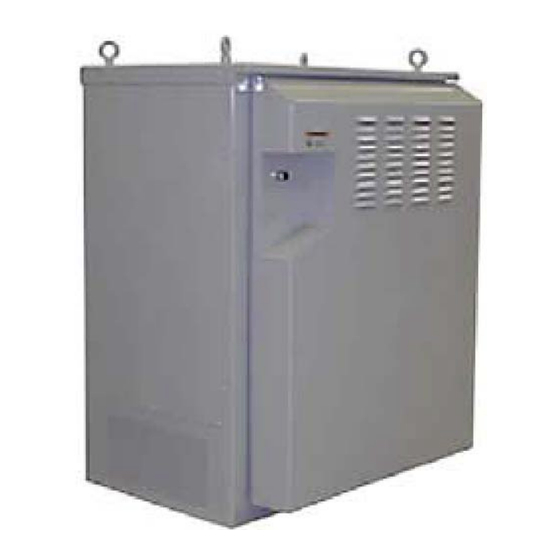
Page 13: Field Cabinet Description
• Durable baked-on polyester powder paint in an ultra-light gray color • High-gloss finish to minimize accumulation of dirt and soot • Aesthetically pleasing to enhance public acceptance • Security – Special hex key with padlock hasp used to open all doors (standard) ADC Telecommunications, Inc. -
Page 14: Weight
36 inches (914 mm) 23 inches (584 mm) nominal Width 30 inches (762 mm) 22 inches (559 mm) usable Depth 36” (914 mm) 30” (762 mm) 48” (1219 mm) 860131945-01.cdr Figure 1. PG-FlexPlus Field Cabinet Dimensions (Shown With Heat Exchanger) ADC Telecommunications, Inc. -
Page 15: Compartments
The electronics compartment also contains the Alarm Interface Panel (AIP) and 307 protector block, located to the left of the rack. The AIP provides an alarm interface and fusing for the field cabinet’s fans. The standard layouts of electronic equipment in each field cabinet are shown in Figure ADC Telecommunications, Inc. -
Page 16: Side Chamber
The PG-FlexPlus field cabinet was designed with new enhanced cooling features. The field cabinet uses a patent- pending enhanced cooling system, which includes: • 6F-fan units • Door ducts • Door-mounted heat exchanger No outside air is introduced into the electronics portion of the field cabinet for cooling purposes. ADC Telecommunications, Inc. -
Page 17: 6F-Fan Unit
Thermostat set points are listed in Table Table 3. Thermostat Temperature Set Points Thermostat Monitored Turn ON Turn OFF Type Temperature (±5°F) (±3°C) (±5°F) (±3°C) Battery 55°F (13°C) 37°F (3°C) Compartment High Equipment 131°F (55°C) 117°F (47°C) Compartment ADC Telecommunications, Inc. -
Page 18: Battery Heating And Cooling
This resulting reduction in battery temperature extends the life of batteries. ADC Telecommunications, Inc. -
Page 19: Site Planning
(2133 mm x 1892 mm) (2740 mm x 2590 mm) Figure 3 on page 9 shows the clearance areas required by the PG-FlexPlus field cabinet. See Field Cabinet Installation and the field cabinet foundation pad drawing, ED-1T339-01, for additional information. ADC Telecommunications, Inc. -
Page 20: Thermal Site Considerations
Whenever possible, a field cabinet should be located in vacant, unused, and out-of-sight portions of private, public, or commercial property with easy access and adequate parking. If a field cabinet must be located near a street or highway, it should be located away from curves and busy intersections. ADC Telecommunications, Inc. -
Page 21: Right-Of-Way
Site location efforts should be aimed at securing a permanent location that will prevent damage to the equipment and possible expensive relocation costs. ADC Telecommunications, Inc. -
Page 22: Field Cabinet Installation
A low-power heat source, such as an incandescent light bulb, located in the rack can also be used to provide humidity protection. A heat source should provide approximately 100 watts of heat. ADC Telecommunications, Inc. -
Page 23: Figure 4. Securing A Packed Field Cabinet For Shipping
July 19, 2004 SCP-PGCAB001-010-01H Block or secure base to prevent shifting 631600299-10.CDR Figure 4. Securing a Packed Field Cabinet for Shipping The factory-provided pallet is required to prevent cabinet damage Figure 5. Securing an Unpacked Field Cabinet for Shipping ADC Telecommunications, Inc. -
Page 24: Field Cabinet Placement
• 26 feet (8 m) of 2 AWG (35 mm ) bare solid copper ground wire • 2 ground rod clamps [for 2 AWG (35 mm ) wire]. Local practices and requirements may require additional materials. ADC Telecommunications, Inc. -
Page 25: Field Cabinet Grounding Requirements
(Install wire in optional ground wire duct, if provided.) 4. Connect ground wire to lug provided on the field cabinet ground bus. Use pliers to twist the self-threading lug onto the ground wire. ADC Telecommunications, Inc. -
Page 26: Figure 6. Grounding Requirements For Pg-Flexplus Field Cabinet (Shown With Field Cabinet Door Removed)
NEC code Section 250-83. of cabinet. Ground wire may not be spliced and should be routed as directly as possible. Figure 6. Grounding Requirements for PG-FlexPlus Field Cabinet (Shown With Field Cabinet Door Removed) ADC Telecommunications, Inc. -
Page 27: Figure 7. Grounding Requirements For Multi-Field Cabinet Installation
When distance “X” exceeds 6 feet (1.8 m), two ground rods are required with a minimum separation of 6 feet (1.8 m) between rods. Figure 7. Grounding Requirements for Multi-Field Cabinet Installation ADC Telecommunications, Inc. -
Page 28: Ac Service Installation
The maximum input current of the PG-FlexPlus field cabinet is listed in Table Table 5. Maximum Current Consumption of Standard Field Cabinet Configurations Maximum Current Consumption (Amps) Field Cabinet Configuration 120 V AC (L1) 120/240 V AC (L1/L2) 208Y/120 V AC (L1/L2) 14/14 14/14 1 String (120 Amp-hrs) ADC Telecommunications, Inc. -
Page 29: Bulk Power System
–48 V DC Bus from utility Panel Rectifiers and equipment Fuses –48 V DC –48 V DC –48 V DC Battery Battery Circuit Strings Breakers* 945-08.CDR * Part of Valere Power System Figure 8. Bulk Power System Block Diagram ADC Telecommunications, Inc. -
Page 30: Valere Power System
The rectifiers generate –48 V DC from 120/208/240 V AC input. The –48 V DC outputs of all rectifiers are tied together on a backplane bus. A minimum number of rectifiers are required to power the equipment and charge the batteries. ADC Telecommunications, Inc. -
Page 31: Batteries
–48 V DC power to the cabinet’s fans and to the control circuitry on the AIP. In some cases, these supplementary fuses may be used to power additional cabinet equipment. ADC Telecommunications, Inc. -
Page 32: Metallic Cable Termination And Wiring
If the utility connections have not been installed and electric tools or lighting are required, arrange for a temporary power source to be available at the field cabinet site. Electric tools and temporary lights may be plugged into the PG-FlexPlus field cabinet's ground fault circuit interrupt (GFCI) protected convenience outlets. ADC Telecommunications, Inc. -
Page 33: Field Cabinet And Hardware Preparation
* The (x-y) refers to the first and last pairs used in the particular sheath. 8. When splicing, ensure that the field cabinet pairs to be spliced are routed over previously spliced cables and under any unspliced cables (to prevent tangling). ADC Telecommunications, Inc. -
Page 34: Digital Cable Pair Splicing And Termination
Mini Fiber Panel, if used. 5. Using wire ties, secure the OSP and field cabinet cables together as necessary. ADC Telecommunications, Inc. -
Page 35: Table 8. Network T1/Hdsl Cable Assignments
Transmit/Loop 2 HyperEdge 2 position #3 Slate Transmit/Loop 2 HyperEdge 2 position #4 Black Blue Transmit/Loop 2 HyperEdge 2 position #5 Black Orange Transmit/Loop 2 HyperEdge 2 position #6 38-50 Not Used * Wired for future use ADC Telecommunications, Inc. -
Page 36: Pg-Flexplus Hdsl (Tip/Ring) Pairs And Test Pair Splicing
6. The test by-pass pair is spliced to the D (100) connector. Follow general splicing procedure as noted above (refer to Table 11 on page 33). Splice Completion After completing all splicing operations, replace the splice chamber cover. ADC Telecommunications, Inc. -
Page 37: Table 9. Pg-Flexplus Hdsl Cable Assignments
Loop 2 Power 6 Black Orange Loop 2 HDSL 6 Black Green Loop 2 Power 7 Black Brown Loop 2 HDSL 7 Black Slate Loop 2 Power 8 Yellow Blue Loop 2 HDSL 8 92-99 Not Used ADC Telecommunications, Inc. -
Page 38: Intrashelf Connection
Protectors ordered with the PG-FlexPlus field cabinet are packed in the battery compartment. Do not use protector units equipped with heat coils. Heat-coil type protectors may fail CAUTION prematurely due to normal operating temperatures in outdoor field cabinets. ADC Telecommunications, Inc. -
Page 39: Alarm Interface Panel
DC Test Pair wiring for specific model configurations. Under no circumstances should any wiring additions, deletions, or changes be made to the alarm WARNING interface panel. Improper or unauthorized changes could damage the power system and/or the PG-Flex Plus PMU-712. ADC Telecommunications, Inc. -
Page 40: Battery Installation
Do not move the field cabinet with batteries in place. Install the batteries only after the field CAUTION cabinet is installed in its final position. The field cabinet structure can be damaged if the field cabinet is lifted with batteries installed. ADC Telecommunications, Inc. -
Page 41: Ir-30, Ir-40, And Tel-12-45 Slc Battery Installation
7. Plug each battery into the battery cable as shown in Figure 11 on page (–) Battery connector Thermal probe (Install thermal probe ring lug beneath the factory-installed ring lug.) 631600293-39.CDR Probe cable (to Valere) Figure 10. Securing the Thermal Probes to Tyco IR-30 or IR-40 Batteries ADC Telecommunications, Inc. -
Page 42: Figure 11. Tyco Ir-30 Or Ir-40 Battery Installation Layout In Pg-Flexplus Field Cabinet
(4 per battery string) Secure thermal probes rear of cabinet To power supply 860131945-10.cdr Battery string number 1 cable Battery string number 2 cable Figure 11. Tyco IR-30 or IR-40 Battery Installation Layout in PG-FlexPlus Field Cabinet ADC Telecommunications, Inc. -
Page 43: Tyco 12Ir125 Or C&D Fa12-125 Battery Installation
9. Locate the battery thermal probe and four battery extension cables in the battery compartment. These cables are packaged in plastic bags and are secured in the battery tray in the bottom of the cabinet. 10.Dress the temperature probe to the side and plug it the Valere Power Shelf. ADC Telecommunications, Inc. -
Page 44: Figure 12. 12Ir125 Battery Installation Layout (Pg-Flexplus Field Cabinet Shown)
(provided with batteries) Figure 12. 12IR125 Battery Installation Layout (PG-FlexPlus Field Cabinet Shown) 12IR125 batteries Part of Group 63 battery string cable 631600293-42.CDR Interbattery bus bar Figure 13. Tyco 12IR125 or C&D FA12-125 Battery Installation and Interconnection ADC Telecommunications, Inc. -
Page 45: Replacement And Repair Parts
“*”. Additional parts are listed in Table 12 on page 34. Contact ADC customer support for these parts or other parts not listed. Table 11. Replacement and Repair Parts Item... -
Page 46: Table 12. Miscellaneous Supplemental Items
L-Connector Presser Tool 402 490 064 Used for joining 710 bridging and splicing modules to each other W4DF Test Cord 105 329 395 Looping test cord. May be used for fault locating T1 extensions via the 307 block protectors ADC Telecommunications, Inc. -
Page 47: Cabinet Power System Turn-Up
4. Locate the Battery Circuit Breakers and place all breakers in the OFF position. 5. Connect your ESD wrist strap to a cabinet grounding point and make sure that it is connected at all times when handling any of the Valere molules or other plug-ins. ADC Telecommunications, Inc. -
Page 48: Installing The System Controller
2. Return all Battery Circuit Breakers (with battery strings attached to them) to the On position. If the batteries’ storage temperature exceeds 32°C (90°F), their open circuit time should not WARNING exceed 4 months. For maximum safety, do not handle the batteries during their initial 24 hour charging period. WARNING ADC Telecommunications, Inc. -
Page 49: Test Access And Alarms
(not provided with cabinet) may be used for fault locating (Figure 14). Equipment side-TIP Equipment side-RING OSP side-TIP OSP side-RING Ground Ground 463A 463A OSP side-RING OSP side-TIP Equipment side-RING Equipment side-TIP 3 ft. (0.9 m) 631600293-73.CDR Figure 14. W4DF Looping Test Cord ADC Telecommunications, Inc. -
Page 50: Figure 15. 6W3E Test Cord
Equipment side-TIP OSP side-TIP OSP side-RING 463A PLUG Equipment side-RING Ground 526A PLUG RING 5 feet (1.5 m) 631600293-71.CDR Figure 15. 6W3E Test Cord DC test (to AIP) C(1) DC test Figure 16. Wiring of Miscellaneous Pairs ADC Telecommunications, Inc. -
Page 51: Alarms
Under no circumstances should any wiring additions, deletions, or changes be made to the alarm WARNING interface panel. Improper or unauthorized changes could damage the power system and/or the PG-Flex Plus PMU-712. ADC Telecommunications, Inc. -
Page 52: Figure 17. Alarm Interface Panel
SCP-PGCAB001-010-01H July 19, 2004 BATT CB ALARM FAN ALARM FUSE ALARM NORMAL ALARM INTERCONNECT PANEL ALARM INTERCONNECTS P220 P221 P222 P223-1 P223-2 P224 631600293-74.CDR Order wire terminals Figure 17. Alarm Interface Panel ADC Telecommunications, Inc. -
Page 53: Figure 18. Front View Cabinet Alarms To Alarm Inputs
July 19, 2004 SCP-PGCAB001-010-01H Figure 18. Front View Cabinet Alarms to Alarm Inputs ADC Telecommunications, Inc. -
Page 54: Troubleshooting
• Major Fuse Alarm: blown fuse, also included Power Major above (See Schematic and/or field cabinet labeling for fuse assignments) • Battery on Discharge • AC Failure: loss of AC input voltage to at least one rectifier ADC Telecommunications, Inc. -
Page 55: Field Cabinet Environmental Alarms
Closure to –48 V Isolated Closure Power Major MJP, MJPR Red Fuse Alarm LED on AIP Closure to –48 V MNP, MNPR Isolated Closure Power Minor Yellow FUSE ALARM LED on AIP and Blown Fuse (F21-F24) Closure to –48 V ADC Telecommunications, Inc. -
Page 56: Intrusion Alarm
The door switch can be pulled out to retire the intrusion alarm when servicing the cabinet. The switch will reset when the door is closed. Standard Door Switch Pull to retire remoted intrusion alarm (resets when door is closed) 631600293-76.CDR Figure 19. Door Switch ADC Telecommunications, Inc. -
Page 57: Field Equipment Installation And Cabinet Maintenance
(four total). 6. Mate all cabinet wiring to subrack connectors as shown on the Schematic Diagram. 7. Once the equipment is installed and all connections made, neatly dress and secure all cables. ADC Telecommunications, Inc. -
Page 58: Maintenance
1. For field cabinets that are mounted on a pole-mount or H-frame/wall-mount bracket, inspect the bracket for rust and/or damage. Pay particular attention to the four inserts in the rear side of the field cabinet. 2. If required, touch-up and/or repair as necessary. ADC Telecommunications, Inc. -
Page 59: Fan Replacement Procedures
10.Insert the AIP fuse(s) feeding power to the bay fans. 11.Check for airflow at the front of the fan to ensure that the fans are functioning. 12.Check to ensure that no fan or fuse alarms are active. ADC Telecommunications, Inc. -
Page 60: Batteries
2. Follow the leads from the thermostat to the connector and disconnect it. 3. Using a VOM set to measure resistance, insert the VOM’s probes into the connector attached to the heater pad and measure its resistance. 4. Verify that the reading is per Table 16 on page ADC Telecommunications, Inc. -
Page 61: Battery Heater Pad Replacement Procedure
11.Install the thermostat of the new pad as the old thermostat was installed. 12.Connect the new pad to the cabinet wiring. 13.Turn on the battery heater circuit breaker at the AC panel. 14.Reinstall the batteries following the instructions provided in this section. ADC Telecommunications, Inc. - Page 62 SCP-PGCAB001-010-01H July 19, 2004 ADC Telecommunications, Inc.
-
Page 63: Glossary
Digital Pairs – DS0 circuits from a channel bank, also called Voice Frequency (VF) Pairs, although not always analog. See DS1 or T1. DS0 – Voice channel, specifically 64 kbit/s equivalent digital bandwidth. Bi-directional, typically carried on one twisted pair. ADC Telecommunications, Inc. - Page 64 Miscellaneous Pairs – Usually refers to dedicated twisted pairs from CO to RT enclosure which are not in the transmission path and are used for test and troubleshooting. Typically include DC Test, Order Wire, and Fault Locate Pairs. ADC Telecommunications, Inc.
- Page 65 SDH – Synchronous Digital Hierarchy, the current European standard signal rates and formats for digital transmission, adopted and renamed by Telcordia as SONET. SD – Schematic Drawing SM – Singlemode, fiber type with a core diameter in which only a single mode, the fundamental mode, is capable of propagation ADC Telecommunications, Inc.
- Page 66 In safety (for example, UL) terms: a building or space in a building that is accessible by untrained personnel. VF – Voice Frequency, refers to analog DS0 services, often used to mean any DS0 service (see Derived Pairs). ADC Telecommunications, Inc.
-
Page 67: Product Support
ADC’s Return Material Authoriza- tion (RMA) Department. 2. Call or write ADC’s RMA Department to ask for an RMA number and any additional instructions. Use the tele- phone number, fax number or email address listed below: •... -
Page 68: Fcc Classa Compliance
SCP-PGCAB001-010-01H July 19, 2004 5. Write ADC’s address and the RMA Number you received from the RMA Department clearly on the outside of the carton. All shipments are to be returned prepaid. ADC will not accept any collect shipments. FCC C... - Page 70 World Headquarters: ADC Telecommunications, Inc. PO Box 1101 Minneapolis, Minnesota USA 55440-1101 For Technical Assistance: 800.366.3891 ´,s^¶06¨ 1283620...
Need help?
Do you have a question about the PG-FlexPlus PG-CAB001 and is the answer not in the manual?
Questions and answers