Table of Contents
Advertisement
Quick Links
Advertisement
Table of Contents

Subscribe to Our Youtube Channel
Related Manuals for Evco Vcolor 679


Summary of Contents for Evco Vcolor 679
- Page 1 EVCO S.p.A. Vcolor 679/689 | Installer manual ver. 1.0 | Code 144VC679E104 Vcolor 679/689 Controllers for retarding-proofing or proofing cabinets and rooms with customised graphic skin ENGLISH INSTALLER MANUAL ver. 1.0 CODE 144VC679E104 page...
- Page 2 EVCO S.p.A. Vcolor 679/689 | Installer manual ver. 1.0 | Code 144VC679E104 Important Read this document carefully before installation and before using the device and take all the prescribed precautions. Keep this document with the device for future consultation. Only use the device in the ways described in this document. Do not use the device as a safety device.
-
Page 3: Table Of Contents
EVCO S.p.A. Vcolor 679/689 | Installer manual ver. 1.0 | Code 144VC679E104 Contents INTRODUCTION ............ 4 10.1 ON-OFF / variable speed compressor management Introduction ............4 (for retarding-proofing only) ......... 39 Models available and main features ......5 10.2 Pump-down... -
Page 4: Introduction
The evaporator fan can also be modulated using an EVCO inverter. In the 689 models, the modulating output can also be set to control variable speed compressors. -
Page 5: Models Available And Main Features
EVCO S.p.A. Vcolor 679/689 | Installer manual ver. 1.0 | Code 144VC679E104 Models available and main features The table below shows the main features of the models available. KITS OPTIONS I/O expansion Speed Inverter module regulator Vcolor 689 M & L MAIN FEATURES Vcolor 679 M &... - Page 6 EVCO S.p.A. Vcolor 679/689 | Installer manual ver. 1.0 | Code 144VC679E104 KITS OPTIONS I/O expansion Speed Inverter module regulator Vcolor 689 M & L MAIN FEATURES Vcolor 679 M & L with 0-10 V EVDFAN1 Compact, with PWM output...
- Page 7 EVCO S.p.A. Vcolor 679/689 | Installer manual ver. 1.0 | Code 144VC679E104 KITS OPTIONS I/O expansion Speed Inverter module regulator Vcolor 689 M & L MAIN FEATURES Vcolor 679 M & L with 0-10 V EVDFAN1 Compact, with PWM output...
-
Page 8: Measurements And Installation
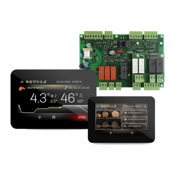
EVCO S.p.A. Vcolor 679/689 | Installer manual ver. 1.0 | Code 144VC679E104 MEASUREMENTS AND INSTALLATION Format features The control module is available in a split version with an open frame board. User interfaces are available in 5- or 7-inch versions for horizontal operation and have capacitive colour TFT touch-screen graphic displays. -
Page 9: User Interface Installation
EVCO S.p.A. Vcolor 679/689 | Installer manual ver. 1.0 | Code 144VC679E104 Vcolor 679/689 L interface User interface installation Depending on the model, installation can be: flush, from behind the panel with threaded studs (not provided) welded to hold it in place;... -
Page 10: Evc20P52N9Xxx10 - Evc20P52N9Xxx12 Expansion Module Measurements And Installation
EVCO S.p.A. Vcolor 679/689 | Installer manual ver. 1.0 | Code 144VC679E104 EVC20P52N9XXX10 – EVC20P52N9XXX12 expansion module measurements and installation The diagram below shows the measurements of the 4 relay expansion. Installation is on a flat surface with spacers. Installation precautions Ensure that the working conditions for the device (operating temperature, humidity, etc.) are within the set limits. -
Page 11: Electrical Connection
EVCO S.p.A. Vcolor 679/689 | Installer manual ver. 1.0 | Code 144VC679E104 ELECTRICAL CONNECTION Vcolor 679/689 M electrical connection The diagram below shows the Vcolor 679/689 M electrical connection. *The USB communications port makes it possible to upload and download the device settings and personalise the graphics, recipes and languages using an ordinary USB flash drive (see section 11 “USB PORT MANAGEMENT”). -
Page 12: Vcolor 679/689 L Electrical Connection
EVCO S.p.A. Vcolor 679/689 | Installer manual ver. 1.0 | Code 144VC679E104 Vcolor 679/689 L electrical connection The diagram below shows the Vcolor 679/689 L electrical connection. *The USB communications port makes it possible to upload and download the device settings and personalise the graphics, recipes and languages using an ordinary USB flash drive (see section 11 “USB PORT MANAGEMENT”). -
Page 13: Precautions For Electrical Connection
To reduce reflections on the signal transmitted along the cables connecting the user interface to the control module, it is necessary to fit a termination resistor. For repairs and for further information on the device, contact the EVCO sales network. page... -
Page 14: Retarding-Proofing Or Proofing Operation
Initial information Vcolor 679/689 is a controller which, by simply setting a parameter, can be configured to manage retarding-proofing cabinets and rooms (E12 = 1) or proofing cabinets and rooms (E12 = 0). All the cooling regulations are for retarding-proofing only; care must therefore be taken when configuring the controller for proofing (E12 = 0), that no parameters are set for cooling (see section 14. - Page 15 EVCO S.p.A. Vcolor 679/689 | Installer manual ver. 1.0 | Code 144VC679E104 Retarding-proofing Proofing Home screen (E12=0) Home screen (E12=1) To switch the device on, press the central key on the stand-by screen; to switch the device off, press the key on the lower part of the Home screen.
-
Page 16: Navigation
EVCO S.p.A. Vcolor 679/689 | Installer manual ver. 1.0 | Code 144VC679E104 NAVIGATION Initial information Navigating the menus is intuitive, based on touch technology. To enter into a procedure, touch the menu or the corresponding icon. To exit a procedure and, in general, to return to the previous level, use the keys. -
Page 17: Cycle Running Screen
EVCO S.p.A. Vcolor 679/689 | Installer manual ver. 1.0 | Code 144VC679E104 Cycle running screen Once a cycle has been started up, the Run screen will appear for the type of cycle selected. Below are the screens for the retarding-proofing cycles (E12 = 1) - Page 18 EVCO S.p.A. Vcolor 679/689 | Installer manual ver. 1.0 | Code 144VC679E104 6.3.1 Regulator status icons While a cycle is being run, the status of the principal loads is displayed as icons on the upper part of the screen. Below are their meanings: On: compressor active;...
- Page 19 EVCO S.p.A. Vcolor 679/689 | Installer manual ver. 1.0 | Code 144VC679E104 6.3.2 Function keys When a cycle (both manual and automatic) is being configured or running, function keys will be displayed. Below are their meanings: switch light on/off select fan speed (if configured for several speeds)
-
Page 20: Screen Saver
EVCO S.p.A. Vcolor 679/689 | Installer manual ver. 1.0 | Code 144VC679E104 Screen saver After a period of inactivity set by parameter E0, whatever screen is active at the time will switch to the screen saver showing the values detected by the probes in use. This function can be disabled by setting parameter E0=0. - Page 21 EVCO S.p.A. Vcolor 679/689 | Installer manual ver. 1.0 | Code 144VC679E104 6.5.5 Counters (for retarding-proofing only) Reports of machine operation times are displayed (total hours of machine operation, total hours of compressor operation, average time the compressor was switched on, average time the compressor was switched off).
-
Page 22: Users
EVCO S.p.A. Vcolor 679/689 | Installer manual ver. 1.0 | Code 144VC679E104 6.5.8 Advanced This option gives access to the following sub-menu with the password -19: Users The controller can manage the three user levels listed below if parameter E9=1; the user levels can only be managed when logged in as ADMIN. -
Page 23: Overview Of The Functions
EVCO S.p.A. Vcolor 679/689 | Installer manual ver. 1.0 | Code 144VC679E104 OVERVIEW OF THE FUNCTIONS Automatic cycle The controller can automatically manage the entire dough retarding-proofing (E12 = 1) or proofing (E12 = 0) cycle. An automatic cycle consists of several phases with different temperatures, relative humidities, fan speeds and durations. There are 5 phases for configuring retarding-proofing (blocking, holding, re-awakening, proofing and baking delay) and 3 phases for configuring proofing (re-awakening, proofing and baking delay). - Page 24 EVCO S.p.A. Vcolor 679/689 | Installer manual ver. 1.0 | Code 144VC679E104 HOLDING phase (phase 2 retarding-proofing) Temperature regulation is active and has a neutral zone adjustment, the temperature setpoint, humidity setpoint (if control of this is required) and fan speed are set by the end user.
- Page 25 EVCO S.p.A. Vcolor 679/689 | Installer manual ver. 1.0 | Code 144VC679E104 PROOFING phase (phase 4 retarding-proofing; phase 2 proofing) Retarding-proofing: Proofing: Temperature regulation is active and has a neutral zone adjustment, the working setpoint is set by the end user. Moving from the re- awakening setpoint (previous phase) to the proofing setpoint can be gradual, with the incremental percentages set while the parameters are being set (parameters rL0 - rL10).
- Page 26 EVCO S.p.A. Vcolor 679/689 | Installer manual ver. 1.0 | Code 144VC679E104 BAKING DELAY phase (optional: phase 5 retarding-proofing; phase 3 proofing) Retarding-proofing: Proofing: Depending on the needs of the user, the baking delay phase can be disabled (the cycle is automatically interrupted at the end of the proofing phase) or enabled with a predefined time (the cycle is automatically interrupted at the end of the counter) or an infinite duration by the end user (the cycle is automatically interrupted by holding down the STOP key).
-
Page 27: Manual Cycles
EVCO S.p.A. Vcolor 679/689 | Installer manual ver. 1.0 | Code 144VC679E104 Summary of cycle phases and changing the phases By pressing the area in the table while the cycle is running, a summary of the cycle with information about each phase is displayed. -
Page 28: Main Functions
EVCO S.p.A. Vcolor 679/689 | Installer manual ver. 1.0 | Code 144VC679E104 MAIN FUNCTIONS Automatic cycle 8.1.1 Selecting, changing and starting up an automatic cycle Every automatic cycle is selected, changed and started up from the default recipe or a pre-existing recipe. Press the automatic cycle area and view the recipes: Upon selecting the desired recipe, a table with a summary of the settings for every phase is displayed. - Page 29 EVCO S.p.A. Vcolor 679/689 | Installer manual ver. 1.0 | Code 144VC679E104 If, instead, the description of the recipe is pressed, a screen with a keyboard will open. Pressing on the table will give access to the single screens where changes can be made to each phase (which make up a RETARDING-...
- Page 30 EVCO S.p.A. Vcolor 679/689 | Installer manual ver. 1.0 | Code 144VC679E104 Changing fan speed depends on parameter E7. If E7=0, the mode is single speed and cannot be changed. Otherwise, the following changes are possible: if E7=1 or 4, the speed is single or double and can be...
- Page 31 EVCO S.p.A. Vcolor 679/689 | Installer manual ver. 1.0 | Code 144VC679E104 8.1.3 Automatic cycle options The following actions can be taken from the screen with the table of the cycle/recipe: start the cycle/recipe as configured in the table overwrite a cycle/recipe which has previously been selected and changed...
-
Page 32: Heating Cycle
EVCO S.p.A. Vcolor 679/689 | Installer manual ver. 1.0 | Code 144VC679E104 Heating cycle When this cycle is selected for the first time, the following screen will be displayed, suggesting the preloaded values; if any changes are made to these values, they will be suggested the next time the cycle is selected. -
Page 33: Cooling Cycle (For Retarding-Proofing Only)
EVCO S.p.A. Vcolor 679/689 | Installer manual ver. 1.0 | Code 144VC679E104 Cooling cycle (for retarding-proofing only) When this cycle is selected for the first time, the following screen will be displayed, suggesting the preloaded values; if any changes are made to these values, they will be suggested the next time the cycle is selected. -
Page 34: Pre- Cooling Cycle (For Retarding-Proofing Only)
EVCO S.p.A. Vcolor 679/689 | Installer manual ver. 1.0 | Code 144VC679E104 Pre- cooling cycle (for retarding-proofing only) A pre-cooling cycle can be activated in the chamber while waiting for the retarding-proofing cycle to be selected. Pressing the pre-cooling key opens up a screen where the cabinet temperature setpoint and the speed of the evaporator fan can be set. -
Page 35: Recipe Book
EVCO S.p.A. Vcolor 679/689 | Installer manual ver. 1.0 | Code 144VC679E104 Recipe book There are two sections called RECIPE BOOK and FAVOURITES. In the RECIPE BOOK section, users can save up to 99 cycles/recipes; only cycles/recipes which have previously been labelled with the icon in the RECIPE BOOK can be stored in the FAVOURITES section. -
Page 36: Regulations
EVCO S.p.A. Vcolor 679/689 | Installer manual ver. 1.0 | Code 144VC679E104 REGULATIONS Pre-cooling (for retarding-proofing only) The purpose of the pre-cooling cycle is to bring the cabinet to a certain temperature (set by parameter rC6) before selecting and running a retarding-proofing cycle. -
Page 37: Humidity Regulation
EVCO S.p.A. Vcolor 679/689 | Installer manual ver. 1.0 | Code 144VC679E104 Humidity regulation In all phases where this is required, the humidity is regulated with an EVHTP520 probe or a humidity transducer 4÷20 mA (Ru0=0 and P12≠0). It is enabled in the neutral zone where two values are set, one above and one below the humidity setpoint, thus creating a zone inside which the loads for humidification and dehumidification are not activated. - Page 38 EVCO S.p.A. Vcolor 679/689 | Installer manual ver. 1.0 | Code 144VC679E104 9.3.2 Dehumidification management Dehumidification is managed by an extractor fan/dehumidifier (u3=0) when configured for proofing, whereas in the configuration for retarding-proofing, it can also be controlled by activating the refrigeration plant (u3=1).
-
Page 39: Load Management
10.3 Evaporator fan management N.B.: the evaporator fan can be managed by the PWM output (Vcolor 679) or the 0-10 VDC output (Vcolor 689) depending on the model. -
Page 40: Defrost Management (For Retarding-Proofing Only)
The controller can automatically detect the presence of an EVCO inverter. By setting parameter E10=2 (or E10=3 if there is also a relay expansion) and E7=2, the system starts up again on the HOME page. -
Page 41: Steam Generator Output Management
EVCO S.p.A. Vcolor 679/689 | Installer manual ver. 1.0 | Code 144VC679E104 10.6 Steam generator output management Management of the steam generator load depends on the setting of parameters E3, E4 and E5. More precisely: E4=0 Output always active when a cycle is running. -
Page 42: Dehumidification Management
EVCO S.p.A. Vcolor 679/689 | Installer manual ver. 1.0 | Code 144VC679E104 10.8 Dehumidification management Dehumidification management is only active when humidity is managed by a humidity probe/transducer (rU0 = 0). Dehumidification can be managed in the first mode described below when configuring proofing and in both modes when configuring retarding-proofing: using an extraction fan with “uxc=15”... -
Page 43: Testing Cycle
EVCO S.p.A. Vcolor 679/689 | Installer manual ver. 1.0 | Code 144VC679E104 10.14 Testing cycle The password to enter this mode is -19. A completely automatic testing cycle can be performed in this mode. If proofing is configured, the testing cycle only applies to the heating phase (see point 1 below). -
Page 44: Connectivity
EVCO S.p.A. Vcolor 679/689 | Installer manual ver. 1.0 | Code 144VC679E104 11 CONNECTIVITY 11.1 Initial information Users can interact remotely with their equipment and start up/stop working cycles using the EPoCA cloud platform with Wi-Fi or Ethernet connectivity (which also enable alternative or parallel control through MODBUS TCP). For more details, compare the connectivity options in the “Models available and technical features”... -
Page 45: Epoca Cloud Platform
HVAC units in response to market demand. To connect to the cloud system and remotely control machinery from a PC, tablet or smartphone, all users need is an EVCO controller with native EPoCA®... -
Page 46: Usb Port Management
EVCO S.p.A. Vcolor 679/689 | Installer manual ver. 1.0 | Code 144VC679E104 12 USB PORT MANAGEMENT 12.1 Available functions The USB port provides the following functions: download to a USB flash drive the data relating to the cycles performed (HACCP history) -
Page 47: Alarms
EVCO S.p.A. Vcolor 679/689 | Installer manual ver. 1.0 | Code 144VC679I104 13 ALARMS When an alarm occurs, a red bar will appear at the top of the screen of the cycle in progress, and the buzzer, if enabled, will begin to sound; if several alarms are in progress at the same time, they will alternate on the bar every 3 seconds. -
Page 48: List Of Alarms
EVCO S.p.A. Vcolor 679/689 | Installer manual ver. 1.0 | Code 144VC679I104 13.2 List of alarms The table below lists all the possible alarms. The alarms highlighted in grey do not occur when proofing is configured (E12 = 0). Alarm... - Page 49 EVCO S.p.A. Vcolor 679/689 | Installer manual ver. 1.0 | Code 144VC679I104 the evaporator fan, humidifier, steriliser/oxygenator and heaters will be switched off To correct: POWER OUTAGE check the device-power supply connection To correct: check the condenser temperature CONDENSER PRE-ALARM...
- Page 50 EVCO S.p.A. Vcolor 679/689 | Installer manual ver. 1.0 | Code 144VC679I104 Main results: none; this is only a visual alarm and has no effect on regulation To correct: - re-set the date and time Main results: the device is unable to start up automatic cycles...
-
Page 51: Parameters
EVCO S.p.A. Vcolor 679/689 | Installer manual ver. 1.0 | Code 144VC679I104 14 PARAMETERS The table below describes the configuration parameters of the device when it is set to manage retarding-proofing (E12 = 1). To control proofing (E12 = 0), always refer to the table below, except for the parameters highlighted in grey which have no meaning in this configuration; with E12=0, remember to assign the correct values (namely those in grey in the “Default”... - Page 52 EVCO S.p.A. Vcolor 679/689 | Installer manual ver. 1.0 | Code 144VC679I104 15.0 °C parameter rC3, rC4, rC5 differential minimum setpoint that can be set for the blocking, holding, -99.0 °C -20.0 manual cooling and pre-cooling phases maximum setpoint that can be set for the blocking, holding, 99.0...
- Page 53 EVCO S.p.A. Vcolor 679/689 | Installer manual ver. 1.0 | Code 144VC679I104 percentage increase for the 9th re-awakening step (out of a total of 100%) percentage increase for the 10th re-awakening step (out of a rr10 total of 100%) - - - -...
- Page 54 EVCO S.p.A. Vcolor 679/689 | Installer manual ver. 1.0 | Code 144VC679I104 humidification proportional band value (only for E3=0 and rU10 % r.H. E6=0) cycle time for humidification proportional regulation (only for rU11 E3=0 and E6=0) time base for humidification proportional regulation cycle...
- Page 55 EVCO S.p.A. Vcolor 679/689 | Installer manual ver. 1.0 | Code 144VC679I104 Par. Unit Default Defrost automatic defrost interval = defrost at intervals is never activated type of defrost = electrical (during defrosting the compressor is switched off, the defrost output is activated and the...
- Page 56 EVCO S.p.A. Vcolor 679/689 | Installer manual ver. 1.0 | Code 144VC679I104 buzzer reactivation time if alarm(s) still active = not enabled alarm output activation - - - - = with alarm active = with alarm not active Par. Unit...
- Page 57 EVCO S.p.A. Vcolor 679/689 | Installer manual ver. 1.0 | Code 144VC679I104 activated for the blocking, holding and manual cooling phases evaporator fan mode during defrost - - - - = off = on speed 1 evaporator fan, if E7=2 or 3...
- Page 58 EVCO S.p.A. Vcolor 679/689 | Installer manual ver. 1.0 | Code 144VC679I104 the light key has priority over the door switch; if the light has been switched on with the key, the door opening or closing will have no effect on light status...
- Page 59 EVCO S.p.A. Vcolor 679/689 | Installer manual ver. 1.0 | Code 144VC679I104 Par. Unit Default Configurable digital outputs enable light key = no - - - - = yes N.B.: if u1=0 and a relay is configured as the light, it will be controlled by the door switch.
- Page 60 EVCO S.p.A. Vcolor 679/689 | Installer manual ver. 1.0 | Code 144VC679I104 load associated with output K10 (see u1c), only with u10c - - - - expansion load associated with output K11 (see u1c), only with u11c - - - -...
- Page 61 EVCO S.p.A. Vcolor 679/689 | Installer manual ver. 1.0 | Code 144VC679I104 setpoint duration of “cycle completed” display = not enabled type of steam generator - - - - = humidifier with steamer/instant generator steam generator relay management = always ON = ON only if the phase requires humidity and if the chamber probe<setpoint (of the phase in progress)
- Page 62 Check that the settings for the percentages and number of steps are consistent. The value set for parameter E7 only applies to Vcolor 679 models with PWM output; make sure the parameter is set correctly in Vcolor 689 models with 0-10V output.
-
Page 63: Accessories
EVCO S.p.A. Vcolor 679/689 | Installer manual ver. 1.0 | Code 144VC679I104 15 ACCESSORIES 15.1 4 relay expansion EVC20P52N9XXX10: 4 electro-mechanical relays EVC20P52N9XXX12: 4 HC sealed relays 15.2 Phase cutting speed regulator EVDFAN1 Makes it possible to regulate single-phase fan speed with a PWM command signal. The maximum operating current is 5 A. -
Page 64: Safety Transformer
EVCO S.p.A. Vcolor 679/689 | Installer manual ver. 1.0 | Code 144VC679I104 15.4 Safety transformer ECTSFD004 The transformer can power the user interface. 15.5 Non-optoisolated RS-485/USB serial interface EVIF20SUXI The interface enables the device to be connected to the Parameters Manager set-up software system. -
Page 65: Evlinking Wi-Fi Rs-485 Module
EVCO S.p.A. Vcolor 679/689 | Installer manual ver. 1.0 | Code 144VC679I104 15.9 EVlinking Wi-Fi RS-485 module EVIF25SWX Through the RS-485 communications port, the module provides the controller with Wi-Fi connectivity which enables remote management and monitoring from the Internet using the EPoCA® cloud system. -
Page 66: Technical Specifications
EVCO S.p.A. Vcolor 679/689 | Installer manual ver. 1.0 | Code 144VC679I104 16 TECHNICAL SPECIFICATIONS 16.1 Technical data Purpose of the control device: function controller Construction of the control device: built-in electronic device user interface control module Housing: black, self-extinguishing plastic open frame board. - Page 67 Clock battery charging time: 24 h (the battery is charged by the power supply of the device) 5 inputs of which 3 for PTC/NTC (terminals 25 - 29), 1 for 4-20mA (humidity probe, terminals 30 - 32), 1 for EVCO EVHTP520 humidity probe (terminals 23- PTC type analogue inputs Type of sensor: KTY 81-121 (990 @ 25°C, 77°F).
- Page 68 EVCO S.p.A. Vcolor 679/689 | Installer manual ver. 1.0 | Code 144VC679I104 Voltage-free Type of contact: 5 Vdc, 2 mA. Power supply: none Vcolor 679 models: 1 for PWM signal (for phase cutting speed regulator for single-phase EVDFAN1 fans) (terminals 33-34).
- Page 69 EVCO S.p.A. Vcolor 679/689 | Installer manual ver. 1.0 | Code 144VC679I104 Vcolor 679/689 Controller for retarding-proofing or proofing cabinets and rooms with customised graphic skin Installer manual ver. 1.0 PB - 29/22 Code 144VC679E104 This document and the solutions contained therein are the intellectual property of EVCO and thus protected by the Italian Intellectual Property Rights Code (CPI).
- Page 70 EVCO S.p.A. Vcolor 679/689 | Installer manual ver. 1.0 | Code 144VC679I104 EVCO S.p.A. Via Feltre 81, 32036 Sedico Belluno ITALY Tel. +39 0437/8422 | Fax +39 0437/83648 info@evco.it | www.evco.it page 70 of 70...
Need help?
Do you have a question about the Vcolor 679 and is the answer not in the manual?
Questions and answers