Table of Contents
Advertisement
Quick Links
EVCO S.p.A.
Vcolor 348 | Installer manual ver. 2.0 | Code 144VC348E204
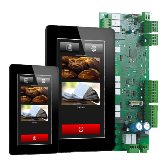
Vcolor 348 M & L
Controller for electric rotary ovens for bread
and pastry-making, with a 5 or 7-inch
colour TFT touch-screen graphic display, in
split version that can be built into the unit.
Installer Manual | ENGLISH
Code 144VC348E204
page 1 of 46
Advertisement
Table of Contents

Subscribe to Our Youtube Channel
Related Manuals for Evco Vcolor 348 Series


Summary of Contents for Evco Vcolor 348 Series
- Page 1 EVCO S.p.A. Vcolor 348 | Installer manual ver. 2.0 | Code 144VC348E204 Vcolor 348 M & L Controller for electric rotary ovens for bread and pastry-making, with a 5 or 7-inch colour TFT touch-screen graphic display, in split version that can be built into the unit.
- Page 2 EVCO S.p.A. Vcolor 348 | Installer manual ver. 2.0 | Code 144VC348E204 Important Read this document carefully before installation and before using the device and take all the prescribed precautions. Keep this document with the device for future consultation. Only use the device in the ways described in this document.
-
Page 3: Table Of Contents
EVCO S.p.A. Vcolor 348 | Installer manual ver. 2.0 | Code 144VC348E204 Index 1. INTRODUCTION ............4 13.1 Activating expansion ..........28 Introduction ............... 4 13.2 Electrical connection ..........28 Table listing the models available, their main features 13.3 Application diagram ........... 29 and purchasing codes .......... -
Page 4: Introduction
Vcolor 348 | Installer manual ver. 2.0 | Code 144VC348E204 INTRODUCTION Introduction The Vcolor 348 series is a range of stylish controllers for managing electric rotary ovens for bread and pastry-making. Available in split version, the user interface can be built into the unit mechanically for optimum aesthetic effect. - Page 5 EVCO S.p.A. Vcolor 348 | Installer manual ver. 2.0 | Code 144VC348E204 Table listing the models available, their main features and purchasing codes The table below lists the models available. Models available Vcolor 348 The table below shows the main features of the device.
- Page 6 EVCMC34DC2E Pt 100 2 wires Vcolor 348L (control module + 7-inch user interface kit) Purchasing codes EVCLC34DJ2E for J/K thermocouples EVCLC34DC2E Pt 100 2 wires Optional EVCLE305XXE boiler module EVCLE302XXE burner module For more models contact the EVCO sales network. page 6 of 46...
-
Page 7: Measurements And Installation
EVCO S.p.A. Vcolor 348 | Installer manual ver. 2.0 | Code 144VC348E204 MEASUREMENTS AND INSTALLATION Vcolor 348M user interface measurements The pictures below show the measurements of the 5-inch user interface; measurements are expressed in mm (inches). Vcolor 348L user interface measurements The pictures below show the measurements of the 7-inch user interface;... -
Page 8: User Interface Installation
EVCO S.p.A. Vcolor 348 | Installer manual ver. 2.0 | Code 144VC348E204 User interface installation The picture below shows the installation of the device user interface. The user interface is installed from behind using threaded studs, making the display flush with the front. -
Page 9: Installation Precautions
EVCO S.p.A. Vcolor 348 | Installer manual ver. 2.0 | Code 144VC348E204 Installation precautions Ensure that the working conditions for the device (operating temperatures, humidity, etc.) are within the set limits. See the section TECHNICAL SPECIFICATIONS. Do not install the device close to heat sources (heaters, hot air ducts, etc.), equipment with a strong magnetic field (large diffusers, etc.), in places subject to direct sunlight, rain, damp, excessive dust, mechanical vibrations or shocks. -
Page 10: Electrical Connection
EVCO S.p.A. Vcolor 348 | Installer manual ver. 2.0 | Code 144VC348E204 ELECTRICAL CONNECTION Vcolor 348M electrical connection The picture below shows the electrical connection of devices with a 5-inch user interface. For more information on how to manage ventilation see subsequent pictures. - Page 11 EVCO S.p.A. Vcolor 348 | Installer manual ver. 2.0 | Code 144VC348E204 page 11 of 46...
-
Page 12: Vcolor 348L Electrical Connection
EVCO S.p.A. Vcolor 348 | Installer manual ver. 2.0 | Code 144VC348E204 Vcolor 348L electrical connection The picture below shows the electrical connection of the device with a 7-inch user interface. For more information on how to manage ventilation see subsequent pictures. - Page 13 EVCO S.p.A. Vcolor 348 | Installer manual ver. 2.0 | Code 144VC348E204 page 13 of 46...
- Page 14 EVCO S.p.A. Vcolor 348 | Installer manual ver. 2.0 | Code 144VC348E204 Fan management in “on/off” mode at single speed (parameter F0 = 0). uscita 0-10 V (non utilizzata) 31 32 ventilatore abbattimento vapori rete elettrica Fan management in "on/off" mode at two-speed (parameter F0 = 2).
- Page 15 The RS-485 MODBUS port is the communications port with the following EVCO products: Parameters Manager set-up software system The USB port is the communications port for uploading and downloading the device settings using an ordinary USB flash drive.
-
Page 16: Precautions For Electrical Connection
To reduce reflections on the signal transmitted along the cables connecting the user interface to the control module it is necessary to fit a termination resistor For repairs and for further information on the device, contact the EVCO sales network. page 16 of 46... -
Page 17: Description
EVCO S.p.A. Vcolor 348 | Installer manual ver. 2.0 | Code 144VC348E204 DESCRIPTION User interface description The picture below shows the front view of the device user interface. The table below describes the front parts of the device user interface. - Page 18 EVCO S.p.A. Vcolor 348 | Installer manual ver. 2.0 | Code 144VC348E204 The picture below shows the back view of the device user interface. The table below describes the back parts of the device user interface. PART DESCRIPTION USB port...
-
Page 19: Control Module Description
EVCO S.p.A. Vcolor 348 | Installer manual ver. 2.0 | Code 144VC348E204 Control module description The diagram below shows the appearance of the device control module. The table below describes the parts of the device control module. PART DESCRIPTION K1 and K2 digital outputs... - Page 20 EVCO S.p.A. Vcolor 348 | Installer manual ver. 2.0 | Code 144VC348E204 digital outputs K10... K13 (not used) K9 digital output digital outputs K6... K8 digital outputs K3... K5 high voltage digital inputs For more information see subsequent sections. page 20 of 46...
-
Page 21: First-Time Use
EVCO S.p.A. Vcolor 348 | Installer manual ver. 2.0 | Code 144VC348E204 FIRST-TIME USE First-time use Proceed as follows. Install the device as shown in section 2 MEASUREMENTS AND INSTALLATION taking all the precautions mentioned in paragraph 0 Installation precautions. -
Page 22: Managing The Loads
EVCO S.p.A. Vcolor 348 | Installer manual ver. 2.0 | Code 144VC348E204 if parameter u1 is set at 1, the load will be a MANAGING THE LOADS motorised solenoid valve. Initial information The vent opens automatically and the end of each phase of the This paragraph describes the loads during normal usage. -
Page 23: Fume Reduction
EVCO S.p.A. Vcolor 348 | Installer manual ver. 2.0 | Code 144VC348E204 Fume reduction 6.10 Suction hood The fume reduction function is activated until the temperature The suction hood output is activated automatically when the detected by the fume probe reaches the temperature set by... -
Page 24: Cooking Cycle
EVCO S.p.A. Vcolor 348 | Installer manual ver. 2.0 | Code 144VC348E204 select COOKING CYCLE Repeat actions 5 and 6. Initial information Each cooking cycle is preceded by a pre-heating stage. The To set/scroll the cooking cycle phases, proceed as follows. -
Page 25: "My Recipes" Function
EVCO S.p.A. Vcolor 348 | Installer manual ver. 2.0 | Code 144VC348E204 "MY RECIPES" FUNCTION "WEEKLY PROGRAMMED Initial information SWITCH-ON" FUNCTION The "My Recipes" function makes it possible to save the 10.1 Initial information settings of a cooking cycle for a recipe. When the recipe is The “Weekly Programmed Switch-on”... -
Page 26: Activating The "Weekly Programmed Switch-On" Function
EVCO S.p.A. Vcolor 348 | Installer manual ver. 2.0 | Code 144VC348E204 10.3 Activating "Weekly OTHER FUNCTIONS programmed switch-on" 11.1 View alarm status The procedure operates as follows. function Ensure that the device is switched on and that no The procedure operates as follows. -
Page 27: Boiler Expansion
EVCO S.p.A. Vcolor 348 | Installer manual ver. 2.0 | Code 144VC348E204 BOILER EXPANSION 12.1 Activating expansion The following conditions must be met to enable to EVCLE305XXE boiler expansion. Enable the boiler by setting parameter T15 (T15 = 1) Set the steam generation mode with external or mixed humidification by setting parameter T0 (T0 = 1 or 2) Board on. -
Page 28: Burner Expansion
EVCO S.p.A. Vcolor 348 | Installer manual ver. 2.0 | Code 144VC348E204 BURNER EXPANSION 13.1 Activating expansion To enable burner expansion parameter b14 = 1 (gas oven) must be set. 13.2 Electrical connection Example for Vcolor 348L. page 28 of 46... -
Page 29: Application Diagram
EVCO S.p.A. Vcolor 348 | Installer manual ver. 2.0 | Code 144VC348E204 13.3 Application diagram The EVCLE302XXE burner module interacts with electronic ignition circuit boards for Honeywell series 4565 and similar atmospheric burners and with variable speed centrifugal fans with PWM control + feedback. -
Page 30: Operation
EVCO S.p.A. Vcolor 348 | Installer manual ver. 2.0 | Code 144VC348E204 13.4 Operation During the heating phase, the controller activates the chamber and boiler heating outputs also activating the relevant burner with a power in proportion to the distance from the temperature controlled by the working set-point by adjusting the rotation speed of the centrifugal fan. -
Page 31: Configuration
EVCO S.p.A. Vcolor 348 | Installer manual ver. 2.0 | Code 144VC348E204 CONFIGURATION 14.1 Setting the time, date and day of the week The procedure operates as follows. Ensure that the device is switched on and that no procedure is in progress. -
Page 32: List Of Configuration Parameters
EVCO S.p.A. Vcolor 348 | Installer manual ver. 2.0 | Code 144VC348E204 14.3 List of configuration parameters The table below describes the configuration parameters of the device. PARAM. MIN. MAX. U.M. DEF. ANALOGUE INPUTS Type of probe 0 = J thermocouple (only for J/K versions) - Page 33 EVCO S.p.A. Vcolor 348 | Installer manual ver. 2.0 | Code 144VC348E204 Minimum time between two consecutive output switch-ons for temperature adjustment (only valid if r13 = 1) Minimum on/off duration of the output for temperature adjustment (only valid if r13 = 1) Integral time (only valid if r13 = 1) PARAM.
- Page 34 EVCO S.p.A. Vcolor 348 | Installer manual ver. 2.0 | Code 144VC348E204 PARAM. MIN. MAX. U.M. DEF. STEAM INJECTION Steam generation mode 0 = direct - - - 1 = with an external humidifier 2 = combined (both directly and with an external humidifier)
- Page 35 EVCO S.p.A. Vcolor 348 | Installer manual ver. 2.0 | Code 144VC348E204 °C/°F (2) Unused Unused °C/°F (2) Unused Unused Alarm activation delay for water at minimum level Alarm activation delay for water at maximum level Humidification value display - - -...
- Page 36 EVCO S.p.A. Vcolor 348 | Installer manual ver. 2.0 | Code 144VC348E204 Duration of the venting output stoppage from the end of the short ds (s/10) pulse for opening the vent and from the end of the long pulse for closing it (only if u1 = 1).
- Page 37 EVCO S.p.A. Vcolor 348 | Installer manual ver. 2.0 | Code 144VC348E204 Unused Unused °C/°F (2) Unused Unused Unused Unused °C/°F (2) Unused Unused °C/°F (2) Unused Unused Unused Unused °C/°F (2) Unused °C/°F (2) Unused Unused PARAM. MIN. MAX.
-
Page 38: Using The Usb Port
EVCO S.p.A. Vcolor 348 | Installer manual ver. 2.0 | Code 144VC348E204 The unit of measurement depends on parameter P1 If the power failure duration is lower than the time set by parameter r12, when power is restored the cycle will be restarted from the beginning of cycle in which the power failed. -
Page 39: Alarms
EVCO S.p.A. Vcolor 348 | Installer manual ver. 2.0 | Code 144VC348E204 ALARMS 16.1 Alarms If an alarm happens the buzzer sounds and the display shows the icon and an alarm code. Touch the display near the centre to silence the buzzer and restore the normal view. - Page 40 EVCO S.p.A. Vcolor 348 | Installer manual ver. 2.0 | Code 144VC348E204 Main results If the alarm is raised during a cooking cycle, the temperature adjustment output, the fan and the steam injection output will be switched off and the vent opened...
- Page 41 EVCO S.p.A. Vcolor 348 | Installer manual ver. 2.0 | Code 144VC348E204 Chamber/boiler burner alarm To correct Chamber/boiler Check that the centrifugal fan is working properly, the feedback from the Hall sensor and burner ALARM parameters b5/b6 (chamber) or b12/b13 (boiler)
-
Page 42: Accessories
EVCO S.p.A. Vcolor 348 | Installer manual ver. 2.0 | Code 144VC348E204 ACCESSORIES 17.1 Non-optoisolated RS-485/USB serial interface The interface enables the device to be connected to the Parameters Manager set-up software system. 17.2 USB plug for panel installation The plug makes the USB communications port of the device more accessible. -
Page 43: Technical Specifications
EVCO S.p.A. Vcolor 348 | Installer manual ver. 2.0 | Code 144VC348E204 TECHNICAL SPECIFICATIONS 18.1 Technical specifications Purpose of the control device Function controller Construction of the control device Built-in electronic device user interface control module Container Black, self-extinguishing Open frame board... - Page 44 EVCO S.p.A. Vcolor 348 | Installer manual ver. 2.0 | Code 144VC348E204 Pt 100 type analogue inputs Sensor type: Pt 100 class A. Measurement field: from -50 to 550 °C (from -58 to 1,022 °F). Resolution: 1 °C (1 °F).
- Page 45 Intellectual Property Rights Code (CPI). EVCO imposes an absolute ban on the full or partial reproduction and disclosure of the content other than with the express approval of EVCO. The customer (manufacturer, installer or end-user) assumes all responsibility for the configuration of the device. EVCO...
- Page 46 EVCO S.p.A. Vcolor 348 | Installer manual ver. 2.0 | Code 144VC348E204 EVCO S.p.A. Via Feltre 81, 32036 Sedico Belluno ITALY Tel. 0437/8422 | Fax 0437/83648 info@evco.it | www.evco.it page 46 of 46...
Need help?
Do you have a question about the Vcolor 348 Series and is the answer not in the manual?
Questions and answers