Table of Contents
Advertisement
Quick Links
Advertisement
Table of Contents

Related Manuals for Evco C-PRO NANO


Summary of Contents for Evco C-PRO NANO
- Page 1 C-PRO NANO PROGRAMMABLE CONTROLLERS HARDWARE MANUAL CODICE 114CPRNHWE03...
- Page 2 C-PRO NANO HARDWARE MANUAL Important Please read these instructions carefully prior to installation and use, and follow all the precautions for installation and electrical connections; keep these instructions with the device for future consultation. The device must be disposed of in accordance with local regulations pertaining to the collection of electrical and electronic appliances.
-
Page 3: Table Of Contents
INSTALLATION ......................... 11 ENERAL CHARACTERISTICS ......................11 ECHNICAL CHARACTERISTICS ......................12 LECTRICAL CHARACTERISTICS THE C-PRO NANO USER INTERFACE ....................14 C-PRO EXP MICRO I/O EXPANSION UNITS..................16 C-PRO EXP MICRO ..................17 WIRING LAYOUT C-PRO EXP MICRO ................19 DIMENSIONS INSTALLATION ACCESSORIES............................ -
Page 4: Introduction
Bus used: CANBus version and IntraBus version. The C-PRO NANO is also equipped with digital inputs for monitoring unit functions; and it is also possible to connect until two I/O expansion units (IntraBus version) or the expansions of the C-PRO EXP-MICRO, C-PRO EXP-KILO, C-PRO EXP-MEGA, C-PRO EXP-GIGA families to increase the I/O (CAN version). -
Page 5: Component And Auxiliary Network Systems
C-PRO NANO HARDWARE MANUAL Component and auxiliary network systems Page 5... -
Page 6: Technical Characteristics
Power supply: The C-PRO NANO is powered by a 12 V AC supply. It may also be powered by a 12 V DC supply; in this case, there is no option for controlling the fan cut-off modules. The maximum length of the power supply connecting cables is 1 m. - Page 7 C-PRO NANO HARDWARE MANUAL Connection with a remote expansion (or an other CAN controller) : The connection between C-PRO NANO and the remote expansion (or other CAN controller) is made using a 2 way cable (better if weaved) plus possible ground.
-
Page 8: The C-Pro Nano Wiring Layout
C-PRO NANO HARDWARE MANUAL 3.2 The C-PRO NANO wiring layout The C-PRO NANO control unit wiring layout is shown below, with the meanings of the inputs and outputs given in the tables. C-PRO NANO wiring diagram Connector 1: Output relay connection Conn. - Page 9 C-PRO NANO HARDWARE MANUAL Connector 3: Analogue output connector Conn. Abbrev. Description (V+I version) C3-1 0-10 V DC C3-2 Common analogue output C3-3 4-20 mA Description (I+I version) C3-1 4-20 mA C3-2 Common analogue output C3-3 4-20 mA Description (V+V version)
-
Page 10: C-Pro Nano Dimensions/Installation
C-PRO NANO HARDWARE MANUAL 3.3 C-PRO NANO dimensions/installation The mechanical dimensions for the C-PRO NANO are given below; the measurements are in mm (in). For fitting, use the snap-on brackets provided. Dimension Minimum Typical Maximum 71.0 (2.795) 71.0 (2.795) 71.8 (2.826) 29.0 (1.141) -
Page 11: General Characteristics
12 way Inarca Edge connector Cable diameter > 0.75 mm ; as altenative, 12 way Sauro Edge connector Connection for connecting the EVCO powered serial JST 3 way P2.5 port to the remote keypad and/or remote I/O expansion card Connection for parameter key, TTL serial output for... -
Page 12: Electrical Characteristics
C-PRO NANO HARDWARE MANUAL 3.6 Electrical characteristics Microcontroller 8 bit Program flash memory 128 Kbyte RAM for data memory 4 Kbyte EEPROM 4 Kbyte 8 channels at 10 bit Power supply Voltage 12 V AC/DC Range -10% +15% Frequency 50/60 Hz / DC... - Page 13 C-PRO NANO HARDWARE MANUAL Fan analogue output Number Type EVCO impulse cut-off UART1 TTL Number for RS485 serial port Type UART (Modbus) Physical layer TTL level signals Maximum baud rate 19200 bit/s Connector 6 way AMP micro-match Please note: The same connector for...
-
Page 14: The C-Pro Nano User Interface
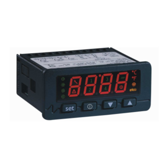
C-PRO NANO HARDWARE MANUAL 4 The C-PRO NANO user interface The display has four red-coloured digits (plus decimal points) and 16 icons of various colours; the keypad has 4 keys. C-PRO NANO Display Number of digits Colour Summer icon (air conditioning display) - Page 15 C-PRO NANO HARDWARE MANUAL Maintenance icon Colour Alarm icon Colour Icon 1 Colour Green Icon 2 Colour Green Icon 3 Colour Green Icon 4 Colour Green Heating element icon (air conditioning display) Colour Green Compressor icon (refrigeration display) On-Off icon...
-
Page 16: Pro Exp Micro I/O Expansion Units
C-PRO NANO HARDWARE MANUAL C-PRO EXP MICRO I/O expansion units The C-PRO EXP MICRO I/O expansion units allow expansion of the controllers I/O capacity. There are two types of expansion unit, one sealed in a case with 4 DIN modules, and another open mounted on a base with 4 DIN modules. -
Page 17: The C-Pro Exp Micro Wiring Layout
The C-PRO EXP MICRO expansion unit wiring layout is shown below, with the meanings of the inputs and outputs given in the tables. C-PRO EXP MICRO wiring diagram The C-PRO NANO and C-PRO EXP MICRO power supplies must be galvanically isolated from one another. Connector 1: Output relay connection Conn. - Page 18 C-PRO NANO HARDWARE MANUAL C1-12 COMMON DO6 Relay No.6 - common Connector 2: Connector for low voltage signals Conn. Abbrev. Description C2-1 12 V AC (Power) Device power supply (12 V AC/DC) C2-2 Not connected Not connected C2-3 Common analogue and digital inputs...
-
Page 19: C-Pro Exp Micro Dimensions/Installation
User terminals allow the control units to be controlled remotely (display and commands). There are two interface types, one panel-mounted, the other wall-mounted. The interface is connected to the special (powered) serial connector of the C-PRO NANO controllers. V LEDi... -
Page 20: Ledi Dimensions And Installation
Local panel interface dimensions Connections Local panel interface connections Connector CI1: Interface connector Conn. Abbrev. Description CI1-1 12 V DC Keypad power supply CI1-2 Common CI1-3 DATA EVCO powered serial port C-PRO NANO with V LEDi wiring diagram Page 20... - Page 21 C-PRO NANO HARDWARE MANUAL The user interface has a 7 segment, 4 digit display (plus decimal point), 6 icons, and the user mode is achieved using 4 keys. Display Number of digits Colour Summer icon Colour Winter icon Colour Compressor icon...
-
Page 22: Wall Dimensions And Installation
C-PRO NANO HARDWARE MANUAL 6.1.2 V WALL dimensions and installation For wall installation, use appropriate rawplugs and screws. Wall-mounted version - dimensions Connections 1 2 3 4 Wall-mounted version wiring diagram Page 22... - Page 23 1 m, the maximum length of cables connecting the C-PRO NANO and V WALL is 30 m) Make the C-PRO NANO – V WALL connection using a twisted-pair cable; ensure that the cable does not run along side any high voltage sections.
- Page 24 C-PRO NANO HARDWARE MANUAL The user interface has a 7 segment, 4 digit display (plus decimal point), 6 icons and the user mode is achieved using 4 keys. Display Number of digits Colour Led L0 Colour Led L1 Colour Led L2...
- Page 25 “V-VIEW” user interface (with a alfanumeric 4 x 20 characters LCD display) can be connected to the CAN port of the C-PRO NANO controller. On request a graphic 240 x 128 pixel LCD display (V-GRAPH) user interface is also available .
- Page 26 C-PRO NANO HARDWARE MANUAL The following table summarizes the keyboard button meaning: BUTTONS MAIN FUNCTION SECONDARY FUNCTION Predefined as UP Predefined as DOWN Predefined as LEFT Predefined as RIGHT Predefined as ESC Stand-By command Predefined as ENTER 1° programming level command...
- Page 27 C-PRO NANO HARDWARE MANUAL 6.2.1.2 V-VIEW wiring layout 6.2.1.3 V-VIEW specifications General specifications Safety standards references EN 60730-1 Purpose of the device To be integrated in equipment Electronic control device connections Plug-in terminal block 5mm pitch for conductors up to 2.5 mm Storage temperature limits -20T70 °C (@RH<90% non-condensing)
- Page 28 C-PRO NANO HARDWARE MANUAL Type CAN V2.0B not optoisolated Physical Layer 2 wires + common, ISO 11898 standard Baud rate (L max. = 10 m) Serial CAN Communication Baud rate (L max. = 5 m) Baud rate (L max. = 2 m) 125K Baud rate (L max.
-
Page 29: Evdfan1 Cut-Off Speed Regulator
The fan module is available as an open card version, and is mounted on a plastic base suitable for fitting on a DIN rail. 135 mm x 71 mm DIN rail fan module dimensions Connections C-PRO NANO with EVDFAN1 wiring diagram Page 29... - Page 30 The cut-off module allows the control of single-phase fans with a maximum current equal to 5 A. The fan module live feed must be the same as that feeding the controller. If the C-PRO NANO has a DC power supply, then it is not possible to control the fans using the EVDFAN1. Example:...
-
Page 31: Accessories For Supervision And Monitoring
C-PRO NANO HARDWARE MANUAL 6.4 Accessories for supervision and monitoring These modules allow the conversion of TTL signals to RS485 signals (with or without isolation) for supervision using the MODBUS protocol. The modules connect to the special 6 way AMP micro-match connector on the controller; this connector is shared with the parameter programming key and with the controller flash memory programming tools. - Page 32 C-PRO NANO HARDWARE MANUAL EVIF21TS7I connections Insulated interface wiring diagram Connector Conn. Abbrev. Description RS485+ RS485- shield COMMON Power supply 230 V AC Power supply 230 V AC Page 32...
-
Page 33: Programming Accessories
EVKEY 6.5.2 EVPROG programming kit The EVPROG programming kit allows downloading programs into the flash memory of the C-PRO NANO controller (even when the controller is not powered; in this case, it is necessary to use the EVPS power supply). - Page 34 7 CAN Connection C-PRO NANO can be connected to other controllers, to expansion modules and to one or more user interfaces using either local or wide CAN serial port. The CAN bus uses the ISO 11898 standard, a balanced two-wire communication very similar to the RS 485 standard.
- Page 35 C-PRO NANO HARDWARE MANUAL 7.1 Notes on the parameter of the controller relative to the CAN net configuration To log on the controller parameters configuration procedure relative to the analogic output act in the following way : Both for the remote or built-in user interface :...
- Page 36 C-PRO NANO HARDWARE MANUAL The main parameters of the CAN net are the following : • “My Node” (represents the data sender ID ) • “Network Node” (represents the receiver ID) • Baud rate (represent the data transmissions speed; initially it can be useful to let this value set at “Auto”;...
- Page 37 This document is the exclusive property of Evco, whereby any reproduction or distribution is strictly forbidden, unless expressly directly authorised by Evco. Evco assume no responsibility in relation to the characteristics, technical data and any possible errors reported in this document or deriving from the use of the same. Evco cannot be held responsible for any damage caused by failure to observe these warnings.
- Page 38 OVERSEAS OFFICES Control France 155 Rue Roger Salengro, 92370 Chaville Paris FRANCE Tel: 0033-1-41159740 Fax: 0033-1-41159739 control.france@wanadoo.fr Evco Latina Larrea, 390 San Isidoro, 1609 Buenos Aires ARGENTINA Tel: 0054-11-47351031 Tel: 0054-11-47351031 evcolatina@anykasrl.com.ar Evco Pacific 59 Premier Drive Campbellfield, 3061, Victoria Melbourne, AUSTRALIA...
Need help?
Do you have a question about the C-PRO NANO and is the answer not in the manual?
Questions and answers