
Subscribe to Our Youtube Channel
Related Manuals for Evco Vcolor 539 Series


Summary of Contents for Evco Vcolor 539 Series
- Page 1 EVCO S.p.A. Vcolor 539 M & L | Installer manual ver. 1.0 | Code 144VC539E104 Vcolor 539 M & L Controllers for food processing cabinets and rooms ENGLISH INSTALLER MANUAL ver. 1.0 CODE 144VC539E104 page...
- Page 2 EVCO S.p.A. Vcolor 539 M & L | Installer manual ver. 1.0 | Code 144VC539E104 Important Read this document carefully before installation and before using the device and take all the prescribed precautions. Keep this document with the device for future consultation.
-
Page 3: Table Of Contents
EVCO S.p.A. Vcolor 539 M & L | Installer manual ver. 1.0 | Code 144VC539E104 Index INTRODUCTION ............ 4 6.2.1 Start-up and interruption of an automatic cycle ..22 Product description ..........4 6.2.2 Setting/Making changes to an automatic cycle ..23 Table listing the models available, their main features 6.2.3... -
Page 4: Introduction
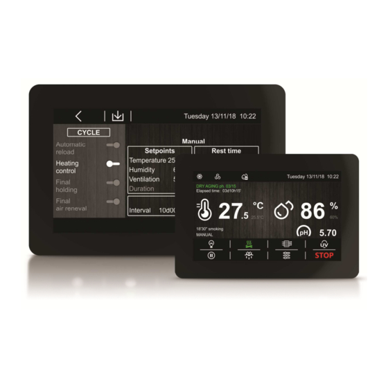
EVCO S.p.A. Vcolor 539 M & L | Installer manual ver. 1.0 | Code 144VC539E104 INTRODUCTION Product description Vcolor 539 is a split controller with a capacitive TFT touch-screen colour graphic display (5” or 7") for flush panel fitting and total management of food processing cabinets or rooms for different types of products such as meat, charcuterie and cheese. - Page 5 EVCO S.p.A. Vcolor 539 M & L | Installer manual ver. 1.0 | Code 144VC539E104 Table listing the models available, their main features and purchasing codes The table below lists the models available. Vcolor 539 M Vcolor 539 L EVC20P52N9XXX10...
- Page 6 Vcolor 539 M (control module + 5-inch user interface kit) EVCMC539N9E Vcolor 539L (control module + 7-inch user interface kit) EVCLC539N9E Purchasing codes EVC20P52N9XXX10 (optional 4 relay expansion) EVC20P52N9XXX10 EVHTP500 (optional temperature/humidity probe) EVHTP500 For more models contact the EVCO sales network. page...
-
Page 7: Measurements And Installation
EVCO S.p.A. Vcolor 539 M & L | Installer manual ver. 1.0 | Code 144VC539E104 MEASUREMENTS AND INSTALLATION Vcolor 539 M user interface measurements The figure below shows the measurements of the 5-inch user interface; measurements are expressed in mm (inches). -
Page 8: User Interface Installation
EVCO S.p.A. Vcolor 539 M & L | Installer manual ver. 1.0 | Code 144VC539E104 User interface installation The figure below shows the installation of the user interface. The user interface installed from behind using threaded studs enables it to be placed flush with the panel thus making it fit perfectly with the design of the unit. -
Page 9: Expansion Measurements Evc20P52N9Xxx10
EVCO S.p.A. Vcolor 539 M & L | Installer manual ver. 1.0 | Code 144VC539E104 Expansion measurements EVC20P52N9XXX10 The figure below shows the measurements of the 4 relay expansion. Installation precautions - Ensure that the working conditions for the device (operating temperature, humidity, etc.) are within the set limits. See the section 14 “TECHNICAL SPECIFICATIONS”. -
Page 10: Vcolor 539M Electrical Connection
EVCO S.p.A. Vcolor 539 M & L | Installer manual ver. 1.0 | Code 144VC539E104 Vcolor 539M electrical connection The diagram below shows the Vcolor 539 M electrical connection. page... -
Page 11: Vcolor 539L Electrical Connection
EVCO S.p.A. Vcolor 539 M & L | Installer manual ver. 1.0 | Code 144VC539E104 Vcolor 539L electrical connection The diagram below shows the Vcolor 539 L electrical connection. page... -
Page 12: First-Time Use
CONNECTION”. Connect the power supply to the device:if parameter E9 is set at 1 (default), the device will show the EVCO splash screen for 10 seconds; if the parameter is set at 0, a system loading screen will be shown:... -
Page 13: Navigation
EVCO S.p.A. Vcolor 539 M & L | Installer manual ver. 1.0 | Code 144VC539E104 NAVIGATION Initial information Navigating the menus is intuitive, based on touch technology. To enter into a procedure, touch the menu or the corresponding icon. To exit the procedure and, in general, to return to the previous level, press the Back key. -
Page 14: Run Screen
EVCO S.p.A. Vcolor 539 M & L | Installer manual ver. 1.0 | Code 144VC539E104 Run screen Once a manual or automatic cycle has been started up, the Run screen will appear for the type of cycle selected. MANUAL AUTOMATIC 4.3.1... -
Page 15: Function Keys
EVCO S.p.A. Vcolor 539 M & L | Installer manual ver. 1.0 | Code 144VC539E104 4.3.2 Function keys While a manual or automatic cycle is being run, the lower part of the screen displays the function keys, which are as follows. -
Page 16: Settings Screen
EVCO S.p.A. Vcolor 539 M & L | Installer manual ver. 1.0 | Code 144VC539E104 Settings screen The settings key on the On/Stand-by screen grants access to the Set-up screen with the relevant function menu (for the INPUTS/OUTPUTS STATUS function, data are only displayed). To access the various procedures, touch the screen near the information/function required. -
Page 17: An Overview Of The Functions
EVCO S.p.A. Vcolor 539 M & L | Installer manual ver. 1.0 | Code 144VC539E104 AN OVERVIEW OF THE FUNCTIONS Automatic and manual cycles The controller provides complete control for food processing cabinets or rooms for different types of products such as meat, charcuterie, cheese and other types of product. -
Page 18: Management Of Product Rest Intervals
EVCO S.p.A. Vcolor 539 M & L | Installer manual ver. 1.0 | Code 144VC539E104 If the user also wishes to deactivate the MANUAL air change, just set the air change duration to OFF (the equivalent of 0) for the desired phase. -
Page 19: Final Air Change
EVCO S.p.A. Vcolor 539 M & L | Installer manual ver. 1.0 | Code 144VC539E104 5.3.4 Final air change By enabling/disabling the "Final air change” function, the user decides if the equipment must carry out an air change cycle or not at the end of the final phase of the cycle in progress. -
Page 20: Manual Rest Cycle
EVCO S.p.A. Vcolor 539 M & L | Installer manual ver. 1.0 | Code 144VC539E104 white icon key = function disabled green icon key = function enabled and output activated orange icon key = function enabled and output deactivated 5.4.3 Manual rest cycle The operation of this cycle is described in the section "Management of product rest intervals". -
Page 21: Main Functions
EVCO S.p.A. Vcolor 539 M & L | Installer manual ver. 1.0 | Code 144VC539E104 MAIN FUNCTIONS Manual cycle This area grants access to a manual product conservation/aging cycle. First a setting screen for the values will be displayed (the last values set for a manual cycle will be given) and, once they have been confirmed, the manual cycle will start. -
Page 22: Automatic Cycle
EVCO S.p.A. Vcolor 539 M & L | Installer manual ver. 1.0 | Code 144VC539E104 Automatic cycle 6.2.1 Start-up and interruption of an automatic cycle This area grants access to the following screen where a complete aging cycle can be set, phase by phase:... -
Page 23: Setting/Making Changes To An Automatic Cycle
EVCO S.p.A. Vcolor 539 M & L | Installer manual ver. 1.0 | Code 144VC539E104 6.2.2 Setting/Making changes to an automatic cycle Before starting up a cycle, it is possible to consult and modify the settings of each of the stages in the aging cycle. -
Page 24: Regulations
EVCO S.p.A. Vcolor 539 M & L | Installer manual ver. 1.0 | Code 144VC539E104 REGULATIONS Temperature regulation Temperature regulation for all phases of the equipment is in the neutral zone in which two relative values are set one above and one below the temperature setpoint, thus creating a zone inside which the loads for heating and cooling are not activated. -
Page 25: Humidity Regulation
EVCO S.p.A. Vcolor 539 M & L | Installer manual ver. 1.0 | Code 144VC539E104 Humidity regulation In all phases where this is required, the humidity is regulated with a humidity transducer enabled in the neutral zone in which two values are set, one above and one below the humidity setpoint, thus creating a zone inside which the loads for humidification and dehumidification are not activated. -
Page 26: Dehumidification Management
EVCO S.p.A. Vcolor 539 M & L | Installer manual ver. 1.0 | Code 144VC539E104 If parameter E12 is set at 1, the generator output will only be active when the humidity falls below the neutral zone value (set by parameter rU9) beyond the threshold set by rU8 (humidification differential). -
Page 27: Load Management
EVCO S.p.A. Vcolor 539 M & L | Installer manual ver. 1.0 | Code 144VC539E104 LOAD MANAGEMENT Compressor management Activation of the compressor depends on the length of the delay between two switch-ons (parameter C1), on the minimum duration of the compressor-off time (parameter C2), on the delayed switch-on of the compressor from the device power-on (parameter C0) and on the minimum duration of the compressor-on time (parameter C3). -
Page 28: Defrost Management
EVCO S.p.A. Vcolor 539 M & L | Installer manual ver. 1.0 | Code 144VC539E104 To adapt the phase-cutting regulation (T.D.F.) to all types of 230 VAC single-phase motors, a manual evaporator fan calibration procedure is recommended. Set F23 at 0% and F24 at 100%. -
Page 29: Dehumidification Management
EVCO S.p.A. Vcolor 539 M & L | Installer manual ver. 1.0 | Code 144VC539E104 8.7.3 Managing the humidifier output with a transducer and an instant generation humidifier (rU0 = 0, E12 = 1) The humidifier output is activated when the humidity value inside the cabinet falls below the neutral zone value (rU9) beyond the threshold set by the humidification differential (rU8) performing off/on cycles, the duration being set by parameters rU15 and rU16. -
Page 30: Smoker Management
EVCO S.p.A. Vcolor 539 M & L | Installer manual ver. 1.0 | Code 144VC539E104 If the aging cycle goes into the rest or air change phase, the sterilisation/oxygenation cycle is paused. If the door is opened, if there is a defrosting cycle or if the evaporator fan is deactivated, the sterilisation cycle will be SUSPENDED and will resume when the evaporator fan is reactivated. - Page 31 EVCO S.p.A. Vcolor 539 M & L | Installer manual ver. 1.0 | Code 144VC539E104 ON during a special air change cycle OFF during a special rest cycle OFF during a pause between two phases (new parameter to insert) OFF when both the temperature and humidity values are within the neutral zone value.
-
Page 32: Usb Port Management
EVCO S.p.A. Vcolor 539 M & L | Installer manual ver. 1.0 | Code 144VC539E104 10 USB PORT MANAGEMENT The USB port provides the following functions: download to a USB flash drive the data relating to the cycles performed (HACCP history) -
Page 33: Parameters
EVCO S.p.A. Vcolor 539 M & L | Installer manual ver. 1.0 | Code 144VC539E104 11 PARAMETERS The table below describes the configuration parameters of the device. Par. Unit Default Analogue inputs °C cabinet probe offset °C evaporator probe offset °C... - Page 34 EVCO S.p.A. Vcolor 539 M & L | Installer manual ver. 1.0 | Code 144VC539E104 heater switch-on time within the rH6 cycle time duration pause at beginning of phase +Par. Unit Default Humidity regulator humidity management mode: 0 = with humidity probe 4 -20 mA...
- Page 35 EVCO S.p.A. Vcolor 539 M & L | Installer manual ver. 1.0 | Code 144VC539E104 type of defrost = electrical (during defrosting the compressor is switched off, the defrost output is activated and the evaporator fan switched off). - - - -...
- Page 36 EVCO S.p.A. Vcolor 539 M & L | Installer manual ver. 1.0 | Code 144VC539E104 continuous function fan speed during the dehumidification phase fan stop after the drip phase evaporator fan switch-off delay from main load switch-off evaporator fan cycle time with compressor switched off (applies both during normal operation and during a product rest phase).
- Page 37 EVCO S.p.A. Vcolor 539 M & L | Installer manual ver. 1.0 | Code 144VC539E104 effect caused by activation of the low pressure input no effect 1 =ALARM The compressor and evaporator fan are switched off 2 =PUMP-DOWN AND ALARM MANAGEMENT While the compressor is...
- Page 38 - - - - even Par. Unit Default Other password to unlock screen saver - - - = not enabled inactivity period for enabling screen-saver = not enabled display EVCO splash screen at power-on - - - - neutral screen page...
- Page 39 EVCO S.p.A. Vcolor 539 M & L | Installer manual ver. 1.0 | Code 144VC539E104 EVCO splash screen duration of buzzer at end type of humidifier - - - - humidifier with steamer humidifier with instant generation duration of “cycle completed” display...
-
Page 40: Alarms
EVCO S.p.A. Vcolor 539 M & L | Installer manual ver. 1.0 | Code 144VC539E104 12 ALARMS An alarm event is signalled by a prolonged buzzer sound and it can be seen when the icon appears on the upper part of the screen. - Page 41 EVCO S.p.A. Vcolor 539 M & L | Installer manual ver. 1.0 | Code 144VC539E104 - all loads are deactivated Power failure during a cycle run alarm (if the power failure is greater than P5) POWER FAILURE To correct: - check the device-power supply connection Condenser overheat alarm.
- Page 42 EVCO S.p.A. Vcolor 539 M & L | Installer manual ver. 1.0 | Code 144VC539E104 Main consequences if parameter rU0 is set to 0: if the error happens during “stand-by”, it will not be possible to start up humidity management cycles if the error happens during a humidity control cycle, the cycle will be interrupted.
-
Page 43: Accessories
EVCO S.p.A. Vcolor 539 M & L | Installer manual ver. 1.0 | Code 144VC539E104 13 ACCESSORIES 13.1 Non-optoisolated RS-485/USB serial interface The interface enables the device to be connected to the Parameters Manager set-up software system. 13.2 USB plug for panel installation The plug makes the USB communications port of the device more accessible. -
Page 44: Technical Specifications
EVCO S.p.A. Vcolor 539 M & L | Installer manual ver. 1.0 | Code 144VC539E104 14 TECHNICAL SPECIFICATIONS 14.1 Technical specifications Purpose of the control device: function controller. Construction of the control device: built-in electronic device. user interface control module Housing: open frame board behind glass. - Page 45 Clock battery charging time: 24 h (the battery is charged by the power supply of the device). 5 inputs, 3 of which for PTC/NTC inputs (cabinet probe, evaporator probe and condenser probe), 1 for 4-20 mA input (humidity or pH probe), 1 for EVCO humidity probe EVHTP500 PTC type analogue inputs Type of sensor: KTY 81-121 (990 Ohm @ 25 °C, 77 °F).
- Page 46 EVCO S.p.A. Vcolor 539 M & L | Installer manual ver. 1.0 | Code 144VC539E104 1 for PWM signal (for phase cutting speed regulator for single-phase EVDFAN1 Analogue outputs: fans). 9 outputs (electro-mechanical relays): - 1 16 A res. @ 250 VAC type SPST (K1) configurable - 1 8 A res.
- Page 47 Intellectual Property Rights Code (CPI). EVCO imposes an absolute ban on the full or partial reproduction and disclosure of the content other than with the express approval of EVCO. The customer (manufacturer, installer or end user) assumes all responsibility for the configuration of the device. EVCO...
- Page 48 EVCO S.p.A. Vcolor 539 M & L | Installer manual ver. 1.0 | Code 144VC539E104 EVCO S.p.A. Via Feltre 81, 32036 Sedico Belluno ITALY Tel. +39 0437/8422 | Fax +39 0437/83648 info@evco.it | www.evco.it page...
Need help?
Do you have a question about the Vcolor 539 Series and is the answer not in the manual?
Questions and answers