Table of Contents
Advertisement
Quick Links
EVCO S.p.A.
Vcolor 819 | Installer manual ver. 1.0 | Code 144VC819I104
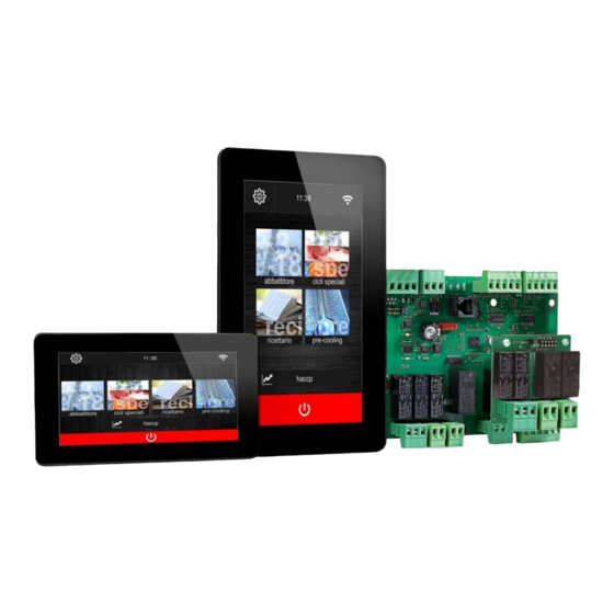
Vcolor 819
Controllers for top-class blast chillers, in split
version that can be built into the unit, with 5- or 7-
inch colour TFT touch-screen graphic display in
either vertical or horizontal format
ENGLISH
INSTALLER MANUAL ver. 1.0
CODE 144VC819I104
page
1 of 84
Advertisement
Table of Contents

Related Manuals for Evco Vcolor 819


Summary of Contents for Evco Vcolor 819
- Page 1 EVCO S.p.A. Vcolor 819 | Installer manual ver. 1.0 | Code 144VC819I104 Vcolor 819 Controllers for top-class blast chillers, in split version that can be built into the unit, with 5- or 7- inch colour TFT touch-screen graphic display in...
- Page 2 EVCO S.p.A. Vcolor 819 | Installer manual ver. 1.0 | Code 144VC819I104 Important Read this document carefully before installation and before using the device and take all the prescribed precautions. Keep this document with the device for future consultation. The following symbols are used in this document: indicates a suggestion indicates a warning.
-
Page 3: Table Of Contents
EVCO S.p.A. Vcolor 819 | Installer manual ver. 1.0 | Code 144VC819I104 Index INTRODUCTION ........................... 6 Introduction ............................6 Main features of the models available and their purchasing codes .............. 7 DESCRIPTION ............................ 10 User interface description ........................10 Control module description ........................12 MEASUREMENTS AND INSTALLATION .................... - Page 4 EVCO S.p.A. Vcolor 819 | Installer manual ver. 1.0 | Code 144VC819I104 Fish sanitation ........................... 35 Thawing ............................37 Defrosting ............................39 Ice cream hardening........................... 40 Cabinet sterilisation ..........................41 Heating the needle probe ........................41 Drying .............................. 42 Proofing ............................43 8.8.1...
- Page 5 EVCO S.p.A. Vcolor 819 | Installer manual ver. 1.0 | Code 144VC819I104 15.1 Alarms ............................72 15.2 HACCP alarms ..........................77 ACCESSORIES ........................... 78 16.1 EVC20P52N9XXX10 - Multi-functional module ..................78 16.2 ECTSFD004 - 230 VAC/12 VAC 20 VA safety transformer ..............78 16.3...
-
Page 6: Introduction
EVCO S.p.A. Vcolor 819 | Installer manual ver. 1.0 | Code 144VC819I104 INTRODUCTION Introduction The Vcolor 819 series is a range of stylish controllers for managing top-class blast chillers. Available in split version, the user interface can be built into the unit mechanically for optimum aesthetic effect. -
Page 7: Main Features Of The Models Available And Their Purchasing Codes
EVCO S.p.A. Vcolor 819 | Installer manual ver. 1.0 | Code 144VC819I104 Main features of the models available and their purchasing codes The table below shows the main features of the models available and the purchasing codes. AVAILABLE MODELS AND KIT... - Page 8 EVCO S.p.A. Vcolor 819 | Installer manual ver. 1.0 | Code 144VC819I104 AVAILABLE MODELS AND KIT OPTIONS PURCHASING CODES MAIN FEATURES multi-functional Vcolor 819M (5") Vcolor 819L (7") module Vertical display EVCMC819P9E EVCLC819P9E EVC20P52N9XXX10 Horizontal display EVCMC829P9E EVCLC829P9E Digital outputs electro-mechanical relays;...
- Page 9 UV lamp, needle probe heater or alarm. Optional models Models with Wi-Fi connectivity. For more information contact the EVCO sales network. page 9 of 84...
-
Page 10: Description
EVCO S.p.A. Vcolor 819 | Installer manual ver. 1.0 | Code 144VC819I104 DESCRIPTION User interface description The diagram below shows the front view of the user interface in the vertical format The diagram below shows the front view of the user interface in the horizontal format. - Page 11 EVCO S.p.A. Vcolor 819 | Installer manual ver. 1.0 | Code 144VC819I104 The diagram below shows the intended use of the user interface connectors. PART DESCRIPTION USB port RS-485 MODBUS port dip switch for the termination resistor for the RS-485 MODBUS port...
-
Page 12: Control Module Description
EVCO S.p.A. Vcolor 819 | Installer manual ver. 1.0 | Code 144VC819I104 Control module description The diagram below shows the intended use of the control module connectors. PART DESCRIPTION control module power supply evaporator fan and condenser fan relay defrost relay... -
Page 13: Measurements And Installation
EVCO S.p.A. Vcolor 819 | Installer manual ver. 1.0 | Code 144VC819I104 MEASUREMENTS AND INSTALLATION Vcolor 819M user interface measurements The picture below shows the measurements of the 5-inch user interface; measurements are expressed in mm (inches). Vcolor 819L user interface measurements The picture below shows the measurements of the 7-inch user interface;... -
Page 14: Control Module Measurements
EVCO S.p.A. Vcolor 819 | Installer manual ver. 1.0 | Code 144VC819I104 Control module measurements The picture below shows the measurements of the Vcolor 819 control module; measurements are expressed in mm (inches). Multi-functional module measurements The picture below shows the measurements of the Vcolor 819 multi-functional module; measurements are expressed in mm (inches). -
Page 15: User Interface Installation
EVCO S.p.A. Vcolor 819 | Installer manual ver. 1.0 | Code 144VC819I104 User interface installation Installed from behind using threaded studs to guarantee flush fitting. Control and multi-functional module installation On a flat surface with spacers. Installation precautions Ensure that the working conditions for the device (operating temperature, humidity, etc.) are within the set limits. -
Page 16: Electrical Connection
EVCO S.p.A. Vcolor 819 | Installer manual ver. 1.0 | Code 144VC819I104 ELECTRICAL CONNECTION Electrical connection of Vcolor 819M The picture below shows the electrical connection of the controller with 5-inch display. page 16 of 84... -
Page 17: Electrical Connection Of Vcolor 819L
See section 17 TECHNICAL SPECIFICATIONS. Disconnect the device from the power supply before doing any type of maintenance. Do not use the device as safety device. For repairs and for further information on the device, contact the EVCO sales network. page 17 of 84... -
Page 18: User Interface
Initial switch-on Connect the power supply to the device: if parameter E9 is set at 1, the device will show the EVCO splash screen for 10 seconds; if the parameter is set at 0, a system loading screen will be shown:... -
Page 19: Switching The Device On And Off
EVCO S.p.A. Vcolor 819 | Installer manual ver. 1.0 | Code 144VC819I104 Once loading is complete, the device will display the mode it was in before being powered down: On/Stand-by screen, press the central area to move to the Home screen;... -
Page 20: Lock/Unlock Keypad
EVCO S.p.A. Vcolor 819 | Installer manual ver. 1.0 | Code 144VC819I104 Lock/unlock keypad The keypad can be locked by setting parameter E7 to 1, locking the keypad after the period of inactivity set by parameter E8. If the keypad is locked, a pop-up will appear when it is touched indicating that it is locked and how to unlock it. It can be unlocked by dragging a finger to the right. -
Page 21: Function Modes
EVCO S.p.A. Vcolor 819 | Installer manual ver. 1.0 | Code 144VC819I104 FUNCTION MODES Initial information on operating cycles The device is capable of operating in the following modes: temperature controlled blast chilling and conservation hard temperature controlled blast chilling and conservation... -
Page 22: Selecting The Operating Mode
EVCO S.p.A. Vcolor 819 | Installer manual ver. 1.0 | Code 144VC819I104 Selecting the operating mode All the operating functions can be accessed from the Home screen by selecting the desired area. Enables the blast chilling mode in which it is possible to select/set a standard blast chilling/blast-freezing cycle, a multineedle probe or multi-timer cycle, see chapter 7. -
Page 23: Blast-Chilling Mode
EVCO S.p.A. Vcolor 819 | Installer manual ver. 1.0 | Code 144VC819I104 BLAST-CHILLING MODE Press on this area to open the screen shown below. Now one of the areas shown can be selected: blast chilling, blast-freezing, continuous cycle and customized cycle, details below. -
Page 24: Blast Chilling/Blast-Freezing And Conservation
EVCO S.p.A. Vcolor 819 | Installer manual ver. 1.0 | Code 144VC819I104 Blast chilling/blast-freezing and conservation Pressing on one of these areas enables a blast chilling or blast-freezing cycle to be set. The following screen opens and key lights up blue. If the needle probe is being used and there is no error, the cycle always defaults to temperature control. - Page 25 EVCO S.p.A. Vcolor 819 | Installer manual ver. 1.0 | Code 144VC819I104 Press area to save the program just set, or press area to start up the cycle. If it is a temperature controlled cycle, a test will be performed to check that the needle probe has been correctly inserted in the food item to be blast chilled.
-
Page 26: Hard Blast Chilling/Soft Blast-Freezing And Conservation
EVCO S.p.A. Vcolor 819 | Installer manual ver. 1.0 | Code 144VC819I104 Hard blast chilling/soft blast-freezing and conservation It is possible to select a hard blast chilling/soft blast-freezing cycle on the blast chilling/blast-freezing settings screen by pressing area . Before selecting this mode, make sure the type of cycle (temperature or time controlled) has been set. -
Page 27: Multineedle Probe Mode
EVCO S.p.A. Vcolor 819 | Installer manual ver. 1.0 | Code 144VC819I104 7.3.1 Multineedle probe mode The continuous cycle using multineedle probes can be run provided the parameter for the type of needle probe has been correctly set (P3=2). The controller can manage up to three needle probes, using parameter P9 to set these up. -
Page 28: Customized Cycle
EVCO S.p.A. Vcolor 819 | Installer manual ver. 1.0 | Code 144VC819I104 Customized cycle The customized mode makes it possible to set up a cycle consisting of a maximum of 4 phases (3 blast chilling and 1 conservation) and these can be temperature or time controlled or a mixture of both. -
Page 29: Setting The Set Points
EVCO S.p.A. Vcolor 819 | Installer manual ver. 1.0 | Code 144VC819I104 Setting the set points 7.5.1 Setting the cabinet temperature set point When selecting a continuous or customized blast chilling or blast-freezing cycle, the pre-set cabinet temperature, product temperature, time and fan speed values when the parameters were set are loaded. These can be modified by the user within the permitted range for the parameters. -
Page 30: Setting The Fan Speed
EVCO S.p.A. Vcolor 819 | Installer manual ver. 1.0 | Code 144VC819I104 7.5.4 Setting the fan speed To modify this, press area for the fan speed and the screen shown below will open. Set the desired value pressing the key. Once set-up is complete press the... -
Page 31: Needle Probe Insertion Test
EVCO S.p.A. Vcolor 819 | Installer manual ver. 1.0 | Code 144VC819I104 The screen shows a summary of the features of the cycle in progress and a chart with the various values required (cabinet temperature and product temperature for temperature controlled cycles and cabinet temperature and time period for time controlled cycles). -
Page 32: Cycle End
EVCO S.p.A. Vcolor 819 | Installer manual ver. 1.0 | Code 144VC819I104 7.6.3 Cycle end If the temperature controlled blast chilling/blast-freezing cycle is successfully completed, in which the centre of the product reaches the required temperature in the allotted time, the device moves on automatically to the conservation phase, with the following screen appearing. - Page 33 EVCO S.p.A. Vcolor 819 | Installer manual ver. 1.0 | Code 144VC819I104 page 33 of 84...
-
Page 34: Special Cycles Mode
EVCO S.p.A. Vcolor 819 | Installer manual ver. 1.0 | Code 144VC819I104 SPECIAL CYCLES MODE Press this area on the Home page to open the screen shown below. This screen grants access to further functions, some always present, others that can be activated by setting the parameter. -
Page 35: Fish Sanitation
EVCO S.p.A. Vcolor 819 | Installer manual ver. 1.0 | Code 144VC819I104 Pressing this area enables selection of a needle probe heating cycle (a function activated by parameter if at least one needle probe is being used); see section 8.6. - Page 36 EVCO S.p.A. Vcolor 819 | Installer manual ver. 1.0 | Code 144VC819I104 While a sanitation cycle is in progress the device will show the temperature to end blast chilling, the working set point during blast chilling and the duration of the holding phase.
-
Page 37: Thawing
EVCO S.p.A. Vcolor 819 | Installer manual ver. 1.0 | Code 144VC819I104 Thawing Pressing this area enables selection of a thawing cycle, managed according to the load of product to be thawed, in compliance with the maximum quantity stated by the manufacturer. - Page 38 EVCO S.p.A. Vcolor 819 | Installer manual ver. 1.0 | Code 144VC819I104 Five parameters are used to manage the ventilation, one for each phase, setting the fan speed independently of the load. These parameters are: F29, F30, F31, F32, F33.
-
Page 39: Defrosting
EVCO S.p.A. Vcolor 819 | Installer manual ver. 1.0 | Code 144VC819I104 Defrosting Pressing this area enables selection of a manual defrosting cycle, which is started up by pressing area When the cycle starts up the following page is displayed. -
Page 40: Ice Cream Hardening
EVCO S.p.A. Vcolor 819 | Installer manual ver. 1.0 | Code 144VC819I104 Defrosting finishes when the evaporator temperature is above the value of parameter d2 or if the temperature has not been reached within the required time set by parameter d3. In this case there is an alarm signal. -
Page 41: Cabinet Sterilisation
EVCO S.p.A. Vcolor 819 | Installer manual ver. 1.0 | Code 144VC819I104 Cabinet sterilisation Pressing this area enables selection of a sterilisation cycle. This function can be activated by parameter and can only be used if u1=1. If the needle probe heating function has also been enabled, the sterilisation icon is shown if the temperature recorded by the needle probe is above 0°C . -
Page 42: Drying
EVCO S.p.A. Vcolor 819 | Installer manual ver. 1.0 | Code 144VC819I104 The function can be activated by parameter and can only be used if u1=2 or u3=1. If cabinet sterilisation has also been enabled, the needle probe heating icon is shown if the temperature recorded by the needle probe is above 0°C . -
Page 43: Proofing
EVCO S.p.A. Vcolor 819 | Installer manual ver. 1.0 | Code 144VC819I104 Proofing Pressing this area enables selection of a proofing cycle. This function can only be enabled if an expansion has been set (parameter E12=1). 8.8.1 Description of proofing The controller provides complete control for retarding-proofing cabinets for bread or pastry by managing the complete dough retarding-proofing cycle automatically. - Page 44 EVCO S.p.A. Vcolor 819 | Installer manual ver. 1.0 | Code 144VC819I104 By default the controller always loads the pre-set values for the various phases as shown in the table below (these can be personalised via the manufacturer’s parameters). The settings for the cycle can be modified before it is started up using the special menus and once the key has been pressed, the proofing cycle starts up.
-
Page 45: Slow Cooking
EVCO S.p.A. Vcolor 819 | Installer manual ver. 1.0 | Code 144VC819I104 Slow cooking Pressing this area enables selection of a slow cooking cycle. This function can only be enabled if an expansion has been set (parameter E12 = 1). -
Page 46: Recipe Book Mode
EVCO S.p.A. Vcolor 819 | Installer manual ver. 1.0 | Code 144VC819I104 RECIPE BOOK MODE Pressing this area on the Home page opens the following screen. This screen grants access to a recipe book divided into four categories: blast chilling, blast-freezing, proofing and slow cooking. - Page 47 EVCO S.p.A. Vcolor 819 | Installer manual ver. 1.0 | Code 144VC819I104 The screen below shows an example of a blast chilling recipe book, showing the icons for the 6 recipes pre-set by the manufacturer. Pressing area enables selection of a further list of personalised recipes saved by the user.
-
Page 48: Pre-Set Blast Chilling Recipes
EVCO S.p.A. Vcolor 819 | Installer manual ver. 1.0 | Code 144VC819I104 Pre-set blast chilling recipes Phase 1 Cabinet setting -25°C Needle probe setting 20°C Ventilation setting Phase 2 Cabinet setting -5°C Needle probe setting 3°C Ventilation setting Conservation Cabinet setting 5°C... -
Page 49: Pre-Set Blast-Freezing Recipes
EVCO S.p.A. Vcolor 819 | Installer manual ver. 1.0 | Code 144VC819I104 Phase 1 Cabinet setting -5°C Duration setting 90 min Ventilation setting Conservation Cabinet setting 2°C Ventilation setting Phase 1 Cabinet setting -5°C Duration setting 90 min Ventilation setting... -
Page 50: Over-Writing A Recipe
EVCO S.p.A. Vcolor 819 | Installer manual ver. 1.0 | Code 144VC819I104 Over-writing a recipe It is possible to over-write a recipe but not to delete it. When a recipe is being over-written the screen below will be displayed requesting confirmation of the choice. -
Page 51: Pre-Cooling Mode
EVCO S.p.A. Vcolor 819 | Installer manual ver. 1.0 | Code 144VC819I104 PRE-COOLING MODE Pressing this area on the Home page enables selection of a pre-cooling cycle. This cycle is similar to a normal blast chilling cycle and it may precede all operating cycles. -
Page 52: Adjustments
EVCO S.p.A. Vcolor 819 | Installer manual ver. 1.0 | Code 144VC819I104 ADJUSTMENTS 11.1 Door frame heating output This function is activated automatically when the board is in “on” or “run” mode and the cabinet temperature falls below the value set by parameter u5 minus the fixed hysteresis of 2°C (4°F). The output is deactivated when the temperature rises above the u5 setting. -
Page 53: Pump Down Solenoid Valve Management
EVCO S.p.A. Vcolor 819 | Installer manual ver. 1.0 | Code 144VC819I104 11.3 Pump down solenoid valve management The pump down solenoid valve is activated in parallel with the compressor. When the compressor is set to switch off, the pump down solenoid valve is deactivated first and after the number of seconds set by the u12 parameter, the compressor is deactivated. -
Page 54: Condenser Fan Management
EVCO S.p.A. Vcolor 819 | Installer manual ver. 1.0 | Code 144VC819I104 Slow cooking and holding During slow cooking, the fans will be managed according to parameter F50. If the parameter is set to 0 (default), they will always be active. If set to 1, they will be active when heating elements are ON, while they will be switched on the basis of ON-OFF cycles (parameters F51 and F52) when the heating elements are OFF. -
Page 55: Cabinet Sterilisation Management
EVCO S.p.A. Vcolor 819 | Installer manual ver. 1.0 | Code 144VC819I104 11.8 Cabinet sterilisation management This function is present if parameter E12 is set to 1. During a sterilisation cycle the door must be closed and the output activates for the time period set by parameter u6. -
Page 56: Settings
EVCO S.p.A. Vcolor 819 | Installer manual ver. 1.0 | Code 144VC819I104 SETTINGS The SETTINGS are accessed by pressing area the Home page. The page displays the following menu: service set-up select language configure Wi-Fi. 12.1 Service The SERVICE area displays the list of available functions, as follows. -
Page 57: Configure Wi-Fi
EVCO S.p.A. Vcolor 819 | Installer manual ver. 1.0 | Code 144VC819I104 Access to the network 12.4 Configure Wi-Fi 12.4.1 Initial information Models with built-in Wi-fi connectivity enable the controller to be connected to the CloudEvolution supervision system which is accessible from a laptop, tablet and smartphone using an ordinary browser without the need to install any additional software. -
Page 58: Connection To Cloud Evolution
EVCO S.p.A. Vcolor 819 | Installer manual ver. 1.0 | Code 144VC819I104 12.4.3 Connection Cloud 12.4.4 Connection diagnostics From the Home page it is possible to view the Wi- Evolution Fi/CloudEvolution network status, indicated by the To access this system proceed as follows. -
Page 59: Using The Usb Port
EVCO S.p.A. Vcolor 819 | Installer manual ver. 1.0 | Code 144VC819I104 USING THE USB PORT 13.1 Initial information 13.2 Download/upload recipes The USB port makes possible the following operations. download and upload recipes After connecting device selecting download upload configuration “download recipes”... -
Page 60: Download/Upload Parameters
EVCO S.p.A. Vcolor 819 | Installer manual ver. 1.0 | Code 144VC819I104 13.3 Download/upload 13.4 Download HACCP parameters data After connecting device selecting After connecting device selecting “download parameters” or “upload parameters”, the “download HACCP data”, a CSV (comma separated... -
Page 61: List Of Configuration Parameters
EVCO S.p.A. Vcolor 819 | Installer manual ver. 1.0 | Code 144VC819I104 LIST OF CONFIGURATION PARAMETERS The following table gives the meaning of the configuration parameters. N.B. Because some functions are managed according to the value set for some parameters, ensure these are set correctly and consistently. - Page 62 EVCO S.p.A. Vcolor 819 | Installer manual ver. 1.0 | Code 144VC819I104 PAR. DEFAULT MIN. MAX. U.M. MAIN REGULATOR Cabinet set point differential in blast chilling, blast-freezing, °C/°F sanitation, ice cream hardening and customized cycles. Duration of time controlled blast chilling...
- Page 63 EVCO S.p.A. Vcolor 819 | Installer manual ver. 1.0 | Code 144VC819I104 Product temperature set point for the first phase of sanitation °C/°F and cabinet temperature set point for the second phase of sanitation. Duration of second sanitation phase. °C/°F Cabinet temperature set point for the third phase of sanitation.
- Page 64 EVCO S.p.A. Vcolor 819 | Installer manual ver. 1.0 | Code 144VC819I104 °C/°F Cabinet temperature set point for holding phase. °C/°F Neutral zone relative threshold (heating) for all proofing phases. Blast chilling phase duration (for proofing cycle). Re-awakening phase duration.
- Page 65 EVCO S.p.A. Vcolor 819 | Installer manual ver. 1.0 | Code 144VC819I104 PAR. DEFAULT MIN. MAX. U.M. COMPRESSOR PROTECTION Minimum time between restoration of power supply after a power failure happening during operating cycle compressor switch-on. Minimum time between two consecutive compressor switch-ons.
- Page 66 EVCO S.p.A. Vcolor 819 | Installer manual ver. 1.0 | Code 144VC819I104 If the evaporator probe is not present (P4=0), it sets the defrost duration. If the evaporator probe is present (P4=1), it sets the maximum defrost duration. See also parameter d2 = defrost is never activated.
- Page 67 EVCO S.p.A. Vcolor 819 | Installer manual ver. 1.0 | Code 144VC819I104 Duration of buzzer activation on completion of blast chilling and blast-freezing. Duration of alarm buzzer activation. PAR. DEFAULT MIN. MAX. U.M. EVAPORATOR AND CONDENSER FANS The evaporator temperature above which the evaporator fan...
- Page 68 EVCO S.p.A. Vcolor 819 | Installer manual ver. 1.0 | Code 144VC819I104 - - - - Fan speed during customized blast chilling. - - - - Fan speed during customized conservation. - - - - Fan speed during slow cooking.
- Page 69 EVCO S.p.A. Vcolor 819 | Installer manual ver. 1.0 | Code 144VC819I104 PAR. DEFAULT MIN. MAX. U.M. DIGITAL INPUTS Effect caused by the door opening, or when the door switch input is activated. = no effect and no signal = the compressor, evaporator fan, thawing heater, heater...
- Page 70 EVCO S.p.A. Vcolor 819 | Installer manual ver. 1.0 | Code 144VC819I104 PAR. DEFAULT MIN. MAX. U.M. DIGITAL OUTPUTS Function managed by output K9 0= cabinet light - - - - 1= UV lamp 2= needle probe heating 3=alarm Function managed by output K8...
- Page 71 EVCO S.p.A. Vcolor 819 | Installer manual ver. 1.0 | Code 144VC819I104 baud rate = 2,400 Bd - - - - = 4,800 Bd = 9,600 Bd = 19,200 Bb parity = none - - - - = odd = even PAR.
-
Page 72: Alarms
EVCO S.p.A. Vcolor 819 | Installer manual ver. 1.0 | Code 144VC819I104 ALARMS 15.1 Alarms The table below lists the various alarms. Code Meaning Clock error. To correct Re-set the date and time. Main consequences The device will not memorise the date and time an HACCP alarm happened. - Page 73 EVCO S.p.A. Vcolor 819 | Installer manual ver. 1.0 | Code 144VC819I104 Condenser probe error. To correct The same as for the cabinet probe error but with reference to the condenser probe. Main consequences CONDENSER PROBE The condenser fan will operate in parallel with the compressor.
- Page 74 EVCO S.p.A. Vcolor 819 | Installer manual ver. 1.0 | Code 144VC819I104 High pressure alarm. To correct Check the state of the high pressure input. HIGH PRESSURE Check the value of parameter i6. SWITCH Main consequences If the cycle underway requires use of the compressor, the cycle will be interrupted.
- Page 75 EVCO S.p.A. Vcolor 819 | Installer manual ver. 1.0 | Code 144VC819I104 User interface-control module communication error. To correct BOARD COMMUNICATIO Check the user interface-control module connection. Main consequences Any cycle underway will be terminated and it will not be possible to start one up.
- Page 76 EVCO S.p.A. Vcolor 819 | Installer manual ver. 1.0 | Code 144VC819I104 Condenser overheat alarm. To correct Check the condenser temperature. CONDENSER Check the value of parameter C6. OVERHEAT Main consequences The condenser fan will be switched on. The alarm output will be activated.
-
Page 77: Haccp Alarms
EVCO S.p.A. Vcolor 819 | Installer manual ver. 1.0 | Code 144VC819I104 15.2 HACCP alarms To access the HACCP alarm area, press area in the Home screen. The screen below will be displayed. The following HACCP alarms are listed. Blast chilling/blast-freezing cycle duration... -
Page 78: Accessories
EVCO S.p.A. Vcolor 819 | Installer manual ver. 1.0 | Code 144VC819I104 ACCESSORIES 16.1 EVC20P52N9XXX10 - Multi-functional module The module makes it possible to add to the controller’s potential functions, enabling special cycles to be managed with control of heating and steam generation and injection. -
Page 79: Evdfan1 - Phase Cutting Speed Regulator For Single-Phase Fans
EVCO S.p.A. Vcolor 819 | Installer manual ver. 1.0 | Code 144VC819I104 16.5 0810500018/0810500020 - Connecting cables These cables are used to connect the USB plug for panel installation 0812000002 to the controller’s USB port. Cable 0810500018 is 2 m long; cable 0810500020 is 0.5 m long. -
Page 80: Technical Specifications
EVCO S.p.A. Vcolor 819 | Installer manual ver. 1.0 | Code 144VC819I104 TECHNICAL SPECIFICATIONS 17.1 Technical specifications Purpose of the control device Function controller. Construction of the control device Built-in electronic device. user interface control module Container Open frame board behind glass. - Page 81 EVCO S.p.A. Vcolor 819 | Installer manual ver. 1.0 | Code 144VC819I104 EN 60730-1 EMC standards IEC 60730-1. user interface control module Power supply 12 VAC (±15%), 50/60 Hz (±3 115... 230 VAC (±15%), 50/60 Hz), max. 10 VA. Hz (±3 Hz), 10 VA max.
- Page 82 EVCO S.p.A. Vcolor 819 | Installer manual ver. 1.0 | Code 144VC819I104 9, electro-mechanical relays (compressor, defrosting, evaporator fan, condenser fan, door heaters, thawing heaters, auxiliary 1, auxiliary 2 and auxiliary 3). The maximum permitted current on loads 3 and 4 is 10 A, on load K1 is 20 A (see the electrical circuit diagram).
- Page 83 This document is the exclusive property of EVCO and any reproduction or disclosure is absolutely prohibited unless expressly authorised by EVCO. EVCO accepts no liability for the features and technical data described in this document and for any errors it may contain or that can arise from its use.
- Page 84 EVCO S.p.A. Vcolor 819 | Installer manual ver. 1.0 | Code 144VC819I104 EVCO S.p.A. Via Feltre 81, 32036 Sedico Belluno ITALY Tel. 0437 / 8422 Fax 0437 / 83648 info@evco.it www.evco.it page 84 of 84...
Need help?
Do you have a question about the Vcolor 819 and is the answer not in the manual?
Questions and answers