
Subscribe to Our Youtube Channel
Related Manuals for Evco Vcolor 869


Summary of Contents for Evco Vcolor 869
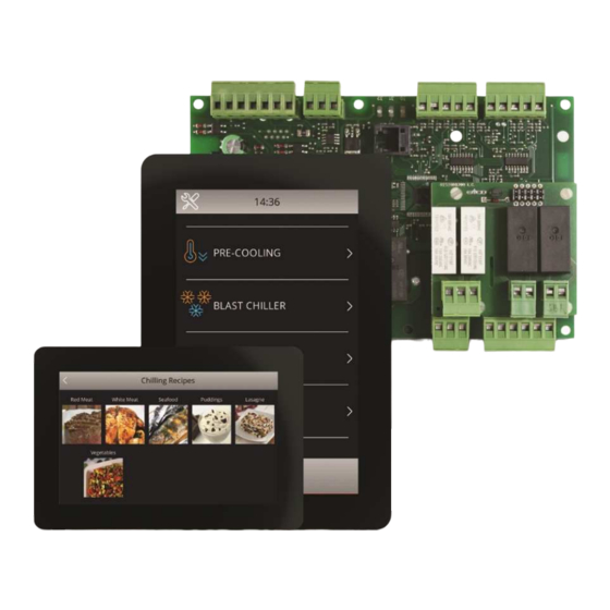
- Page 1 EVCO S.p.A. Vcolor 869/879 | Installer manual ver. 2.2 | Code 144VC869E214 Vcolor 869/879 Controllers for blast chillers with customizable graphical skin ENGLISH INSTALLER MANUAL ver. 2.2 CODE 144VC869E224 page 1 of 94...
- Page 2 EVCO S.p.A. Vcolor 869/879 | Installer manual ver. 2.2 | Code 144VC869E214 Important Read this document carefully before installation and before using the device and take all the prescribed precautions. Keep this document with the device for future consultation. Only use the device in the ways described in this document. Do not use the device as safety device.
-
Page 3: Table Of Contents
EVCO S.p.A. Vcolor 869/879 | Installer manual ver. 2.2 | Code 144VC869E214 Index INTRODUCTION ........................... 6 Introduction ............................6 Main features of the models available ..................... 7 DESCRIPTION ............................ 10 User interface description ........................10 Control module description ........................12 MEASUREMENTS AND INSTALLATION .................... - Page 4 EVCO S.p.A. Vcolor 869/879 | Installer manual ver. 2.2 | Code 144VC869E214 Fish sanitation ........................... 38 Thawing ............................40 Defrosting ............................42 Ice cream hardening........................... 43 Cabinet sterilisation ..........................44 Ionizer .............................. 45 Heating the needle probe ........................46 Drying .............................. 46 Retarding proofing ..........................
- Page 5 EVCO S.p.A. Vcolor 869/879 | Installer manual ver. 2.2 | Code 144VC869E214 LIST OF CONFIGURATION PARAMETERS ....................68 ALARMS ............................80 16.1 Alarms ............................80 16.2 HACCP alarms ..........................85 ACCESSORIES ........................... 86 17.1 EVC20P52N9XXX10 - Multi-functional module ..................86 17.2...
-
Page 6: Introduction
EVCO S.p.A. Vcolor 869/879 | Installer manual ver. 2.2 | Code 144VC869E214 1 INTRODUCTION 1.1 Introduction Vcolor 869/879 manages all the most up-to-date functions of state-of-the-art blast chillers. Besides the traditional blast-chilling blast-freezing cycles, temperature and time controlled with hard/soft function,... -
Page 7: Main Features Of The Models Available
EVCO S.p.A. Vcolor 869/879 | Installer manual ver. 2.2 | Code 144VC869E214 1.2 Main features of the models available La seguente tabella illustra le caratteristiche principali dei modelli disponibili e i codici di acquisto. AVAILABLE MODELS/KITS OPTIONS Vcolor 869M Vcolor 869L... - Page 8 EVCO S.p.A. Vcolor 869/879 | Installer manual ver. 2.2 | Code 144VC869E214 AVAILABLE MODELS/KITS OPTIONS Vcolor 869M Vcolor 869L Speed MAIN FEATURES Expansion module EVlink Wi-Fi (5") (7") regulator EVCMC869P9E EVCLC869P9E EVC20P52N9XXX10 EVDFAN1 EVIF25SWX Digital outputs electro-mechanical relays; A res. @ 250 VAC...
- Page 9 EVCO S.p.A. Vcolor 869/879 | Installer manual ver. 2.2 | Code 144VC869E214 AVAILABLE MODELS/KITS OPTIONS Vcolor 869M Vcolor 869L Speed MAIN FEATURES Expansion module EVlink Wi-Fi (5") (7") regulator EVCMC869P9E EVCLC869P9E EVC20P52N9XXX10 EVDFAN1 EVIF25SWX Other features clock • • •...
-
Page 10: Description
EVCO S.p.A. Vcolor 869/879 | Installer manual ver. 2.2 | Code 144VC869E214 2 DESCRIPTION User interface description The diagram below shows the front view of the user interface in the vertical format PART DESCRIPTION display page 10 of 94... - Page 11 EVCO S.p.A. Vcolor 869/879 | Installer manual ver. 2.2 | Code 144VC869E214 The diagram below shows the intended use of the user interface connectors. PART DESCRIPTION USB port RS-485 MODBUS port dip switch for the termination resistor for the RS-485 MODBUS port...
-
Page 12: Control Module Description
EVCO S.p.A. Vcolor 869/879 | Installer manual ver. 2.2 | Code 144VC869E214 2.2 Control module description The diagram below shows the intended use of the control module connectors. PART DESCRIPTION control module power supply evaporator fan and condenser fan relay... -
Page 13: Measurements And Installation
EVCO S.p.A. Vcolor 869/879 | Installer manual ver. 2.2 | Code 144VC869E214 3 MEASUREMENTS AND INSTALLATION 3.1 Vcolor 869M user interface measurements The picture below shows the measurements of the 5-inch user interface; measurements are expressed in mm (inches). 3.2 Vcolor 869L user interface measurements The picture below shows the measurements of the 7-inch user interface;... -
Page 14: Control Module Measurements
EVCO S.p.A. Vcolor 869/879 | Installer manual ver. 2.2 | Code 144VC869E214 3.3 Control module measurements The picture below shows the measurements of the Vcolor 819 control module; measurements are expressed in mm (inches). Multi-functional module measurements The picture below shows the measurements of the Vcolor 819 multi-functional module; measurements are expressed in mm (inches). -
Page 15: User Interface Installation
EVCO S.p.A. Vcolor 869/879 | Installer manual ver. 2.2 | Code 144VC869E214 User interface installation Mounting of 7"interfaces (Vcolor 869 L): - Flush-fit installation, from behind the panel using threaded studs Mounting of 5"interfaces (Vcolor 869 M): - Flush-fit installation, from behind the panel using threaded studs... -
Page 16: Control And Multi-Functional Module Installation
EVCO S.p.A. Vcolor 869/879 | Installer manual ver. 2.2 | Code 144VC869E214 3.6 Control and multi-functional module installation On a flat surface with spacers. 3.7 Installation precautions Ensure that the working conditions for the device (operating temperature, humidity, etc.) are within the set limits. -
Page 17: Electrical Connection
EVCO S.p.A. Vcolor 869/879 | Installer manual ver. 2.2 | Code 144VC869E214 4 ELECTRICAL CONNECTION 4.1 Electrical connection of Vcolor 869M The picture below shows the electrical connection of the controller with 5-inch display. page 17 of 94... - Page 18 EVCO S.p.A. Vcolor 869/879 | Installer manual ver. 2.2 | Code 144VC869E214 Details of EVlink Wi-Fi electrical connection page 18 of 94...
-
Page 19: Electrical Connection Of Vcolor 869L
EVCO S.p.A. Vcolor 869/879 | Installer manual ver. 2.2 | Code 144VC869E214 4.2 Electrical connection of Vcolor 869L The picture below shows the electrical connection of the controller with 7-inch display. page 19 of 94... -
Page 20: Precautions For Electrical Connection
See section 17 TECHNICAL SPECIFICATIONS. Disconnect the device from the power supply before doing any type of maintenance. Do not use the device as safety device. For repairs and for further information on the device, contact the EVCO sales network. page 20 of 94... -
Page 21: User Interface
EVCO S.p.A. Vcolor 869/879 | Installer manual ver. 2.2 | Code 144VC869E214 5 USER INTERFACE 5.1 Initial information The interface has the following operating modes: “off” (no power to the device); “stand-by” (the device is powered but switched off); “on” (the device is powered, switched on and awaiting start-up of an operating cycle);... - Page 22 EVCO S.p.A. Vcolor 869/879 | Installer manual ver. 2.2 | Code 144VC869E214 Once loading is complete, the device will display the mode it was in before being powered down: On/Stand-by screen, press the central area to move to the Home screen;...
-
Page 23: Switching The Device On And Off
EVCO S.p.A. Vcolor 869/879 | Installer manual ver. 2.2 | Code 144VC869E214 5.3 Switching the device on and off To switch the device on, press the central area in the On/Stand-by screen and the Home screen will open. To switch the device off, press the red area at the bottom of the Home screen. -
Page 24: Operation
EVCO S.p.A. Vcolor 869/879 | Installer manual ver. 2.2 | Code 144VC869E214 6 OPERATION 6.1 Initial information on operating cycles The device is capable of operating in the following modes: temperature controlled blast chilling and conservation hard temperature controlled blast chilling and conservation... -
Page 25: Selecting The Operating Mode
EVCO S.p.A. Vcolor 869/879 | Installer manual ver. 2.2 | Code 144VC869E214 6.3 Selecting the operating mode All the operating functions can be accessed from the Home screen by selecting the specific area. According to the selected machine type (see parameter E13), the Home screen menu will differ as detailed in the following table. -
Page 26: Blast Chilling
EVCO S.p.A. Vcolor 869/879 | Installer manual ver. 2.2 | Code 144VC869E214 7 BLAST CHILLING Press on this area to open the screen shown below. Now one of the areas shown can be selected: blast chilling, blast-freezing, continuous cycle and customized cycle, details below. -
Page 27: Blast Chilling/Blast-Freezing And Conservation
EVCO S.p.A. Vcolor 869/879 | Installer manual ver. 2.2 | Code 144VC869E214 7.1 Blast chilling/blast-freezing and conservation Pressing on one of these areas enables a blast chilling or blast-freezing cycle to be set. The following screen opens and key is activated. If the needle probe is being used and there is no error, the cycle always defaults to temperature control. - Page 28 EVCO S.p.A. Vcolor 869/879 | Installer manual ver. 2.2 | Code 144VC869E214 With temperature controlled cycles, a test is performed to check the correct insertion of the needle probe in the food to be blast-chilled. Should the test not succeed, the cycle is automatically converted to the time mode, the buzzer beeps and the icon symbolizing an alarm underway is displayed.
-
Page 29: Combined Cycle With Slow Cooking
EVCO S.p.A. Vcolor 869/879 | Installer manual ver. 2.2 | Code 144VC869E214 7.1.1 Combined cycle with slow cooking When setting a manual blast chilling/freezing cycle, if available in the machine configuration a slow cooking cycle can be added after a blast chilling/freezing. In the lower part of the screen, two dedicated areas make it possible to add a slow cooking phase or a slow cooking + holding phase. -
Page 30: Continuous Cycle
EVCO S.p.A. Vcolor 869/879 | Installer manual ver. 2.2 | Code 144VC869E214 Once the phase is complete, the controller moves on automatically to the next one. The end of the first two phases is signalled by the buzzer sounding. It is also possible to select the time controlled mode for this cycle, in which case the controller moves on to the next phase when the set time has elapsed. -
Page 31: Multi-Timer Mode
EVCO S.p.A. Vcolor 869/879 | Installer manual ver. 2.2 | Code 144VC869E214 7.3.2 Multi-timer mode The time controlled cycle makes it possible to set up to four timers. The cycle starts up activating only the first timer with its pre-set values. The other timers and their pre-set values can be enabled by pressing the pencil icon and setting a time once the cycle is underway. -
Page 32: Customized Cycle
EVCO S.p.A. Vcolor 869/879 | Installer manual ver. 2.2 | Code 144VC869E214 7.4 Customized cycle The customized mode makes it possible to set up a cycle consisting of a maximum of 4 phases (3 blast chilling and 1 conservation) and these can be temperature or time controlled or a mixture of both. -
Page 33: Setting The Set Points
EVCO S.p.A. Vcolor 869/879 | Installer manual ver. 2.2 | Code 144VC869E214 7.5 Setting the set points 7.5.1 Setting the cabinet temperature set point When selecting a continuous or customized blast chilling or blast-freezing cycle, the pre-set cabinet temperature, product temperature, time and fan speed values when the parameters were set are loaded. -
Page 34: Running The Cycle
EVCO S.p.A. Vcolor 869/879 | Installer manual ver. 2.2 | Code 144VC869E214 Running the cycle Pressing the key starts up the cycle as it has been set. If it is a temperature controlled cycle, the blast chilling/blast-freezing phases terminate when the needle probe, or probes, reach the set temperature. If it is a time controlled cycle, the blast chilling/blast-freezing phases terminate when the set time period, or periods, have elapsed. -
Page 35: Recording Historical Data
EVCO S.p.A. Vcolor 869/879 | Installer manual ver. 2.2 | Code 144VC869E214 The sensor showing the highest temperature is then used as the reference point for the end of the temperature controlled cycles. Any sensors for which the test is not completed with a successful outcome are not subsequently used. - Page 36 EVCO S.p.A. Vcolor 869/879 | Installer manual ver. 2.2 | Code 144VC869E214 In time controlled cycles, , pressing the key will bring up the screen granting access to the following functions. record the cycle just performed in the memory. page 36 of 94...
-
Page 37: Special Cycles
EVCO S.p.A. Vcolor 869/879 | Installer manual ver. 2.2 | Code 144VC869E214 SPECIAL CYCLES Press this area on the Home page to open the screen shown below. This screen grants access to further functions, some always present, others that can be activated by setting the parameter. -
Page 38: Fish Sanitation
EVCO S.p.A. Vcolor 869/879 | Installer manual ver. 2.2 | Code 144VC869E214 Pressing this area enables selection of a drying cycle (a function activated with the door closed); see section 8.7. Pressing this area enables selection of a retarding proofing cycle (a function activated by parameter);... - Page 39 EVCO S.p.A. Vcolor 869/879 | Installer manual ver. 2.2 | Code 144VC869E214 The sanitation cycle starts with the blast chilling phase. When the temperature recorded by the needle probe reaches the temperature to end blast chilling, the device will move on automatically to holding.
-
Page 40: Thawing
EVCO S.p.A. Vcolor 869/879 | Installer manual ver. 2.2 | Code 144VC869E214 8.2 Thawing Pressing this area enables selection of a thawing cycle, managed according to the load of product to be thawed, in compliance with the maximum quantity stated by the manufacturer. - Page 41 EVCO S.p.A. Vcolor 869/879 | Installer manual ver. 2.2 | Code 144VC869E214 set 1 = initial set point set 2 = final set point Five parameters are used to manage the ventilation, one for each phase, setting the fan speed independently of the load.
-
Page 42: Defrosting
EVCO S.p.A. Vcolor 869/879 | Installer manual ver. 2.2 | Code 144VC869E214 8.3 Defrosting Pressing this area enables selection of a manual defrosting cycle, which is started up by pressing area . When the cycle starts up the following page is displayed. -
Page 43: Ice Cream Hardening
EVCO S.p.A. Vcolor 869/879 | Installer manual ver. 2.2 | Code 144VC869E214 Defrosting finishes when the evaporator temperature is above the value of parameter d2 or if the temperature has not been reached within the required time set by parameter d3. -
Page 44: Cabinet Sterilisation
EVCO S.p.A. Vcolor 869/879 | Installer manual ver. 2.2 | Code 144VC869E214 8.5 Cabinet sterilisation Pressing this area enables selection of a sterilisation cycle. The cabinet door must be closed to start up a sterilisation cycle. Pressing the key starts up the sterilisation cycle. -
Page 45: Ionizer
EVCO S.p.A. Vcolor 869/879 | Installer manual ver. 2.2 | Code 144VC869E214 8.6 Ionizer The ionizer is an alternative function to the UV lamp function, inherent in the sterilization cycle. Based on parameter E17, the type of sterilization present in the device will be defined and consequently the relative icon will be displayed. -
Page 46: Heating The Needle Probe
EVCO S.p.A. Vcolor 869/879 | Installer manual ver. 2.2 | Code 144VC869E214 During storage, whether it has been activated automatically by parameter E18 or manually by key, the ionizer remains on for the time defined by the new parameter E19. -
Page 47: Retarding Proofing
EVCO S.p.A. Vcolor 869/879 | Installer manual ver. 2.2 | Code 144VC869E214 This is a cycle of forced-air ventilation that can be activated with the door closed and for a duration set by parameter u13. If the door is opened during drying this does not affect the cycle. - Page 48 EVCO S.p.A. Vcolor 869/879 | Installer manual ver. 2.2 | Code 144VC869E214 A retarding proofing cycle consists of 5 phases with different temperatures, relative humidity, fan speeds and durations, one following on from the other, as in the sequence described below.
-
Page 49: Setting Up A Retarding Proofing Cycle
EVCO S.p.A. Vcolor 869/879 | Installer manual ver. 2.2 | Code 144VC869E214 8.9.2 Setting up a retarding proofing cycle 8.9.2.1 Starting and stopping a cycle Press the key to access to the following screen displaying all the phases making up a RETARDING-PROOFING cycle:... - Page 50 EVCO S.p.A. Vcolor 869/879 | Installer manual ver. 2.2 | Code 144VC869E214 using the special menus and once the key has been pressed, the proofing cycle starts up. It is not possible to modify the set points while the cycle is in progress. If a phase is set at 0, it will not be run. In the blast chilling phase the cabinet humidity control can be omitted using parameter rU4, but this must be set in the other phases.
-
Page 51: Slow Cooking
EVCO S.p.A. Vcolor 869/879 | Installer manual ver. 2.2 | Code 144VC869E214 Alternatively, the cycle end date can be postponed using the quick key. 8.10 Slow cooking Pressing this area enables selection of a slow cooking cycle, which can consist of two phases. This function can only be enabled if an expansion has been set (see parameter E12). - Page 52 EVCO S.p.A. Vcolor 869/879 | Installer manual ver. 2.2 | Code 144VC869E214 fan speed Two areas at the bottom of the screen make it possible to add a subsequent blast chilling/blast-freezing phase and a product holding/conservation phase For blast chilling or blast-freezing, the pre-settings are those for the cycle, whereas the following parameters are used...
-
Page 53: Conservation
EVCO S.p.A. Vcolor 869/879 | Installer manual ver. 2.2 | Code 144VC869E214 8.11 Conservation Press this area to select a conservation in cooling, heating or neutral zone mode. The presettings of the cooling cycle are those of the blast-chilling, while the presettings of heating and neutral zone cycles are those of slow cooking. -
Page 54: Recipe Book
Confirm and wait until the device re-starts automatically. To reset to factory defaults, the procedure to follow is the same as indicated above. For more details on the "OEM" recipe saving procedure, please contact the EVCO sales network. page 54 of 94... -
Page 55: My Cookbook" Recipe Book
EVCO S.p.A. Vcolor 869/879 | Installer manual ver. 2.2 | Code 144VC869E214 9.2 "MY COOKBOOK" recipe book It is an area dedicated to the final customer. It is possible to save up to 40 recipes using the Western alphabet and without translation. - Page 56 EVCO S.p.A. Vcolor 869/879 | Installer manual ver. 2.2 | Code 144VC869E214 Scroll the page and select the desired position where to save a new recipe or overwrite an existing one; Press to confirm : the alphabetic keyboard is now accessible (press to exit the procedure without saving);...
-
Page 57: Starting "My Cookbook" Recipes
EVCO S.p.A. Vcolor 869/879 | Installer manual ver. 2.2 | Code 144VC869E214 9.2.2 Starting “MY COOKBOOK” recipes To start a recipe, operate as follows: Make sure the device is on and no procedure is underway;. Touch the Enter the menu and select the desired recipe... -
Page 58: Pre-Cooling
EVCO S.p.A. Vcolor 869/879 | Installer manual ver. 2.2 | Code 144VC869E214 PRE-COOLING Pressing this area on the Home page enables selection of a pre-cooling cycle. This cycle is similar to a normal blast chilling cycle and it may precede all operating cycles. -
Page 59: Adjustments
EVCO S.p.A. Vcolor 869/879 | Installer manual ver. 2.2 | Code 144VC869E214 ADJUSTMENTS 11.1 Door frame heating output This function is only available if one of the relays is configured as door frame heating. This function is activated automatically when the board is in “on” or “run” mode and the cabinet temperature falls below the value set by parameter u5 minus the fixed hysteresis of 2°C (4°F). -
Page 60: Pump Down Solenoid Valve Management
EVCO S.p.A. Vcolor 869/879 | Installer manual ver. 2.2 | Code 144VC869E214 When regulating with 2 compressors, the differential set by parameter r0 will be halved: that means that the differential for each compressor is “r0/2”. When regulation requires the activation of both compressors, the second compressor will be activated with a delay set by parameter C10. - Page 61 EVCO S.p.A. Vcolor 869/879 | Installer manual ver. 2.2 | Code 144VC869E214 The evaporator fan management differs according to the cycle in use, as specified below. The way the evaporator fan is managed changes depending on the presence of the evaporator probe, which is enabled setting parameter P4 to 1.
-
Page 62: Condenser Fan Management
EVCO S.p.A. Vcolor 869/879 | Installer manual ver. 2.2 | Code 144VC869E214 11.6 Condenser fan management This function is only available if one of the relays is configured as condenser fan. The fan only turn on during one cycle. The management mode of condenser fans varies according to whether the condenser probe is present, which can be enabled by setting parameter P5 to 1. -
Page 63: Thawing Heater Management
EVCO S.p.A. Vcolor 869/879 | Installer manual ver. 2.2 | Code 144VC869E214 During defrosting outputs are managed according to the type of defrost set by parameter d1. The defrost output will be activated regardless of the value of parameter d1 for the entire duration of the defrost. -
Page 64: Settings
EVCO S.p.A. Vcolor 869/879 | Installer manual ver. 2.2 | Code 144VC869E214 SETTINGS user recipes The SETTINGS are accessed by pressing area 12.4 Select language the Home page. The page displays the following menu: Press this area to select the desired language among time and date;... -
Page 65: Using The Usb Port
EVCO S.p.A. Vcolor 869/879 | Installer manual ver. 2.2 | Code 144VC869E214 USING THE USB PORT 13.1 Initial information The USB port makes possible the following operations. upload and download settings of “MY COOKBOOK” recipes and of “Special cycles” working cycles (hereinafter referred to as “programs”);... -
Page 66: Downloading Configuration Param. Settings (Controller -> Usb)
EVCO S.p.A. Vcolor 869/879 | Installer manual ver. 2.2 | Code 144VC869E214 13.1.4 Downloading configuration param. settings (controller -> USB) To download the settings of the configuration parameter, operate as follows: Make sure the device is in stand-by and no procedure is underway;... -
Page 67: Epoca Cloud Platform
EVCO S.p.A. Vcolor 869/879 | Installer manual ver. 2.2 | Code 144VC869E214 EPOCA CLOUD PLATFORM EPoCA is a remote monitoring system based on a cloud platform. All that is needed is a simple onsite Wi-Fi internet connection to enable the controller, using EVlink Wi-Fi module, to connect to the cloud system, making it possible to remotely manage equipment from a PC, tablet or smartphone. -
Page 68: List Of Configuration Parameters
EVCO S.p.A. Vcolor 869/879 | Installer manual ver. 2.2 | Code 144VC869E214 LIST OF CONFIGURATION PARAMETERS The following table gives the meaning of the configuration parameters. N.B. Because some functions are managed according to the value set for some parameters, ensure these are set correctly and consistently. - Page 69 EVCO S.p.A. Vcolor 869/879 | Installer manual ver. 2.2 | Code 144VC869E214 PAR. DEFAULT MIN. MAX. U.M. MAIN REGULATOR Cabinet set point differential in blast chilling, blast-freezing, °C/°F sanitation, ice cream hardening and customized cycles. Duration of time controlled blast chilling...
- Page 70 EVCO S.p.A. Vcolor 869/879 | Installer manual ver. 2.2 | Code 144VC869E214 Product temperature set point for the first phase of sanitation and °C/°F cabinet temperature set point for the second phase of sanitation. Duration of second sanitation phase. °C/°F Cabinet temperature set point for the third phase of sanitation.
- Page 71 EVCO S.p.A. Vcolor 869/879 | Installer manual ver. 2.2 | Code 144VC869E214 °C/°F Cabinet temperature set point for re-awakening phase. °C/°F Cabinet temperature set point for proofing phase. °C/°F Cabinet temperature set point for holding phase. °C/°F Neutral zone relative threshold (heating) for all proofing phases.
- Page 72 EVCO S.p.A. Vcolor 869/879 | Installer manual ver. 2.2 | Code 144VC869E214 Pre-set % humidifying during proofing Pre-set % humidifying during holding rU10 Pre-set % humidifying during slow cooking. rU11 Pre-set % humidifying during holding after slow cooking. PAR. DEFAULT MIN.
- Page 73 EVCO S.p.A. Vcolor 869/879 | Installer manual ver. 2.2 | Code 144VC869E214 or provided the door switch input is on and that parameter i0 is set to a value other than 0). Evaporator temperature to end defrosting. See also parameter °C/°F...
- Page 74 EVCO S.p.A. Vcolor 869/879 | Installer manual ver. 2.2 | Code 144VC869E214 Power failure duration sufficient for the power failure alarm to be saved (“POWER FAILURE” code) when this is restored = the alarm will not be signalled °C/°F Parameter A1 and A4 differential Duration of buzzer activation on completion of blast chilling and blast-freezing.
- Page 75 EVCO S.p.A. Vcolor 869/879 | Installer manual ver. 2.2 | Code 144VC869E214 - - - - Fan speed in first sanitation phase (blast chilling). - - - - Fan speed in second sanitation phase (holding). - - - - Fan speed in third sanitation phase (conservation).
- Page 76 EVCO S.p.A. Vcolor 869/879 | Installer manual ver. 2.2 | Code 144VC869E214 PAR. DEFAULT MIN. MAX. U.M. DIGITAL INPUTS Effect caused by the door opening, or when the door switch input is activated. = no effect and no signal = the compressor, evaporator fan, thawing heater, heater...
- Page 77 EVCO S.p.A. Vcolor 869/879 | Installer manual ver. 2.2 | Code 144VC869E214 Function managed by output K1 Unused Compressor 1 Compressor 2 Defrost Evaporator fan Condenser fan Door heater u01c - - - - Thawing heater Alarm Pump down valve 10.
- Page 78 EVCO S.p.A. Vcolor 869/879 | Installer manual ver. 2.2 | Code 144VC869E214 Temperature to end needle probe heating. See also parameter °C/°F Maximum duration of needle probe heating. See also parameter u7 0 = needle probe heating is disabled. - - - -...
- Page 79 EVCO S.p.A. Vcolor 869/879 | Installer manual ver. 2.2 | Code 144VC869E214 Display EVCO splash screen when power is restored - - - - = no = yes Humidifying/steam generator heater management mode = output is always active in the cycles for which humidifying...
-
Page 80: Alarms
EVCO S.p.A. Vcolor 869/879 | Installer manual ver. 2.2 | Code 144VC869E214 ALARMS 16.1 Alarms The table below lists the various alarms. Code Meaning Clock error. To correct Re-set the date and time. Main consequences The device will not memorise the date and time an HACCP alarm happened. - Page 81 EVCO S.p.A. Vcolor 869/879 | Installer manual ver. 2.2 | Code 144VC869E214 Condenser probe error. To correct The same as for the cabinet probe error but with reference to the condenser probe. Main consequences CONDENSER PROBE The condenser fan will operate in parallel with the compressor.
- Page 82 EVCO S.p.A. Vcolor 869/879 | Installer manual ver. 2.2 | Code 144VC869E214 High pressure alarm. To correct Check the state of the high pressure input. HIGH PRESSURE Check the value of parameter i6. SWITCH Main consequences If the cycle underway requires use of the compressor, the cycle will be interrupted.
- Page 83 EVCO S.p.A. Vcolor 869/879 | Installer manual ver. 2.2 | Code 144VC869E214 User interface-control module communication error. To correct BOARD COMMUNICATIO Check the user interface-control module connection. Main consequences Any cycle underway will be terminated and it will not be possible to start one up.
- Page 84 EVCO S.p.A. Vcolor 869/879 | Installer manual ver. 2.2 | Code 144VC869E214 Compressor locked alarm. To correct Check the condenser temperature Check the value of parameter C7 COMPRESSOR Disconnect the device from the power supply and clean the condenser. LOCKED Main consequences If the error happens during “stand-by”, it will not be possible to select or start up an...
-
Page 85: Haccp Alarms
EVCO S.p.A. Vcolor 869/879 | Installer manual ver. 2.2 | Code 144VC869E214 16.2 HACCP alarms To access the HACCP alarm area, press area in the Home screen. The screen below will be displayed. The following HACCP alarms are listed. Blast chilling/blast-freezing cycle duration... -
Page 86: Accessories
EVCO S.p.A. Vcolor 869/879 | Installer manual ver. 2.2 | Code 144VC869E214 ACCESSORIES 17.1 EVC20P52N9XXX10 - Multi-functional module The module makes it possible to add to the controller’s potential functions, enabling special cycles to be managed with control of heating and steam generation and injection. -
Page 87: 0812000002 - Usb Plug For Panel Installation
EVCO S.p.A. Vcolor 869/879 | Installer manual ver. 2.2 | Code 144VC869E214 17.4 0812000002 - USB plug for panel installation This plug makes the controller’s USB port more accessible. To connect the plug to the USB port, connecting cable 0810500018 or 0810500020 must be used (to be ordered separately). -
Page 88: Evusb4096M - 4Gb Usb Flash Drive
EVCO S.p.A. Vcolor 869/879 | Installer manual ver. 2.2 | Code 144VC869E214 17.7 EVUSB4096M - 4GB USB flash drive This flash drive makes it possible to upload and download the controller configuration and the customized cycles saved by the user. HACCP data can also be exported in CSV format. -
Page 89: Technical Specifications
EVCO S.p.A. Vcolor 869/879 | Installer manual ver. 2.2 | Code 144VC869E214 TECHNICAL SPECIFICATIONS 18.1 Technical specifications Purpose of the control device Function controller. Construction of the control device Built-in electronic device. user interface control module Container Open frame board behind glass. - Page 90 EVCO S.p.A. Vcolor 869/879 | Installer manual ver. 2.2 | Code 144VC869E214 RoHS 2011/65/EC Environmental standards WEEE 2012/19/EU REACH (EC) Regulation no. 1907/2006. EN 60730-1 EMC standards IEC 60730-1. user interface control module Vcolor 869M (5"): powered by the control module.
- Page 91 EVCO S.p.A. Vcolor 869/879 | Installer manual ver. 2.2 | Code 144VC869E214 9, electro-mechanical relays The maximum permitted current on loads 3 and 4 is 10 A, on load K1 is 20 A (see the electrical circuit diagram). The relays do not manage LED and fluorescent lamps Compressor relay: 30 A SPST res.
- Page 92 EVCO S.p.A. Vcolor 869/879 | Installer manual ver. 2.2 | Code 144VC869E214 page 92 of 94...
- Page 93 This document is the exclusive property of EVCO and any reproduction or disclosure is absolutely prohibited unless expressly authorised by EVCO. EVCO accepts no liability for the features and technical data described in this document and for any errors it may contain or that can arise from its use.
- Page 94 EVCO S.p.A. Vcolor 869/879 | Installer manual ver. 2.2 | Code 144VC869E214 EVCO S.p.A. Via Feltre 81, 32036 Sedico Belluno ITALIA Tel. 0437 / 8422 Fax 0437 / 83648 info@evco.it www.evco.it page 94 of 94...
Need help?
Do you have a question about the Vcolor 869 and is the answer not in the manual?
Questions and answers