
Subscribe to Our Youtube Channel
Related Manuals for Evco Vcolor 279


Summary of Contents for Evco Vcolor 279
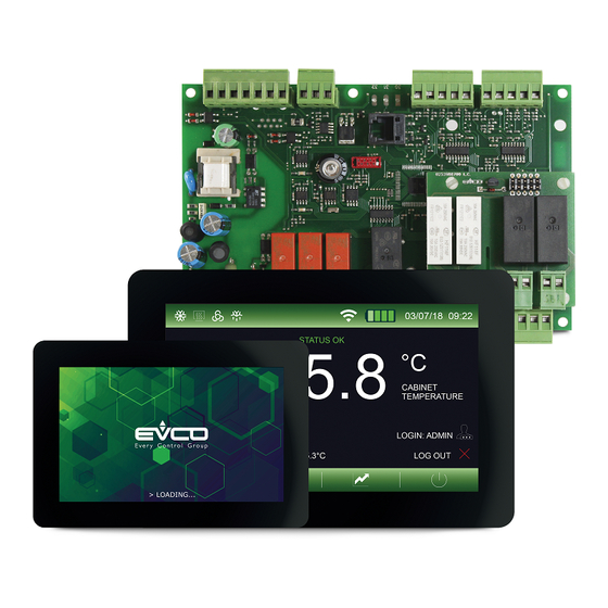
- Page 1 Applications Laboratory cabinets Vcolor 279 Application Manual Controller for laboratory cabinets 144VC279I104...
- Page 2 Vcolor 279 - Application manual IMPORTANT Read this document carefully before installation and take all precautions before using the device. Only use the device in the ways described in this document. CONSIDER THE ENVIRONMENT Keep this document with the device for future reference.
-
Page 3: Table Of Contents
|Control module |Backup module |I/O expansion | Electrical connections |Vcolor 279 M user interface |Description of connectors |Electrical connection |User interface - Vcolor 279 L |Description of connectors |Electrical connection |Control module |Description of connectors |Electrical connection |EVlink Wi-Fi module... - Page 4 Vcolor 279 - Application manual |I/O expansion |Description of connectors |Electrical connection |Vcolor 279 M |Electrical connection |Vcolor 279 L |Electrical connection | Description of graphic interface |Regulator status icons |Function keys |Main menu icons |Historical data icons |Service icons...
- Page 5 Vcolor 279 - Application manual | USB port management | EPoCA cloud platform | Alarms |Table of alarms | List of parameters | Accessories |Connecting cables |USB flash drive |RS-485/USB serial interface |Safety transformer |USB plug for panel installation |4 relay I/O expansion...
-
Page 6: Introduction
Vcolor 279 - Application manual Introduction Vcolor 279 is a controller for refrigerated units and has 9 sealed relays (which can be expanded to 13) to meet the most sophisticated management needs in sectors such as laboratory refrigeration. Regulation and reading accuracy is guaranteed by 3-point probe calibration and access to controller functions is hierarchically subject to user identification to increase the level of protection. -
Page 7: Vcolor 279 Solution
Vcolor 279 - Application manual Vcolor 279 solution The Vcolor 279 is available in the split version with a control module combined with a 5-inch (Vcolor 279 M) or 7-inch (Vcolor 279 L) user interface. This basic configuration can be connected to a series of optional modules illustrated below, increasing its functions and making Vcolor 279 a complete control solution that can be customised to everyone’s needs. -
Page 8: Main Features And Purchasing Codes Of The Controller
Vcolor 279 - Application manual Main features and purchasing codes of the controller Vcolor 279 M&L Vcolor 279 EVCMC279Z9E EVCLC279Z9E Interface format Capacitive TFT touch-screen graphic display in glass 5 inch (M) 7 inch (L) Power supply From the control... -
Page 9: Main Features And Purchasing Codes Of The Optional Modules
Vcolor 279 - Application manual Main features and purchasing codes of the optional modules Backup module EVPS9B Power supply 115... 230 VAC • Analogue inputs (PT1000 2 wires) • Probe 4 configurable (default product probe) • Digital outputs (electro-mechanical relays, A res. at 250 VAC) -
Page 10: Measurements
Vcolor 279 - Application manual Measurements Vcolor 279 M user interface 5” 1.9 mm R 10 mm 108 mm 35 mm 142 mm 78 mm 78 mm 166 mm Vcolor 279 L user interface 7” 3 mm R 8 mm 152.8 mm... -
Page 11: Control Module
Vcolor 279 - Application manual Control module 46 mm 5 mm 44 mm 68 mm Ø 4 mm 69 mm 166 mm Backup module 60 mm 71 mm I/O expansion 004_Vcolor279_M&L_Modulo_001_0.1_AZ 91 mm 24 mm 99 mm 144VC279I104 | 11... -
Page 12: Installation
Vcolor 279 - Application manual Installation INSTALLATION PRECAUTIONS – Ensure that the working conditions are within the limits stated in the “Technical specifications” section. – Do not install the device close to heat sources, equipment with a strong magnetic field, in places subject to direct sunlight, rain, damp, excessive dust, mechanical vibrations or shocks. -
Page 13: Vcolor 279 M/L User Interface
Vcolor 279 - Application manual Vcolor 279 M/L user interface Device The user interface is installed from behind using threaded Threaded stud studs. In this way the interface can be placed flush with the panel, thus making it fit perfectly with the design of the unit. -
Page 14: Backup Module
Vcolor 279 - Application manual Backup module The backup module is installed on a DIN rail. To install the device, proceed as shown in figures 1 and 2. To remove the device, first remove any plug-in screw terminal blocks at the bottom then proceed as shown in figures 3 and 4. -
Page 15: Electrical Connections
Disconnect the power supply before carrying out any type of maintenance – Do not use the device as a safety device – For repairs and further information, contact the EVCO sales network; returned goods without the data label will not be accepted 144VC279I104 | 15... -
Page 16: Vcolor 279 M User Interface
Vcolor 279 - Application manual Vcolor 279 M user interface Description of connectors Connector 1 - USB Conn. 3 Conn. 2 Conn. 1 Number Description 36 35 34 33 30 31 32 USB communications port Connector 2 - RS-485 MODBUS port... -
Page 17: User Interface - Vcolor 279 L
Vcolor 279 - Application manual User interface - Vcolor 279 L Description of connectors Connector 1 - USB Conn. 1 Conn. 2 Conn. 3 Number Description 30 31 32 33 34 35 36 USB communications port Connector 2 - RS-485 MODBUS port... -
Page 18: Control Module
Vcolor 279 - Application manual Control module Description of connectors Connector 1 - Power supply 42 41 40 39 38 37 36 35 34 33 32 31 30 29 28 27 26 24 23 22 21 Number Description Conn. 10 Conn. -
Page 19: Electrical Connection
Vcolor 279 - Application manual Electrical connection Unused 42 41 40 39 38 37 36 35 34 33 32 31 30 29 28 27 26 24 23 22 21 Backup battery test Control module 1 2 3 4 5 6... -
Page 20: Backup Module
Vcolor 279 - Application manual Backup module Description of connectors Connector 1 - Probe 4 Conn. 1 Conn. 2 Conn. 3 Number Description 11 12 14 15 16 17 18 19 Probe 4 common contact Probe 4 Connector 2 - Device network... -
Page 21: I/O Expansion
Vcolor 279 - Application manual I/O expansion Description of connectors Connector 1 - Device network Conn. 1 Number Description 27 26 25 24 23 22 21 20 19 18 17 16 Unused Signal B (-) RS-485 MODBUS port Conn. 2... -
Page 22: Vcolor 279 M
Vcolor 279 - Application manual Vcolor 279 M Electrical connection 144VC279I104 | 22... -
Page 23: Vcolor 279 L
Vcolor 279 - Application manual Vcolor 279 L Electrical connection 144VC279I104 | 23... -
Page 24: Description Of Graphic Interface
Vcolor 279 - Application manual Description of graphic interface Regulator status icons 03/07/18 09:22 During machine operation, the status of the main regulators is displayed through the icons at the top of the screen. Compressor 1 active Compressor 2 active... -
Page 25: Main Menu Icons
Vcolor 279 - Application manual Main menu icons The icons in the main menu are used to select the machine’s Adjust working setpoint functions. They are displayed in the centre of the screen by pressing the “MAIN MENU” key. Select manual defrost... -
Page 26: Service Icons
Vcolor 279 - Application manual Service icons Set date and time The icons in the service menu are used to set basic machine functions and are displayed in the “SERVICE” menu Input and output status List of alarms Set unit name... -
Page 27: Navigation
When the device is powered up for the first time or after a power failure, a splash screen will appear for a couple of seconds: if E9=0, the EVCO logo will appear; if E9=1, a neutral loading screen or the personalised graphic skin (if uploaded) will appear. -
Page 28: Main Menu
Vcolor 279 - Application manual Main menu All the functions in the main menu are always available if parameter “E17=0”, whereas if E17 = 1 they are only available to the “Admin” user or other users enabled to carry out the specific function. To enable users, consult the section “USER ID MANAGEMENT”. - Page 29 Vcolor 279 - Application manual DOOR LOCK The door lock can be unlocked/locked from the “DOOR LOCK” menu. HISTORICAL DATA Recorded data, events and machine alarms can be consulted from the “HISTORICAL DATA” menu: – “ALARM HISTORY” – “DEFROST HISTORY”...
- Page 30 Vcolor 279 - Application manual COUNTER HISTORY A report of the machine operating times can be visualised from the “COUNTER HISTORY” menu. The following information is given: – total hours machine was switched on (if the value is above 23:59 minutes, the number of days is displayed) –...
- Page 31 Vcolor 279 - Application manual SETUP HISTORICAL DATA Information to store in the history can be selected from the “SETUP HISTORICAL DATA” menu. The following information can be selected: page 1 – Temperature detected by the cabinet probe – Temperature detected by the product probe –...
- Page 32 Vcolor 279 - Application manual USER ID MANAGEMENT Users need to access the application with a password. When the device is switched on, a stand-by screen will appear with an area at the bottom right if the enable users parameter “E17” is set to 1. To access the application, press the green “Login”...
- Page 33 Vcolor 279 - Application manual LANGUAGES The language can be set from the “LANGUAGE” menu The languages available are: – English – Italian – Spanish – German – French SERVICE The following information can be accessed from the “SERVICE” menu –...
- Page 34 Vcolor 279 - Application manual WELCOME PAGE By activating the “WELCOME PAGE” icon when the machine is switched on, it is possible to visualise a series of screens which enable the user to quickly set the controller preferences using a wizard (see the section “Preferences settings screen”).
- Page 35 Vcolor 279 - Application manual SETTINGS The page to configure parameters and the page to restore EVCO default values can be accessed from the “SETTINGS” menu. SETTING PARAMETERS Press “SET PARAMETERS” IMPOSTAZIONE PARAMETRI to configure the parameters, after entering the password set by parameter “PAS”.
-
Page 36: Graph Screen
Vcolor 279 - Application manual Graph screen Pressing the “GRAPH” key gives access to the screen where the temperature graph is displayed in real time. Through parameter rE0, which can be set in 5-minute steps, it is possible to define the time scale of the graph as shown in the example below. -
Page 37: Configuring Inputs/Outputs
Vcolor 279 - Application manual Configuring inputs/outputs Configuring temperature probes The controller can manage four PT1000 temperature probes, three of which are on the control module and one on the backup module. The name of the first probe on the control module is set by parameter “Pr1”; similarly, the names of the other probes are set by parameters “Pr2”, “Pr3”... -
Page 38: Configuring Digital Inputs
Vcolor 279 - Application manual Configuring digital inputs The controller can manage four digital inputs: – 1 dedicated input which detects door status – 3 multi-purpose (MP) inputs which can be configured to detect different things The function associated with the MP inputs is set by parameters “i5 - i8 - i11” based on the following settings: –... -
Page 39: Regulations
Vcolor 279 - Application manual Regulations Compressor management The compressor is activated when the temperature of the regulation probe is higher than the regulation setpoint value and is deactivated when the temperature of the regulation probe goes below the regulation setpoint value. -
Page 40: Condenser Fan Management
Vcolor 279 - Application manual Whenever fan management depends on the evaporator probe, the controller uses the replacement regulation probe if the probe is in alarm mode or not enabled. The evaporator fans are switched off in the following conditions: –... -
Page 41: On/Stand-By Output Management
Vcolor 279 - Application manual ON/stand-by output management The ON/stand-by output is activated if the board is ON and is deactivated if the board is OFF. Light management The light comes on when the door is opened if “i0” > 2, it goes off when the door is closed. -
Page 42: Operating Mode: "Defrost
Vcolor 279 - Application manual Operating mode: “defrost” Defrost can be activated manually from the user interface (through the dedicated icon in the “main menu”) or automatically in the following cases: – “d4 = 1” At switch-on after a delay of “d5” minutes –... - Page 43 Vcolor 279 - Application manual USB port management The following operations can be carried out through the USB port: – Download the parameters saved in the controller to a USB flash drive – Upload the parameters in the USB flash drive to the controller –...
- Page 44 Vcolor 279 - Application manual Alarms When there is an alarm, a buzzer will sound and the icon will appear. ALL. SONDA CELLA The kind of alarm is indicated by a message at the top of the screen, for example To silence the buzzer, press the icon “BUZZER”...
- Page 45 Vcolor 279 - Application manual Alarm label Description PRE-ALARM LOW T. CABINET High cabinet temperature pre-alarm To correct: – Check the cabinet temperature – Check the value of parameter “A12” or “A11” depending on the configuration as absolute or relative values set with parameter “A5”...
- Page 46 Vcolor 279 - Application manual Alarm label Description COMPRESSOR 1 HP HP pressure switch alarm compressor 1 To correct: – Check the condition of the multi-purpose input (MP) associated with this function Main results: – Compressor 1 off COMPRESSOR 2 HP...
- Page 47 Vcolor 279 - Application manual Alarm label Description CO2 BACKUP Alarm occurring when backup probe temperature> u9+u10 (if u14c = 2) Main results: – The backup module relay will be activated THERMOSTAT AL Alarm occurring when backup probe temperature> u9+u10 (if u14c = 3) Main results: –...
- Page 48 Vcolor 279 - Application manual List of parameters Label Description Default Setpoint -99.9 99.9 -40.0 °C/F Probe 1 offset -25.0 25.0 °C/F Probe 2 offset -25.0 25.0 °C/F Probe 3 offset -25.0 25.0 °C/F Probe 4 offset -25.0 25.0 °C/F Enable decimal point °C...
- Page 49 Vcolor 279 - Application manual Label Description Default High condensation signal threshold 164.0 80.0 °C/F High condensation alarm threshold (once “C8” has elapsed) 164.0 90.0 °C/F Delay of compressor locked alarm (due to threshold “C7” exceeded) UNUSED Operating time of compressor due to maintenance warning...
- Page 50 Vcolor 279 - Application manual Label Description Default Absolute threshold for low cabinet temp. alarm -99.0 99.9 -50.0 °C/F Absolute threshold for high cabinet temp. alarm -99.0 99.9 25.0 °C/F Threshold relative to setpoint for low cabinet temperature alarm -50.0 -3.0...
- Page 51 Vcolor 279 - Application manual Label Description Default Evaporator setpoint differential 15.0 °C/F Evaporator fans OFF delay from compressor OFF Condenser fan mode 0 thermoregulated 1 thermoregulated if compressor OFF 2 thermoregulated if compressor OFF, OFF in defrost Condenser fans ON threshold 99.0...
- Page 52 Vcolor 279 - Application manual Label Description Default Compressor protection effect 0 none 1 compressors OFF u01c Output K1 configuration 0 compressor 1 1 compressor 2 2 evaporator fans 3 condenser 1 fans 4 defrost 5 light 6 heater 7 alarm...
- Page 53 Vcolor 279 - Application manual Label Description Default Door heaters threshold -99.0 99.0 -1.0 °C/F Door lock activation 0 contact closed 1 contact open Enable alarm buzzer 0 no 1 yes Backup module alarm delay 1440 Backup module alarm threshold -99.0...
- Page 54 Vcolor 279 - Application manual Label Description Default Secondary value on display 0 probe 1 1 probe 2 2 probe 3 3 probe 4 Enable power meter 0 no 1 yes Maximum voltage threshold Minimum voltage threshold Maximum current threshold Minimum current threshold N.B.
- Page 55 Allows configuration upload and download. 4GB of memory. RS-485/USB serial interface EVIF20SUXI Using the RS-485 communications port, the controller can be connected to the Parameters Manager set-up software. Safety transformer ECTSFD004 The transformer can power the Vcolor 279 L user interface. 144VC279I104 | 55...
- Page 56 Vcolor 279 - Application manual USB plug for panel installation 0812000002 This plug grants access to the controller’s USB communications port. To connect the port to the plug, connecting cable 0810500018 or 0810500020 must be used (to be ordered separately).
- Page 57 Vcolor 279 - Application manual Technical specifications User interface - Control module Type Description Purpose of the control device Function controller Construction of the control device Built-in electronic device Housing User interface Open frame board behind glass Control module Open frame board...
- Page 58 Vcolor 279 - Application manual Type Description Clock Built-in With secondary lithium battery Clock drift ≤ 60 s/month at 25 °C Clock battery autonomy in the > 6 months at 25 °C absence of a power supply Clock battery charging time...
- Page 59 Vcolor 279 - Application manual 144VC279I104 | 59...
- Page 60 EVCO. The customer (manufacturer, installer or end user) assumes all responsibility for the configuration of the device. EVCO accepts no liability for any possible errors in this document and reserves the right to make any changes at any time without prejudice to the essential functional and safety features of the equipment.
Need help?
Do you have a question about the Vcolor 279 and is the answer not in the manual?
Questions and answers