
Subscribe to Our Youtube Channel
Related Manuals for Evco Vcolor 388


Summary of Contents for Evco Vcolor 388
- Page 1 EVCO S.p.A. Vcolor 388 | Installer manual ver. 1.0 | Code 144VC388E104 Vcolor 388 Controllers for steam tube deck ovens ENGLISH INSTALLER MANUAL ver. 1.0 CODE 144VC388E104 Page 1 of 44...
- Page 2 EVCO S.p.A. Vcolor 388 | Installer manual ver. 1.0 | Code 144VC388E104 Important Read this document carefully before installation and before using the device and take all the prescribed precautions. Keep this document with the device for future consultation. Only use the device in the ways described in this document. Do not use the device as a safety device.
-
Page 3: Table Of Contents
EVCO S.p.A. Vcolor 388 | Installer manual ver. 1.0 | Code 144VC388E104 Contents INTRODUCTION ........4 Sound ..........25 Product description ......4 6.10 Electronics compartment fan ....25 Models available and technical features . 5 6.11 Fan motor ........25 MEASUREMENTS AND INSTALLATION.. -
Page 4: Introduction
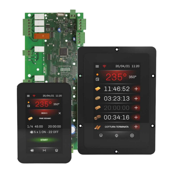
Product description Vcolor 388 is a controller for steam tube deck ovens which have a centralised gas burner heating system. The controller has an open frame board and a remote user interface which consists of a 5-inch (M) or 7-inch (L) capacitive TFT touch-screen graphic display in glass which is installed vertically, either semi-recessed into the front or flush with the panel. -
Page 5: Models Available And Technical Features
EVCO S.p.A. Vcolor 388 | Installer manual ver. 1.0 | Code 144VC388E104 Models available and technical features The table below shows the technical features of the models available. Optional expansion Vcolor 388 M & L modules with 2 relays (max. 2) - Page 6 EVCO S.p.A. Vcolor 388 | Installer manual ver. 1.0 | Code 144VC388E104 Configurable K8 (default sound) Configurable K9 (default burner power supply) Configurable K10 (default steam injection deck 1) Configurable K11 (default steam injection deck 2) Configurable K12 (default steam injection deck 3)
- Page 7 EVCO S.p.A. Vcolor 388 | Installer manual ver. 1.0 | Code 144VC388E104 Vcolor 388 M with J/K thermocouples Vcolor 388 M (control module + 5” user interface kit): EVCMC38FJ2E (flush fit installation from behind) EVCMC38FJ2EF (semi-recessed installation into the front) Vcolor 388 L (control module + 7”...
-
Page 8: Measurements And Installation
EVCO S.p.A. Vcolor 388 | Installer manual ver. 1.0 | Code 144VC388E104 MEASUREMENTS AND INSTALLATION Format features The control module is available in a split version with an open frame board. User interfaces are available in 5 or 7-inch versions for vertical operation and have capacitive colour TFT touch-screen graphic displays. - Page 9 EVCO S.p.A. Vcolor 388 | Installer manual ver. 1.0 | Code 144VC388E104 Vcolor 388L Page 9 of 44...
-
Page 10: User Interface Installation
EVCO S.p.A. Vcolor 388 | Installer manual ver. 1.0 | Code 144VC388E104 User interface installation Depending on the model, installation can be: flush, from behind the panel with threaded studs (not provided) welded to hold it in place; semi-recessed, from the front of the panel with spring clips to hold it in place. -
Page 11: Electrical Connection
EVCO S.p.A. Vcolor 388 | Installer manual ver. 1.0 | Code 144VC388E104 ELECTRICAL CONNECTION Vcolor 388M electrical connection The diagram below shows the electrical connection of the control device with a 5-inch user interface. N.B.: The USB communications port makes it possible to upload and download the device settings and personalise the graphics, recipes and languages using an ordinary USB flash drive (see section 10 “USING THE USB PORT”). -
Page 12: Vcolor 388L Electrical Connection
EVCO S.p.A. Vcolor 388 | Installer manual ver. 1.0 | Code 144VC388E104 Vcolor 388L electrical connection The diagram below shows the electrical connection of the control device with a 7-inch user interface. N.B.: The USB communications port makes it possible to upload and download the device settings and personalise the graphics, recipes and languages using an ordinary USB flash drive (see section 10 “USING THE USB PORT”). -
Page 13: Precautions For Electrical Connection
EVCO sales network. FIRST-TIME USE First-time use Proceed as follows: Install the device as shown in section 2 “INSTALLATION”, taking all the precautions mentioned in section 2.3 “Installation... -
Page 14: Operation
4 seconds to unlock the display. Splash screen When the control module is powered up, it boots up then defaults to the EVCO splash screen for a few seconds. Stand-by screen The device goes automatically from the splash screen to the stand-by screen. -
Page 15: Configuration Screen
EVCO S.p.A. Vcolor 388 | Installer manual ver. 1.0 | Code 144VC388E104 The current date and time are displayed, as well as the following keys: The “On/Off” key, which takes the device from stand-by to ON when held down The “Configuration”... -
Page 16: Delayed Start Screen
EVCO S.p.A. Vcolor 388 | Installer manual ver. 1.0 | Code 144VC388E104 N.B.: if a non-existent day of the month is set by mistake (e.g. 31/02), the change will not be accepted and the last date saved will be displayed. If a non-existent value is set for the month (above 12) or hour/minutes (above 23 for hours and 59 for minutes), the highest allowed value will automatically be displayed. - Page 17 EVCO S.p.A. Vcolor 388 | Installer manual ver. 1.0 | Code 144VC388E104 Press the arrows at the top of the screen to scroll through the days of the week. Two daily chamber setpoint programmes can be activated or deactivated for each day of the week, each with two scheduled start/end times.
-
Page 18: Home Screen
EVCO S.p.A. Vcolor 388 | Installer manual ver. 1.0 | Code 144VC388E104 When the controller is switched off, the stand-by screen displays the day and time of the closest delayed start. Home screen To go from the stand-by screen to the home screen, keep the key pressed down for a few seconds. -
Page 19: Change Chamber Setpoint Screen
EVCO S.p.A. Vcolor 388 | Installer manual ver. 1.0 | Code 144VC388E104 Image of the recipe set Timer to count down the cooking cycle (hh:mm:ss), which is white if the cycle is in progress and grey if not “+” symbol to access the deck settings. - Page 20 EVCO S.p.A. Vcolor 388 | Installer manual ver. 1.0 | Code 144VC388E104 On screen Settings/start-up screen Current chamber temperature Deck number and “back” key Image and name of loaded recipe Data of first phase (no cycle running) or cycle in progress...
- Page 21 EVCO S.p.A. Vcolor 388 | Installer manual ver. 1.0 | Code 144VC388E104 By pressing the name of the recipe, a preloaded image can be retrieved and a name entered using the keypad; by pressing on the line corresponding to each phase, a page will open where it is possible to set the time and, when outputs are appropriately configured, also the steam injection cycles and vent opening.
- Page 22 EVCO S.p.A. Vcolor 388 | Installer manual ver. 1.0 | Code 144VC388E104 Recipes stored in “Recipes” can also be copied in “My recipes”. To do this, access “Recipes” by pressing the key, select the desired recipe and press the key which will turn white ;...
- Page 23 EVCO S.p.A. Vcolor 388 | Installer manual ver. 1.0 | Code 144VC388E104 pressing the flashing icon next to the countdown. The end of the extra time will be signalled in the same way until the cycle is terminated by pressing the message.
-
Page 24: Managing Loads
EVCO S.p.A. Vcolor 388 | Installer manual ver. 1.0 | Code 144VC388E104 MANAGING LOADS Initial information The controller manages steam tube deck ovens (with 3-5 decks) which have a centralised gas burner heating system. Some functions are shared by all decks, while others are independent for each deck. A detailed list is given below: Shared functions •... -
Page 25: Venting
EVCO S.p.A. Vcolor 388 | Installer manual ver. 1.0 | Code 144VC388E104 Venting The “venting” function only operates if optional expansion modules with two relays are installed. It is possible to configure a relay to automatically open the vent on each deck by activating the ON/OFF valves. -
Page 26: List Of Configuration
EVCO S.p.A. Vcolor 388 | Installer manual ver. 1.0 | Code 144VC388E104 LIST OF CONFIGURATION PARAMETERS PARAM. MIN. MAX. M.U. DEF. ANALOGUE INPUTS type of probe J thermocouple (only for J/K power board) - - - K thermocouple (only for J/K power board) - Page 27 EVCO S.p.A. Vcolor 388 | Installer manual ver. 1.0 | Code 144VC388E104 PERSISTENCE – pressing and releasing the “MANUAL STEAM INJECTION” key will cause steam injection for the length of time the key is pressed only enable cyclical steam injection when the cooking timer starts up...
- Page 28 EVCO S.p.A. Vcolor 388 | Installer manual ver. 1.0 | Code 144VC388E104 PARAM. MIN. MAX. M.U. DEF. DIGITAL INPUTS polarity digital input safety thermostats for combustion fumes + cooking chamber (connected in series on input 51-52) - - - 0 = normally open (input active with contact closed)
- Page 29 EVCO S.p.A. Vcolor 388 | Installer manual ver. 1.0 | Code 144VC388E104 13 = Chamber light 14 = Venting deck 1 15 = Venting deck 2 16 = Venting deck 3 17 = Venting deck 4 18 = Venting deck 5...
- Page 30 EVCO S.p.A. Vcolor 388 | Installer manual ver. 1.0 | Code 144VC388E104 13 = DO NOT USE 14 = Venting deck 1 15 = Venting deck 2 16 = Venting deck 3 17 = Venting deck 4 18 = Venting deck 5...
-
Page 31: Alarm Management
EVCO S.p.A. Vcolor 388 | Installer manual ver. 1.0 | Code 144VC388E104 ALARM MANAGEMENT If an alarm situation occurs, the buzzer is activated and the alarm icon appears. Pressing this key will silence the buzzer and the page with the active alarms will automatically be displayed. - Page 32 EVCO S.p.A. Vcolor 388 | Installer manual ver. 1.0 | Code 144VC388E104 No communication alarm between the interface and the control module to correct: NO COMMUNICATION check the user interface-control module connection main results: the loads will be deactivated Incompatibility alarm between the interface and the control module...
- Page 33 EVCO S.p.A. Vcolor 388 | Installer manual ver. 1.0 | Code 144VC388E104 Fan motor block alarm To correct: check the fan motor. FAN MOTOR BLOCK Main results: the burner power supply relay, the heating relay and steam injection are deactivated, whereas the cycle, if running, continues.
-
Page 34: Connectivity
EVCO S.p.A. Vcolor 388 | Installer manual ver. 1.0 | Code 144VC388E104 CONNECTIVITY Initial information Users can interact remotely with their equipment and start up/stop working cycles using the EPoCA cloud platform with Wi-Fi or Ethernet connectivity (which also enable alternative or parallel control through MODBUS TCP). For more details, compare the connectivity options in the “Models available and technical features”... -
Page 35: Epoca Cloud Platform
HVAC units in response to market demand. To connect to the cloud system and remotely control machinery from a PC, tablet or smartphone, all users need is an EVCO controller with native EPoCA®... -
Page 36: Using The Usb Port
EVCO S.p.A. Vcolor 388 | Installer manual ver. 1.0 | Code 144VC388E104 10 USING THE USB PORT 10.1 Initial information Uploading and downloading can be carried out through the USB port on the user interface. Uploading means transferring data from a USB flash drive to the display and downloading transferring data from the display to the USB flash drive. -
Page 37: Accessories
EVCO S.p.A. Vcolor 388 | Installer manual ver. 1.0 | Code 144VC388E104 11 ACCESSORIES 11.1 2 relay expansion EVCLE322XXE Expansion module with 2 electro-mechanical relays, 5 A res. @ 250 Vac type SPST 11.2 Safety transformer ECTSFD004 The transformer can power the user interface. -
Page 38: Buzzer Expansion
Internet using the EPoCA® cloud system. 11.9 EV3 Web gateway EV3W01 IoT gateway with Ethernet connectivity and data logging functions to remotely monitor and control an RS-485 MODBUS RTU network with up to 10 EVCO controllers with EPoCA® technology using the EPoCA® cloud platform. page... -
Page 39: Technical Specifications
EVCO S.p.A. Vcolor 388 | Installer manual ver. 1.0 | Code 144VC388E104 12 TECHNICAL SPECIFICATIONS 12.1 Technical data Purpose of the control device: function controller Construction of the control device: built-in electronic device user interface control module Housing: plastic housing... - Page 40 EVCO S.p.A. Vcolor 388 | Installer manual ver. 1.0 | Code 144VC388E104 user interface control module Power supply: 12 Vac (±15%), 50/60 Hz (±3 Hz), powered by the control module 20 VA max. Rated impulse withstand voltage: 4 KV Overvoltage category:...
- Page 41 EVCO S.p.A. Vcolor 388 | Installer manual ver. 1.0 | Code 144VC388E104 13 electro-mechanical relay outputs (configurable): - 1 5 A res. @ 250 Vac type SPST (K1) output - 1 5 A res. @ 250 Vac type SPST (K2) output - 1 5 A res.
- Page 42 EVCO S.p.A. Vcolor 388 | Installer manual ver. 1.0 | Code 144VC388E104 Notes ____________________________________________________________________________________________________________ ____________________________________________________________________________________________________________ ____________________________________________________________________________________________________________ ____________________________________________________________________________________________________________ ____________________________________________________________________________________________________________ ____________________________________________________________________________________________________________ ____________________________________________________________________________________________________________ ____________________________________________________________________________________________________________ ____________________________________________________________________________________________________________ ____________________________________________________________________________________________________________ ____________________________________________________________________________________________________________ ____________________________________________________________________________________________________________ ____________________________________________________________________________________________________________ ____________________________________________________________________________________________________________ ____________________________________________________________________________________________________________ ____________________________________________________________________________________________________________ ____________________________________________________________________________________________________________ ____________________________________________________________________________________________________________ ____________________________________________________________________________________________________________ ____________________________________________________________________________________________________________ ____________________________________________________________________________________________________________ ____________________________________________________________________________________________________________ ____________________________________________________________________________________________________________ ____________________________________________________________________________________________________________ ____________________________________________________________________________________________________________ ____________________________________________________________________________________________________________ ____________________________________________________________________________________________________________...
- Page 43 EVCO. The customer (manufacturer, installer or end user) assumes all responsibility for the configuration of the device. EVCO accepts no liability for any possible errors in this document and reserves the right to make any changes at any time without prejudice to the essential functional and safety features of the equipment.
- Page 44 EVCO S.p.A. Vcolor 388 | Installer manual ver. 1.0 | Code 144VC388E104 EVCO S.p.A. Via Feltre 81, 32036 Sedico Belluno ITALY Tel. +39 0437/8422 | Fax +39 0437/83648 info@evco.it | www.evco.it page...
Need help?
Do you have a question about the Vcolor 388 and is the answer not in the manual?
Questions and answers