
Related Manuals for Johnson Controls YORK YVAM 0350


Summary of Contents for Johnson Controls YORK YVAM 0350
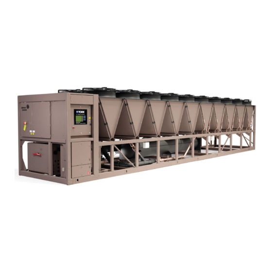
- Page 1 YVAM Control Center Centrifugal Liquid Chiller with R-134a Refrigerant Operation and Maintenance Form Number: 160.88-OM1 (122) Issue Date: 2022-01-14 New Release...
- Page 2 YVAM Control Center...
-
Page 3: Table Of Contents
Contents General safety guidelines..........................7 C o n t e n t s Safety symbols............................7 Changeability of this document......................8 Associated literature..........................8 Conditioned based maintenance......................8 Nomenclature............................9 System fundamentals............................ 11 System components..........................11 Compressor..............................12 Motor................................13 Heat exchangers............................13 Evaporator..............................13 Condenser..............................13 Waterboxes.............................. - Page 4 OptiView control center functions and navigation..................30 Display only............................30 Programmable............................. 30 Access level..............................30 Change setpoints............................30 Programming setpoints..........................31 Manual controls............................31 Free cursor..............................31 Navigation............................31 Languages............................32 Analog input ranges..........................32 OptiView screens..........................34 Home screen...............................34 System screen.............................36 Evaporator screen............................
- Page 5 Master slot numbers list........................83 Display messages..........................88 Status messages............................88 Run messages............................89 MBC startup messages..........................90 Start inhibit messages..........................90 Warning messages............................ 90 Routine shutdown messages........................93 Cycling shutdown messages........................94 Safety shutdown messages........................101 Drive operation.............................111 OptiSpeed compressor drive overview...................111 OptiSpeed compressor drive features....................
- Page 6 Chemical water treatment........................136 Cleaning evaporator tubes........................137 Tube fouling..............................137 Tube cleaning procedures........................137 Evaporator tube leaks..........................138 Testing for evaporator tube leaks......................138 Condenser maintenance........................139 Cleaning requirements of microchannel heat exchangers..............139 Cleaning Standard and Environment Guard MCHX coils..............139 Cleaning Environment Guard Premium MCHX coils................140 Electrical controls..........................140 Unit heater operation verification....................
-
Page 7: General Safety Guidelines
General safety guidelines Important: Read before proceeding. This equipment is a relatively complicated apparatus. During rigging, installation, operation, maintenance, or service, individuals may be exposed to certain components or conditions including, but not limited to: heavy objects, refrigerants, materials under pressure, rotating components, and both high and low voltage. -
Page 8: Changeability Of This Document
Johnson Controls makes no commitment to update or provide current information automatically to the manual owner. Updated manuals, if applicable, can be obtained by contacting the nearest Johnson Controls Service office or accessing the Johnson Controls Knowledge Exchange website at https://docs.johnsoncontrols.com/... -
Page 9: Nomenclature
Nomenclature Figure 1: System nomenclature Figure 2: Compressor nomenclature Figure 3: Vessel nomenclature YVAM Control Center... - Page 10 Figure 4: Variable speed drive nomenclature YVAM Control Center...
-
Page 11: System Fundamentals
System fundamentals The following section contains information about the system components and operation of the YORK Model YVAM™ Centrifugal Liquid Chiller. ® System components The YORK Model YVAM Centrifugal Liquid Chiller is completely factory-packaged and includes the following components: • Evaporator •... -
Page 12: Compressor
Figure 6: Compressor side view Callout Component Callout Component Evaporator Motor cooling filter drier Expansion valve Cooling piping for variable speed drive Eaton surge suppressor Direct drive motor and MBC ® Compressor Figure 7: Variable speed drive end view Callout Component Callout Component... -
Page 13: Motor
Motor The compressor motor is a hermetic permanent magnet high-speed design with magnetic bearings. The compressor impeller is overhung from the end of the motor shaft and has no bearings of its own. The motor includes angular contact ball bearings only engaged with the rotor shaft during shutdown after rotation is stopped or during shutdown due to loss of power to the magnetic bearings. -
Page 14: Variable Speed Drive
Variable speed drive The variable speed drive is factory packaged with the chiller. It is designed to vary the compressor motor speed by controlling the frequency and voltage of the electrical power to the motor. The control logic automatically adjusts motor speed as required to suit lift and capacity requirements. Power panel The power panel includes the uninterrupted power supply and power storage battery. - Page 15 Figure 8: System piping and instrumentation diagram (P&ID) YVAM Control Center...
- Page 16 Table 2: Legend for system piping and instrumentation diagram Device Description ABV-1 Actuated butterfly valve - VSD cooling valve EEV-1 Condenser liquid line drain valve - motorized butterfly valve FS-1 Evaporator water flow switch FST-1 Fluid strainer - VSD cooling strainer HPS-1 Compressor high pressure cut-out switch HTR-1...
-
Page 17: Optiview Control Center
OptiView control center The YORK OptiView control center LCD graphic display and keypad is the interface for starting, stopping, configuring, monitoring, and commanding the chiller controls. The control center is a microprocessor-based system for centrifugal chillers. It controls the leaving chilled liquid temperature (LCHLT) and maintains safe operation. - Page 18 Building Automation System (BAS) allows increased remote control of the chiller, including 24-hour performance monitoring by a remote site. An optional circuit board called the SC-EQUIP provides Johnson Controls and YORK mechanical equipment such as the YVAM chiller with BAS networking connectivity.
-
Page 19: System Operation Description
Some screens, displayed values, programmable setpoints, and manual controls exist for service technician use only. They are only displayed when logged in at Service access level or higher. The setpoints and parameters displayed on these screens are explained in detail in YORK YVAM Service Manual (Form 160.88-M2). -
Page 20: Anti-Surge Minimum Frequency
Reduced speed also reduces the available capacity of the chiller, when speed reduction is possible. If speed is reduced, the chiller power use is reduced. As a result, at reduced capacity requirements where condenser pressure is also reduced, the motor speed is reduced as much as possible while maintaining chilled liquid temperature and sufficient lift. -
Page 21: Surge Protection
Surge protection The surge protection feature detects surge events. It provides a running count of the surges detected over the lifetime of the chiller. It allows the user to define how many surges are excessive and how the control reacts to an excess surge condition. When excessive surging is detected, this feature can shut down the chiller. -
Page 22: System Operating Procedures
Microcomputer Control Center pump run contacts, the pump automatically starts, and so this step is not necessary. Note: The coolant temperature inside any Johnson Controls-supplied liquid-cooled motor starter must be maintained above the dewpoint temperature in the equipment room to prevent condensing water vapor inside the starter cabinet. -
Page 23: Chiller Operation
• Condenser liquid flow is established • No uncleared faults or start inhibits exist Chiller operation Upon start request, the following occur in sequence: Chiller's system pump run contacts close Variable speed drive pre-charges (approximately 12 seconds) Variable speed drive pre-regulates (approximately 3 seconds) Motor runs The chiller varies capacity to maintain the leaving chilled liquid temperature setpoint by a specific sequencing of optional hot gas bypass, variable geometry diffuser, and compressor speed. - Page 24 Table 5: Temperature setpoint Control source Leaving Chilled Liquid Temperature setpoint Local Leaving Chilled Liquid Temperature setpoint, entered from the panel. It is programmable over the range of 38.0°F to 70.0°F (3.3°C to 21.1°C) for water or Local 10.0°F to 70.0°F (-12.2°C to 21.1°C) for brine. If Smart freeze is enabled, the range is 36.0°F to 70.0°F (2.2°C to 21.1°C) for water.
-
Page 25: Automatic Temperature Shutdown
Automatic temperature shutdown The Leaving Chilled Liquid Temperature Cycling Offset, Shutdown setting on the panel can be programed to set the temperature below the LCHLT setpoint at which the chiller automatically cycles off when the load is less than the chiller minimum capability. This setting defines the temperature offset below the LCHLT setpoint where shutdown is expected. -
Page 26: Stopping The System
Figure 10 shows an example log sheet used by Johnson Controls Personnel for recording test data on chiller systems. Log sheets are available in pads of 50 sheets and can be obtained through the nearest Johnson Controls office. -
Page 27: Fault Shutdowns
Note: A pad of 50 log sheets can be ordered from your local Johnson Controls branch by requesting Form 160.88-MR1. An accurate record of readings serves as a valuable reference for operating the system. Readings taken when a system is newly installed establish the normal conditions with which to compare later readings. - Page 28 of subfreezing ambient temperatures, then one of the following freeze protection protocols must be followed: • An appropriate freeze protection fluid selected for the lowest possible ambient temperatures must be used in the chilled fluid circuit. -OR- • The fluid in the evaporator must be drained as follows: Remove power to the waterbox heaters.
-
Page 29: Physical Data
50% of the minimum are permitted. Glycol limits are higher. Contact your Johnson Controls sales office for ratings and further information. Shipping and operating weights are shown for the base unit. Selected options can add weight. Contact your nearest Johnson Controls sales office for weight data. YVAM Control Center... -
Page 30: Optiview Control Center Functions And Navigation
OptiView control center functions and navigation Each screen description in this section begins with an overview that describes the graphical elements on the screen and gives a short summary of the functions available. Each element on the screen is then categorized into three distinct groups: Display Only, Programmable, and Navigation. The following section provides a short description of what types of information are included in these groups. -
Page 31: Programming Setpoints
prompt described previously. It allows the user to log on at a higher access level without returning to the Home screen. After logging on, the user can then modify setpoints on that screen. Programming setpoints About this task: The control center uses the setpoint values to control the chiller and other devices that are connected to the chiller system. -
Page 32: Languages
Figure 11: Screen layout and navigation Languages The screens can be displayed in various languages. Language selection is performed on the User screen. The preferred language is selected from those available. Not all languages are available. English is the default language. If a language other than English is displayed, an English-speaking person should navigate to the User screen using the preceding Navigation chart and select English. - Page 33 Table 9: Analog input ranges English range Metric range Analog input High Units High Units Leaving Chilled Liquid Temperature 82.0 °F -17.7 27.7 °C Return Chilled Liquid Temperature 94.1 °F -17.7 34.5 °C Leaving Condenser Liquid Temperature 133.5 °F -13.3 56.3 °C Return Condenser Liquid Temperature...
-
Page 34: Optiview Screens
OptiView screens Home screen Figure 12: Home screen When the chiller system is powered on, the default display in Figure 12 appears. The Home screen display depicts a visual representation of the chiller itself. The animation indicates the chilled liquid flow and condenser cooling liquid flow when the flow switch inputs are satisfied. - Page 35 Table 11: Programmable Button Access Description Clear Fault View When safety conditions are detected, the chiller shuts down, and the main status display of the chiller displays a message to indicate the cause of the shutdown. Use this button to clear the fault and message after the condition is removed. The button only shows when the condition can be cleared.
-
Page 36: System Screen
System screen Figure 13: System screen This screen gives a general overview of common chiller parameters for both shells. Table 13: Display only fields Field/LED name Description Discharge Temperature Displays the temperature of the refrigerant in its gaseous state at discharge of the compressor as it travels to the condenser. -
Page 37: Evaporator Screen
Evaporator screen Figure 14: Evaporator screen This screen displays a cutaway view of the chiller evaporator. All setpoints relating to the evaporator side of the chiller are maintained on this screen. Animation of the evaporation process indicates whether the chiller is presently in a Run condition. Animation of the liquid flow indicates chilled liquid flow. - Page 38 Table 15: Display only fields Field/LED name Description Evaporator Refrigerant Temperature Displays the temperature of the refrigerant in the evaporator when Refrigerant is set to Enable. Evaporator Freeze Protection LED LED is on when the Evaporator Freeze Protection is in effect. Evaporator Refrigerant Temperature Displays the Evaporator Refrigerant Temperature.
-
Page 39: Condenser Screen
Condenser screen Figure 15: Condenser screen This screen displays the air-cooled condenser with an animation of heat ejection out of the fan deck. Table 18: Display only fields Field/LED name Description Condenser Saturation Temperature Displays the saturation temperature in the condenser. Condenser Small Temperature Displays the condenser small temperature difference. -
Page 40: Compressor Screen
Compressor screen Figure 16: Compressor screen This screen displays a cutaway view of the chiller compressor, revealing the impeller, and shows all conditions associated with the compressor. Animation of the compressor impeller indicates whether the chiller is presently in a Run condition. This screen also serves as a gateway to subscreens for navigating to capacity control and displaying MBC, surge, and VGD and power panel detail. - Page 41 Table 21: Navigation Button Description Moves to the subscreen that allows viewing and calibrating the VGD feature. Programming requires a Service access level. Motor Details Moves to the screen showing motor operating details. Power Panel Moves to the subscreen that allows viewing power panel status and parameters YVAM Control Center...
-
Page 42: Magnetic Bearing Controller Screen
Magnetic bearing controller screen Figure 17: Magnetic bearing controller screen This screen displays the orientation of the magnetic bearing axes relative to the compressor driveline. Pertinent parameters transmitted to the control panel from the Magnetic Bearing Controller (MBC) are displayed on this screen. Many parameters are shown in the diagram in the locations they represent. - Page 43 Table 22: Display only fields Field/LED name Description V4 (Current) Displays the magnetizing current to the lower bearing on the radial axis designated “V” for the Opposite Impeller End. Z2 (Current) Displays the magnetizing current to the axial bearing at the Opposite Impeller End. MBC Control Mode Displays whether the MBC is in Manual or Automatic Control.
-
Page 44: Magnetic Bearing Controller Details Screen
Magnetic bearing controller details screen Figure 18: Magnetic bearing controller details screen This screen displays the orientation of the magnetic bearing axes relative to the compressor driveline similar to the MBC screen. Additional pertinent parameters transmitted to the control panel from the MBC are displayed on this screen. Many parameters are shown in the diagram in the locations they represent. - Page 45 Table 24: Display only fields Field/LED name Description [MBC Status] ABS (LED) Indicates the MBC is reporting its automatic balancing system feature is active via Modbus Data. Motor Speed Indicates the compressor motor rotational speed. DC Bus Voltage Indicates the voltage of the DC Bus, which supplies the MBC. MBC Operation Time Indicates the cumulative time of operation of the MBC since initial power up.
-
Page 46: Surge Screen
Surge screen Figure 19: Surge screen overview This screen displays the chiller compressor and all parameters relating to the surge protection feature. All setpoints relating to this screen are maintained on this screen. Table 26: Display only fields Field/LED name Description Delta P/P A parameter that represents the system differential or head pressure. - Page 47 Table 27: Programmable Button Access Description Shutdown (Enabled/Disabled) Operator Allows the user to select if the chiller shuts down or continues to run when an excess surge situation is detected. Count Window Operator Allows the user to define the period of time (1 to 5 minutes; default 3) in which the number of surge events (Surge Window Count) are compared to the maximum allowed (Count Limit), for the purpose of detecting an excess surge situation.
-
Page 48: Variable Geometry Diffuser Screen
Variable geometry diffuser screen Figure 20: Variable geometry diffuser screen This screen displays information pertinent to the VGD operation. Table 29: Display only fields Field/LED name Description Active Stall Voltage Displays the stall detector output voltage (x.xxVdc), as received by the microboard, from the stall board. -
Page 49: Power Panel Screen
Power panel screen Figure 21: Power panel screen This screen displays information pertaining to the power panel, which includes the uninterruptable power supply (UPS) and storage battery for essential loads necessary for shutdown during a line power loss. Table 31: Display only fields Field/LED name Description Control Voltage (LED) - Page 50 Table 32: Navigation Button Description Home Causes an instant return to the Home screen. Compressor Causes an instant return to the Compressor screen. Causes an instant return to the Variable Speed Drive screen. YVAM Control Center...
-
Page 51: Capacity Control Screen
Capacity control screen Figure 22: Capacity control screen This screen displays the pertinent parameters associated with capacity control in relation to Leaving Chilled Liquid temperature, current and pressure overrides, and anti-surge control. This screen also provides a means for a service technician to control VGD, speed, and optional hot gas bypass valve manually for maintenance or service. - Page 52 Table 33: Display only fields Field/LED name Description Delta T Displays the difference between the temperature of the chilled liquid leaving the evaporator and the Leaving Chilled Liquid Active setpoint. Control State Displays the present source controlling the command to the capacity control devices, based on conditions as follows: •...
-
Page 53: Variable Speed Drive Screen
Variable speed drive screen Figure 23: Variable speed drive screen This screen displays information pertaining to the variable speed drive. Table 35: Display only fields Field/LED name Description Motor Run (LED) Indicates whether the digital output from the controls is commanding the motor to RUN. VSD Fault (LED) Indicates that the variable speed drive is reporting a fault over the communications link or by logic low at the hardwired digital input. - Page 54 Table 35: Display only fields Field/LED name Description Voltage Total Harmonic Displays the Total Harmonic Distortion (THD) for each of the voltage lines as calculated by Distortion - (L1, L2, L3) the VSD. Input Current Total Demand Displays the Total Dynamic Distortion (TDD) for each of the supply current lines as calculated Distortion - (L1, L2, L3) by the variable speed drive.
-
Page 55: Variable Speed Drive (Vsd) Details Screen
Variable speed drive (VSD) details screen Figure 24: Variable speed drive (VSD) details screen This screen displays more detailed parameters associated with the variable speed drive. This screen also provides a means for a service technician to access setpoints or control the DC Bus manually for maintenance or service. - Page 56 Table 38: Display only fields Field/LED name Description VSD Control State Displays the control state of the variable speed drive. States are as follows: • 0 = Idle • 1 = Precharge • 2 = Pre-Regulate • 3 = Waiting for Run •...
-
Page 57: Vsd Cooling Screen
VSD cooling screen Figure 25: VSD cooling screen Table 41: Display only fields Field/LED name Description VSD HX Approach Temp Displays the drive HX approach temperature warning offset setpoint. Warning Offset VSD HX Approach Temp Fault Displays the drive HX approach temperature fault offset setpoint. Offset Auxiliary VSD Cooling Offset Displays the auxiliary drive cooling offset setpoint. -
Page 58: Motor Details Screen
Motor details screen Figure 26: Motor details screen This screen displays information pertinent to the motor temperature monitoring feature. The feature consists of motor winding temperature and motor housing temperature. The individual winding temperature sensors can be disabled on this screen. Table 42: Display only fields Field/LED name Description... - Page 59 Table 42: Display only fields Field/LED name Description Ambient Dew Point When the optional Ambient Dew Point Temperature sensor is enabled, its reading is Temperature indicated here. Motor Cooling Valve Output to the motor cooling valve in percent from 0%, closed, to 100% opened. Command Motor Cooling Control State Displays whether the motor cooling valve is in auto or manual control.
-
Page 60: Setpoints Screen
Setpoints screen Figure 27: Setpoints screen This screen provides a convenient location for programming the most common setpoints involved in the chiller control. This screen also serves as a gateway to the Setup screen for defining the setup of general system parameters. Table 44: Display only fields Field/LED name Description... - Page 61 Table 45: Programmable Button Access Description Local Leaving Chilled Liquid Operator This value allows the user to define the Leaving Chilled Liquid Temperature Temperature - Setpoint that is to be maintained by the chiller. It is programmable over the range of 38.0°F to 70.0°F (water) or 10.0°F to 70.0°F (brine).
-
Page 62: Remote Control Screen
Remote control screen Figure 28: Remote control screen This screen allows the user to use remote control status and change certain setpoints. Table 47: Display only fields Area Field/LED name Description Active Run Command LED Indicates active run command Local Run Command LED Indicates local run command Run / Stop Control Remote Run Command LED... - Page 63 Table 48: Programmable Button Access Description Select Run/ Stop Operator and Allows the user to selected the Control Source for the run/stop command above (Local, BAS, Hardwire). Select Cooling Operator and Allows the user to select the Control Source for cooling control (Local, BAS, above Hardwire).
-
Page 64: Setup Screen
Setup screen Figure 29: Setup screen This screen is the top level of the general configuration parameters. It allows programming of the time and date, along with specifications as to how the time is displayed (12 hour or 24 hour format). In addition, the chiller configuration, as determined by the state of the microboard program jumpers and program switches is displayed. - Page 65 Table 51: Programmable Button Access Description Present Date Operator Allows the user to specify the present date. This value is critical to logging system shutdowns accurately and for using the scheduling capabilities. When prompted to enter a date value, the user must enter the day, month, and four-digit year (using leading zeroes as necessary).
-
Page 66: Schedule Screen
Schedule screen Figure 30: Schedule screen The schedule screen contains more programmable values than a normal display screen. Each programmable value is not linked to a specific button. Instead the Select button is used to enable the cursor arrows, which are used to highlight the day and the start or stop time the user wants to modify. - Page 67 Table 53: Programmable Button Access Description Reset All Exception Days Operator Deletes all programming for exception days within the next six weeks. Select Operator Places a selection box around a start time for a given day. Use ◄ , ► , ▲ or ▼...
-
Page 68: User Screen
User screen Figure 31: User screen Use this to define custom User IDs and matching passwords. The building administrator can then assign custom passwords to users who are authorized to maintain the chiller. This screen displays attributes assigned to User IDs. There are no other display options. Table 55: Programmable Button Access... -
Page 69: Comms Screen
Comms screen Figure 32: Comms screen This screen allows definition of the necessary communications parameters. See Printing for details on the printer connections and setup. Presently, there are no COM 2 communications features available. This screen displays attributes assigned to COMMS IDs. There are no other display options. Table 57: Programmable Button Description... -
Page 70: Printer Screen
Printer screen Figure 33: Printer screen This screen allows definition of the necessary communications parameters for the printer. See Printing for details on printer connections and setup. Table 59: Display only fields Field/LED name Description Time Remaining Until Next Displays the time until the next print log will occur, if the function is enabled. Print Table 60: Programmable Button... -
Page 71: Sales Order Screen
This screen allows definition of the sales order parameters. The commissioning date is entered by the YORK/Johnson Controls service technician at the time of chiller commissioning. These values must never be changed or entered by anyone other than a qualified service technician. Entry instructions are included in the YORK YVAM Service Manual (Form 160.88-M2). -
Page 72: Operations Screen
Operations screen Figure 35: Operations screen This screen allows definition of general parameters having to do with the operation of the chiller. Table 65: Display only fields Field/LED name Description Chiller Run Time Displays the amount of time the chiller has been running since the last start signal was received. -
Page 73: History Screen
History screen Figure 36: History screen This screen allows the user to browse through the faults. For a more thorough reporting of the system conditions at the time of the recorded shutdown, use the History details screen. Table 67: Display only fields Field/LED name Description Last Normal Shutdown... -
Page 74: History Details Screen
History details screen Figure 37: History details screen This screen allows the user to see an on-screen printout of all the system parameters at the time of the selected shutdown. Not all screens are shown as in Figure 37. The number of screens required to display all of the data varies according to type of motor starter and options applied. -
Page 75: Custom Screen
Custom screen Figure 38: Custom screen This screen allows up to 10 service technician selected parameters to be displayed. These parameters are selected from a list on the Custom setup screen. This allows the service technician to display parameters pertinent to a particular problem during troubleshooting. At completion of the service call, the display can be cleared or the parameters can be left there for monitoring by operations personnel. -
Page 76: Custom Setup Screen
Custom setup screen Figure 39: Custom setup screen This screen allows the service technician to select up to 10 parameters for display on the Custom screen. Table 75: Display only fields Field/LED name Description Slot Numbers Lists the available parameters that can be displayed. The required parameters for display are selected from this list. -
Page 77: Trend Screen
Trend screen Figure 40: Trend screen The Trend screen displays the graphical trending of the selected parameters and is also a gateway to the graph setup screens. You can plot up to six operator selected parameters (data points) in an X/Y graph format. The X-axis scales to the selected data collection interval and displays in a time of day or elapsed time format, as selected with the X-axis toggle button. - Page 78 Table 78: Programmable Button Description Start Access level required: Operator Pressing this button clears the graph, starts a new graph, sets the time of day to the present clock time, and begins the trending. This button is only available if trending is stopped. If the selected chart type is Triggered and Trigger Action is set to Start, data collection will not begin until the triggers have been satisfied and any selected trigger delay has elapsed.
-
Page 79: Trend Setup Screen
Trend setup screen Figure 41: Trend setup screen This screen is used to configure the trending screen. The parameters to be trended are selected from the Common Slots Screen or Common Slots Master list and entered as Slot Numbers for Data Points 1 through 6. - Page 80 Table 80: Programmable Button Access Description Data Point Min (1-6) Operator This button is only displayed if the Associated Slot Number is not 0. This is the minimum value displayed for the Y-axis. If you select a parameter for a data point, this value sets to the default value, which is the lowest value allowed for that parameter.
- Page 81 Table 81: Navigation Button Description Home Returns to the Home screen. Trending Returns to the Trending screen. Slot Numbers Displays a subscreen that lists the slot numbers of the most commonly monitored parameters. The preferred parameters to be plotted are selected from this screen. Triggers Displays the Advanced trend setup screen, where the start and stop triggers can be setup.
-
Page 82: Common Slots Screen
Common slots screen Figure 42: Common slots screen This screen displays the slot numbers of the commonly monitored parameters. The slot numbers for the remainder of the available parameters are listed on the Master slot numbers list From these lists, select up to six parameters to be trended. Return to the Trend setup screen and enter the parameters Slot Numbers into Data Points 1 through 6. -
Page 83: Master Slot Numbers List
Master slot numbers list The following table is the master slot number list for use with the Trend feature. Slot number Description System Chiller Operating State Coastdown Time Remaining Safety Relay Cycling Relay Warning Relay Operating Hours Run Time (in seconds) Number Of Starts Run Permissive Remote Ready To Start... -
Page 84: Refrigerant Level 0.0
Slot number Description 2057 High Pressure Switch 28716 Heating Shutdown Temperature 28718 Heating Delta T 28719 Active Heating Setpoint Subcooling 2059 Sub Cooling Temperature Drop leg refrigerant 2061 Drop Leg Refrigerant Temperature Compressor 1296 Discharge Temperature 1299 Discharge Superheat Surge 1813 Delta P / P 8236... - Page 85 Slot number Description 2306 Motor % FLA 3047 VSD Fault 18085 Input % Full Load Amps 2823 VSD Output Voltage 2822 VSD Output Frequency 20788 Max Chiller Frequency 2818 Input Power 2819 Input kW Hours 2878 L1 Voltage Total Harmonic Distortion 2879 L2 Voltage Total Harmonic Distortion 2880...
-
Page 86: Motor Housing Temperature
Slot number Description 3064 Motor Winding Phase C Temp Z2 End 19148 Average Winding Temperature 2362 Motor Housing Temperature 18361 Motor Housing Temperature Setpoint 18371 Motor Winding Temperature Setpoint 18362 Motor Cooling Valve Command 18396 Motor Cooling Control State 18397 Estimated Rotor Temperature 18398 Ambient Dew Point Temperature... - Page 87 Slot number Description 21018 Current Z1A 21019 Current Z2A 21020 Z1 Temperature 21021 Z2 Temperature 21022 MBC Amplifier Temp 21024 Rotor Elongation 21025 Motor Speed 21041 MBC Fault 21042 First Alarm Code 21043 Rotation Allowed 21045 Control Mode 21072 VW13 Soft Landing Counter 21073 VW24 Soft Landing Counter 21074...
-
Page 88: Display Messages
Display messages The Status Bar of the display contains a Status Line and, beneath it a Details Line. The Status Line contains a message that describes the operating state of the chiller, for example if it is stopped, running, starting, or shutting down. The Details Line displays Warning, Cycling, Safety, Start Inhibit, and other messages that provide further details of the Status Bar messages. -
Page 89: Run Messages
Table 85: Status messages Message Description The chiller is shut down but will initiate start upon receipt of a Local or Remote start signal. The Magnetic Bearing Controller (MBC) does not have the driveline rotor levitated. The Hot Gas Bypass Valve position (if present) is set to the programmed Hot Gas Startup Position. SYSTEM READY TO START The Level Control Valve position is set to the programmed Condenser Level Control Valve Startup Position. -
Page 90: Mbc Startup Messages
MBC startup messages Table 87: MBC startup messages Message Description The chilled liquid or condenser flow switch input is not reading voltage indicating no WAITING FOR FLOW presence of flow from the flow switch. Indication of flow is required during the MBC Startup state to allow transition to chiller run. - Page 91 Table 89: Warning messages Message Description The Evaporator pressure has decreased to the Warning threshold. This threshold is fixed in Water cooling applications. In Brine cooling applications, the threshold is a fixed amount above the programmable safety shutdown threshold. The Safety threshold in Brine applications is determined by the Brine solution and is determined by the YORK Factory.
- Page 92 Table 89: Warning messages Message Description During the time the MBC Rotation Mode is commanded ON by the microboard via serial comms this warning is set if the MBC reports Rotation Mode is OFF by serial comms. This WARNING – MBC – ROTATION warning is inhibited if MBC communication is not initiated and during the first 15 seconds MODE OFF after the Rotation Mode is commanded ON.
-
Page 93: Routine Shutdown Messages
Table 89: Warning messages Message Description This auto reset warning is set when all of the following are true: • Control Voltage digital input is high (indicates line power is available) WARNING – UPS – LINE LOW • Battery Voltage < Line Low Battery Voltage Threshold BATTERY VOLTAGE It releases when Battery Voltage >... -
Page 94: Cycling Shutdown Messages
Cycling shutdown messages For cycling shutdown messages, the chiller automatically restarts when the cycling condition clears. Table 91: Cycling shutdown messages Message Description The Chilled Liquid Flow Switch has remained open for 5 continuous seconds while the chiller was running, in soft shutdown, or at least 45 seconds after MBC startup is initiated. CHILLED LIQUID –... - Page 95 Table 91: Cycling shutdown messages Message Description The optional brine freeze protection motorized isolation valves Close output is energized > 40 seconds, but the feedback from the valve limit switch does not indicate it closed for ISOLATION VALVES - NOT three continuous seconds.
- Page 96 Table 91: Cycling shutdown messages Message Description The MBC has measured shaft displacement is greater than 90 µm (90 micron) from center in the orthogonal radial axis designated V at the opposite-impeller end radial magnetic bearing during Levitation or Rotation mode over a 7 second window (approximately 2/3 MBC –...
- Page 97 Table 91: Cycling shutdown messages Message Description The MBC has measured shaft displacement is greater than 100 µm (100 micron) axially from the design running position (approximately 1/2 of the air gap space to the touchdown bearing axially). The MBC Fault contacts open. The MBC remains in Levitation MBC –...
- Page 98 Table 91: Cycling shutdown messages Message Description The variable speed drive contains two temperature sensors, which monitor the unit’s internal ambient temperature. This shutdown is generated when the higher of the two ambient temperatures exceeds a high limit of 158°F (70°C). The unit’s fan(s) and water VSD –...
- Page 99 Table 91: Cycling shutdown messages Message Description This shutdown is generated if a communications problem occurs between the two VSD – LOGIC BOARD microprocessors on the drive logic board. PROCESSOR This shutdown is generated any time after the pre-regulation state has generated the correct DC link voltage setpoint and then the DC link voltage drops to a minimum value.
- Page 100 Table 91: Cycling shutdown messages Message Description The drive must be able to determine the input voltage frequency from the input voltage measurement. If the input voltage frequency is not stable enough for the drive to make VSD – PHASE LOCKED LOOP this determination, then this shutdown is generated.
-
Page 101: Safety Shutdown Messages
Table 91: Cycling shutdown messages Message Description The drive has shut down the chiller and the control center has not yet received the cause of the fault from the variable speed drive from the serial communications link. The variable speed drive shuts down the chiller by opening the Motor Controller VSD VSD SHUTDOWN –... - Page 102 Table 92: Safety shutdown messages Message Description The line power input signal at I/O board TB3-81 was low for 1 second continuous. This signal is used to determine when the digital inputs are affected by a line power loss versus an actual condition CONTROL PANEL –...
- Page 103 Table 92: Safety shutdown messages Message Description A possible defective Evaporator pressure Transducer or Leaving Chilled Liquid temperature Thermistor has been detected. The pressure and temperature that these devices are indicating are not in the correct relationship to each other. The control center converts the evaporator pressure to EVAPORATOR –...
- Page 104 Table 92: Safety shutdown messages Message Description This Safety Shutdown is set when the MBC determines a lapse in internal microprocessor activity on the Control Board through its Watchdog device. The MBC Fault contacts open. The MBC does not react to a levitation mode change command through serial comms. The MBC remains in the levitation MBC –...
- Page 105 Table 92: Safety shutdown messages Message Description This Safety Shutdown is set when the MBC determines the rotor speed exceeds the programmed setpoint of 360 Hz for 0.1 seconds continuous. Rotor speed is transmitted to the MBC from the VSD. The MBC Fault contacts open.
- Page 106 Table 92: Safety shutdown messages Message Description This safety shutdown occurs when any of the enabled motor winding temperatures exceeded the programmed High Winding Temperature Shutdown Threshold of 302˚F (150˚C) for 3 continuous MOTOR – seconds. The chiller can be started after all winding temperatures decreased to at least 18˚F (10˚C) HIGH WINDING below the shutdown threshold and the compressor is stopped.
- Page 107 Table 92: Safety shutdown messages Message Description This message applies only if the Surge Protection Shutdown feature is enabled. SURGE PROTECTION The Surge Window Count surge events exceeded the Count Limit setpoint. The chiller shuts down as – EXCESS SURGE soon as the count exceeds the limit.
- Page 108 Table 92: Safety shutdown messages Message Description This message is generated when the sum of the three phases of instantaneous input current values are greater than the shutdown value for a period of 1 second for the given model of drive listed in the following table.
- Page 109 Table 92: Safety shutdown messages Message Description The input current overload value is variable based on the Input Job Full Load Amps value programmed at the Control Panel. The input current overload value is 1.16 times the Input Job Full Load Amps value, but not to exceed the value for the given model of drive listed in the following table.
- Page 110 Table 92: Safety shutdown messages Message Description VSD – PHASE B See the previous message, VSD – PHASE A INPUT DCCT. INPUT DCCT VSD – PHASE C See the previous message, VSD – PHASE A INPUT DCCT. INPUT DCCT The motor current in each phase of the drive is measured at the beginning of the run command. The motor current at this time should measure very low.
-
Page 111: Drive Operation
Drive operation OptiSpeed compressor drive overview The new YORK OptiSpeed Compressor Drive (OSCD) is specifically designed for the application of ® driving a permanent magnet high speed motor with magnetic bearings used on the YORK Model YVAM Centrifugal Air-Cooled Chiller. This type of design allows the chiller to be designed as a complete system, and take full advantage of the strengths of each major component within the system. -
Page 112: Smart Sensor System
The OSCD can now be configured for many different input voltage levels. Lower input voltages may de-rate the input power rating of the OSCD, but the OSCD will produce the same output voltage and will use the same motor. The Harmonic filter is no longer an option, and the function of the Harmonic filter is included in a new rectifier module. - Page 113 The smart sensor system does not communicate to the drive logic board. A flip dot on the smart sensor board displays black under normal conditions. If the system is triggered, the flip dot displays red, and opens the circuit breaker. The flip dot does not require power to display. Reapplying power to the chiller resets the flip dot to black, and the reason the circuit breaker opened is lost.
-
Page 114: Optispeed Compressor Drive Details (0490B Amp Drive)
OptiSpeed compressor drive details (0490B amp drive) An electronic circuit breaker connects the three-phase input power to input fuses and then onto the AC line inductor, and input filter. See Figure 45. Three-phase power continues onto the rectifier power modules to the bus capacitor to the inverter, then onto the output filter and the compressor motor. -
Page 115: Harmonic Filter General Information
connected to the same power source, and reduces power loss in the customer’s switch gear and source transformer. In addition, the power factor of the system with this harmonic filter corrects the OSCD’s input power factor to nearly unity over the full load range of the product. Some passive filters may over correct the power factor at lighter loads. - Page 116 Figure 45: Left side of drive cabinet Callout Component Callout Component Ground lugs Cooling fans Panel heater Input fuses Voltage transient board Circuit breaker Line voltage isolation board YVAM Control Center...
- Page 117 Figure 46: Right side of drive cabinet Callout Component Callout Component Power unit. Includes three phases for the Smart sensors rectifier and inverter. Drive logic board Output inductor Output capacitor assembly Service hole Line inductor YVAM Control Center...
- Page 118 Figure 47: Drive logic board Callout Component Callout Component YVAM Control Center...
- Page 119 Figure 48: Rectifier side of the power unit Callout Component Callout Component Smart sensor power supply Smart sensor board Phase A Phase B Phase C YVAM Control Center...
-
Page 120: Optispeed Compressor Drive And Chiller Operation (0490B Amp Models)
Figure 49: Smart sensor system components location Callout Description Smart sensor board mounted behind door rail Smart sensors Note: Variable speed drive model HYP0490 shown, other models are similar. OptiSpeed compressor drive and chiller operation (0490B amp models) When the chiller enters a start command, the OSCD is commanded to pre-charge. The pre-charge contactor closes and slowly charges the DC Bus capacitors through the pre-charge resistors. -
Page 121: Maintenance
As a result, the following maintenance must be performed when prescribed. Important: If a unit failure occurs due to incorrect maintenance during the warranty period, Johnson Controls will not be liable for costs incurred to return the system to satisfactory operation. Table 93: Maintenance requirements... -
Page 122: Renewal Parts
More frequent service may be required depending on local operating conditions. For operating and maintenance requirements listed above, refer to appropriate service literature, Form 160.88-MR1, or contact your local Johnson Controls Service Office. Electrical isolation Isolate electrical power supply to the chiller from the facility. -
Page 123: Annually
Annually Perform the following checks annually or more often, if necessary: Evaporator and condenser: Inspect and clean the water strainers. Inspect and clean the tubes as required. Inspect the end sheet. Condenser: Inspect and clean the coil sections as required. Inspect the condenser fans for correct operation. -
Page 124: System Pressure Test
Important: The high pressure discharge lines that supply compressed refrigerant to the condenser have two isolation valves. These two valves must always be open when any evacuation or refrigerant handling service is performed on the chiller system as a whole. Use these service valves for all vapor and charging connection processes. -
Page 125: Conducting The Gas Pressure Hold Test
Conducting the gas pressure hold test To monitor the system pressure over time, install a high-quality, high-resolution analog pressure gauge on one of the shells. Use a pressure gauge that has a resolution of 2 psi increments with a dial face at 3 in. in diameter or greater. Before proceeding, make sure that the unit is at the initial evacuation level of 5 mmHg. -
Page 126: Conducting The Soap Visual Gas Leak Test
Figure 51: Leak test hold times Conducting the soap visual gas leak test To monitor the system pressure over time, install a high-quality, high-resolution analog pressure gauge on one of the shells. Use a pressure gauge that has a resolution of 2 psi increments with a dial face at 3 in. -
Page 127: Conducting The Optional Trace Gas Leak Test
Mix together soap and water. This solution forms bubbles when leaking vapor passes through it. Use the soap solution to test around each unit fitting joint and weld seams carefully and thoroughly. To enhance the test, use an ultrasonic leak detector. These devices are reliable at finding leaks in low pressure testing where soap bubble testing may not provide results. -
Page 128: System Evacuation
If a leak is present, the pressure pushes the cork out of the tube. If this occurs, the tube must be plugged or have other options explored. If a tube or tubesheet leak is confirmed, contact product technical support (PTS) for guidance on repair procedures. - Page 129 Figure 52: Evacuation of chiller operation Table 94: System pressures Gauge Absolute Boiling temperatures Inches of mercury (Hg) below Millimeters of of water, °F psia Microns one standard atmosphere mercury (Hg) 0 in. 14.6960 760.00 760,000 10.240 in. 9.6290 500.00 500,000 22.050 in.
- Page 130 Dehydration To make sure that there is confidence in the vacuum decay related to moisture boiling off, only perform the dehydration process after the system has been thoroughly leak checked. The dehydration process is only needed if the following occurs: The nitrogen holding charge on shipments other than Form 1 has been lost.
-
Page 131: Conducting The Dehydration Process
is carried out through the vacuum pump and the temperature or pressure shown by the indicator drops uniformly until it reaches a temperature of 35°F (1.6°C) or a pressure of 5,000 μm. When the vacuum indicator registers this temperature or pressure, it is a positive sign that the system is dehydrated to the recommended limit. -
Page 132: Refrigerant Charging
Operate the vacuum pump to evacuate the system to the best attainable vacuum. The vacuum must be less than 500 μm, but if that cannot be attained, a vacuum at 1000 μm or lower is acceptable. To start the 8 hour vacuum hold test, close the system charging valve connection to the vacuum pump. - Page 133 Table 95: R-134a pressure to saturated temperature conversion Pressure Dew point Pressure Dew point Pressure Dew point psig (bar) temperature psig (bar) temperature psig (bar) temperature ºF (ºC) ºF (ºC) ºF (ºC) 0.0 (0.0) -14.9 (-26.1) 135.0 (9.31) 105.0 (40.6) 270.0 (18.62) 152.0 (66.7) 5.0 (0.34)
-
Page 134: Removing The Refrigerant Charge For Service
Charge the refrigerant in accordance with the method shown in this section. The weight of the refrigerant charged must be recorded after the initial charging. Use the next section for trimming the chiller for optimum operation based on the defined indicators, such as discharge superheat, sub-cooling, and approaches. -
Page 135: Checking And Trimming The Refrigerant Charge
Repeat the previous steps after the evaporator liquid has been removed by connecting a liquid recovery connection to the compressor discharge line at the low point service valves. Note that the compressor discharge line is the lowest point in the refrigerant circuit and might contain condensed liquid refrigerant. -
Page 136: Evaporator Maintenance
• Test the motor windings annually to check for deterioration of the windings. Electrical tests of motor winding resistance must be performed by a qualified service technician in accordance with the Service Instructions Manual (Form 160.88-M1) because it involves determination of power leads between the motor and the variable speed drive. Results from these winding insulation resistance tests must be trended each interval to determine any degradation in motor windings. -
Page 137: Cleaning Evaporator Tubes
Cleaning evaporator tubes It is difficult to determine by any particular test if the possible lack of performance of the evaporator is due to fouled tubes alone or due to a combination of issues. Problems that develop because of fouled tubes are indicated when, over time, the cooling capacity decreases and the split increases. -
Page 138: Evaporator Tube Leaks
Industries Service Division of the Dow Chemical Company, Tulsa, Oklahoma, with branches in principal cities is one of the most reliable of these companies. Evaporator tube leaks Evaporator tube leaks in refrigerant circuits can result in refrigerant leaking into the water circuit or water leaking into the shell, depending on the pressure levels. -
Page 139: Condenser Maintenance
Condenser maintenance Maintenance of the condenser microchannel coils is essential to ensure trouble-free operation of the heat exchangers. Cleaning requirements of microchannel heat exchangers Regular cleaning is an essential part of maintaining the integrity and heat transfer properties of microchannel heat exchangers (MCHX). Failure to follow cleaning guidelines can result in heat exchanger damage, including leaks or loss of performance. -
Page 140: Cleaning Environment Guard Premium Mchx Coils
Do not contact the coil with the hose nozzle. Rinse the coil by running water through every passage in the heat exchanger surface until it is clean. Apply a coil cleaning solution approved by Johnson Controls. Details of solutions approved for use are documented in product manuals. -
Page 141: Testing Evaporator Waterbox Heaters Wbh1 And Wbh2
WARNING All appropriate electrical safety measures must be followed when testing these heaters because these circuits will be energized. CAUTION The evaporator water loop must be filled before conducting the following tests to prevent damage to the heaters for the evaporator related components. Testing evaporator waterbox heaters WBH1 and WBH2 The evaporator waterbox heaters WBH1 and WBH2 are powered by the customer by the HTR DIST enclosure. -
Page 142: Testing The Vgd Actuator Heater Mat
Testing the VGD actuator heater mat Measure the current to the heater using either wire at the thermal switch, as shown in Figure 54. The nominal current is 1.5 A. However, it might read lower values based on the load at the time of testing. -
Page 143: Testing The Optiview Control Panel Heater
Figure 55: Drive internal heater Record the value in 160.88-CL2. Return the temperature setting to 32°F when testing is complete. Testing the OptiView control panel heater Measure the current to the heater using wire 31A at 5BR on TB6 in the Optiview Panel. The nominal current is 1.5 A. -
Page 144: Testing The Optiview Control Panel Cooler
Figure 56: Control panel temperature control device locations Callout Component Fans Control panel cooler thermostat control Control panel heater thermostat control Figure 57: Control panel heater thermostat options Testing the OptiView control panel cooler About this task: The OptiView panel has a cooler in it that removes heat from the panel to prevent overheating. When the chiller power is energized, the control panel cooler operates the onboard cooling fans regardless of the operating status of the cooler. -
Page 145: Testing Ups Panel Heating
Note: This cooler has a low wattage onboard heater that is automatically controlled and cannot be adjusted. The heater turns on at less than 40°F (4.4°C) and off at greater than 55°F (12.8°C). This heater does not need to be tested. Testing UPS panel heating About this task: The UPS panel does not have a dedicated heater system. - Page 146 The following constitute a fail result: If the Battery Voltage drops to less than the Inverter Low Battery Voltage Threshold (default 11.0 V) (UPS – Inverter Low Battery Voltage fault threshold), the test fails and ends. If the test takes longer than 75 seconds, the test fails and ends. If the UPS shuts down (OptiView loses power) due to voltage, fuses, disconnect, or any other reason, the test fails and the OptiView displays a fault on next power up stating that the battery health test has failed.
-
Page 147: Printing
Printing Printing overview A printer can be connected to the Control Center’s Microboard to print the following reports. The screen from which each report can be generated is listed in parenthesis. Status - Present system parameters (Printer, Home) • • Setpoints - Present programmed values of all setpoints (Printer, Setpoints) •... -
Page 148: Oki Data
Proceed with caution and use the following guidelines if an unlisted printer is selected: All printers must be capable of RS-232 serial communications. The primary differences between printers involve the formatting control codes required by the printer. These codes are sent from the Control Center to the printer. For example, Weigh-Tronix printers require a control code to select 40 column width. -
Page 149: Brecknell
The following connectors are required: • Microboard: None. Strip 1/4 in. insulation from wire and insert into screw terminal block. • Printers: OKI Data - 25 pin plug DB-25P or equivalent; Shell DB-C2-J9 or equivalent. Setting up the printer The selected printer must be configured as follows. Refer to the manual provided by the printer manufacturer. -
Page 150: Control Center Setup
Figure 59: Breckman printer Control center setup Chiller ID Access level required: Operator Using the COMMS Screen, assign an identification number to the chiller. This number will appear at the top of each report. Printer setup Access level required: Operator Using the COMMS Screen, the Control Center must be configured to transmit data in the same format as the printer is configured to receive the data. -
Page 151: Downloading System Prints To A Laptop
Downloading system prints to a laptop About this task: Downloading system histories to a file is another useful method to capture system operating conditions. The following instructions are used to establish communication between the OptiView Control Panel and a laptop computer. Connect the laptop computer to the OptiView™... - Page 152 Table 101: RS-232 pin assignments (DB25 PC signal set) for older desktops only Description Pin 1 Protective Ground Pin 2 Transmit Data Pin 3 Received Data Pin 4 Request To Send Pin 5 Clear To Send Pin 6 Data Set Ready Pin 7 Signal Ground Received line Signal Detector...
- Page 153 A serial cable to go from the OptiView Control Panel to the serial port is available from the parts center (P/N 375-90490-231). Figure 61: OptiView panel to PC serial cable YVAM Control Center...
- Page 154 Figure 62: Sample printout (status or history) YVAM Control Center...
- Page 155 Figure 63: Sample printout (status or history) continued YVAM Control Center...
- Page 156 Figure 64: Sample printout (setpoints) YVAM Control Center...
- Page 157 Figure 65: Sample printout (setpoints) continued YVAM Control Center...
- Page 158 Figure 66: Sample printout (schedule) YVAM Control Center...
- Page 159 Figure 67: Sample printout (sales order) YVAM Control Center...
- Page 160 Figure 68: Sample printout (security log report) YVAM Control Center...
- Page 161 Figure 69: Sample printout (trend data new or existing points) Figure 70: Sample printout (custom screen report) YVAM Control Center...
-
Page 162: Unit Conversion
To convert a temperature range (i.e., a range of 10°F) from Fahrenheit to Celsius, multiply by 5/9 or 0.5556. Example: 10.0°F range x 0.5556 = 5.6 °C range © 2022 Johnson Controls. 5000 Renaissance Drive, New Freedom, York, PA 17349, USA. Subject to change without notice. All rights reserved.
Need help?
Do you have a question about the YORK YVAM 0350 and is the answer not in the manual?
Questions and answers