Table of Contents
Advertisement
WATER-COOLED LIQUID CHILLERS
HERMETIC SCROLL
Supersedes 150.27-NM1 (511)
Form 150.27-NM1 (915)
INSTALLATION, OPERATION, MAINTENANCE
035-22148-101
YCRL0064 - 0198
REMOTE CONDENSER SCROLL LIQUID CHILLERS
STYLE A (60 Hz)
50 - 170 TONS
175kW THROUGH 597kW
R410A
Issue Date:
September 30, 2015
Products are produced at a
f a c i l i t y w h o s e q u a l i t y -
management systems are
ISO9001 certified.
Advertisement
Table of Contents
Troubleshooting

Related Manuals for Johnson Controls York YCRL0064


Summary of Contents for Johnson Controls York YCRL0064
- Page 1 WATER-COOLED LIQUID CHILLERS HERMETIC SCROLL Supersedes 150.27-NM1 (511) Form 150.27-NM1 (915) INSTALLATION, OPERATION, MAINTENANCE 035-22148-101 YCRL0064 - 0198 REMOTE CONDENSER SCROLL LIQUID CHILLERS STYLE A (60 Hz) 50 - 170 TONS 175kW THROUGH 597kW R410A Issue Date: September 30, 2015 Products are produced at a f a c i l i t y w h o s e q u a l i t y - management systems are...
- Page 2 All wiring must be in accordance with Johnson Controls’ published specifications and must be performed only by a qualified electrician. Johnson Controls will NOT be responsible for damage/problems resulting from improper connections to the controls or application of improper control signals.
- Page 3 FORM 150.27-NM1 ISSUE DATE: 09/30/2015 CHANGEABILITY OF THIS DOCUMENT In complying with Johnson Controls’ policy for con- regarding the applicability of these documents, rig- tinuous product improvement, the information con- ging, lifting, and operating/service personnel should tained in this document is subject to change without verify whether the equipment has been modified and notice.
- Page 4 FORM 150.27-NM1 ISSUE DATE: 09/30/2015 THIS PAGE INTENTIONALLY LEFT BLANK JOHNSON CONTROLS...
- Page 5 Controls Options ............................20 Building Automation System Interface ...................20 Language LCD and Keypad ......................20 Heat Exchanger Options ........................20 Flow Switch ............................20 Differential Pressure Switch ......................20 Pressure Vessel Codes ........................20 Flanges (ANSI/AWWA C-606 Couplings Type) ................20 Double Thick Insulation ........................20 JOHNSON CONTROLS...
-
Page 6: Table Of Contents
Pressure Drop Considerations ........................38 Refrigerant Line Sizing ........................... 38 Chiller Below Condenser ........................39 Condenser Below Chiller ........................39 Oil Traps ................................. 39 Refrigerant Charge ............................39 Refrigerant Piping Reference ......................... 39 R-410A Copper Line Sizing ........................39 YCRL Line Sizing Notes ........................39 JOHNSON CONTROLS... - Page 7 Installation of Duralene Vibration Isolators ..................... 89 Seismic Isolator Installation and Adjustment ....................91 SECTION 6 – COMMISSIONING ..........................93 General ................................93 Preparation – Power Off ..........................93 Inspection .............................93 Refrigerant Charge ..........................93 Service and Oil Line Valves ........................93 JOHNSON CONTROLS...
- Page 8 Oper Data Quick Reference List ....................110 Print Key .............................. 111 Operating Data Printout ....................... 111 History Printout ..........................112 History Displays ........................... 112 Software Version .......................... 114 Entry Keys ..............................115 Up and Down Arrow Keys ........................115 Enter/Adv Key ............................. 115 JOHNSON CONTROLS...
- Page 9 Pumpdown Control ............................133 Load Limiting ..............................133 Compressor Run Status ..........................133 Alarm Status ..............................134 EMS-PWM Remote Temperature Reset....................... 134 Bas/Ems Temperature Reset Using A Voltage Or Current Signal ..............134 VDC Pressure Setting Guidelines ........................ 135 JOHNSON CONTROLS...
- Page 10 Analog Read Only Points ......................151 Binary Monitor Only Points ......................151 Communications Data Map Notes ....................... 151 Yorktalk 2 Communications .........................155 Received Data (Control Data) ......................155 Transmitted Data..........................155 Temperature Conversion Chart ........................159 R410-A Pressure Temperature Chart ......................160 Temperature ..............................161 JOHNSON CONTROLS...
- Page 11 FIGURE 35 - Leaving Water Temperature Control Example .................129 FIGURE 36 - Setpoint Adjust ..........................130 FIGURE 37 - Microboard Layout ...........................140 FIGURE 38 - I/O Board Relay Contact Architecture ....................143 FIGURE 39 - Printer To Microboard Electrical Connections ..................144 FIGURE 40 - Micro Panel Connections .........................149 JOHNSON CONTROLS...
- Page 12 TABLE 28 - Values Required For Bas Communication ..................150 TABLE 29 - Real Time Error Numbers ........................150 TABLE 30 - Bacnet And Modbus Communications Data Map ................152 TABLE 31 - YorkTalk 2 Communications Data Map ....................156 TABLE 32 - SI Metric Conversion .........................161 JOHNSON CONTROLS...
- Page 13 (model VDC) are available separately from has occurred within the warranty period, and that the Johnson Controls. The units are produced at an ISO unit has been operated within the designed parameters 9001 registered facility. The YCRL chillers are rated in specified.
- Page 14 The user should ensure that care is taken during installation, operation and maintenance to avoid dam- age to the pressure system. No attempt should be made to gain access to the component parts of the pressure system other than by suitably trained and qualified per- sonnel. JOHNSON CONTROLS...
- Page 15 The use of gloves is the unit. recommended. Frame rails, brakes, and other components may also have sharp edges. Reasonable care should be taken when working in contact with any components to avoid risk of minor abrasions and lacerations. JOHNSON CONTROLS...
- Page 16 FORM 150.27-NM1 SECTION 1 – GENERAL CHILLER INFORMATION AND SAFETY ISSUE DATE: 09/30/2015 THIS PAGE INTENTIONALLY LEFT BLANK JOHNSON CONTROLS...
-
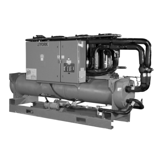
Page 17: Figure 1 - Ycrl Water Cooled Liquid Chiller
COMPRESSOR COMPRESSOR COOLER CONTROL PANEL POWER SECTION FIGURE 1 - YCRL WATER COOLED LIQUID CHILLER JOHNSON CONTROLS... - Page 18 VDC remote air-cooled condenser (available separate- unit alarm contacts. Automatic reset to normal ly from Johnson Controls) or an evaporative condenser. chiller operation after power failure. • Remote water temperature reset via a pulse width...
- Page 19 • Holiday status load and short circuit protection. • Automatic or manual system lead/lag control • Lead system definition • Compressor starts and operating hours (each com- pressor) • Run permissive status • Number of compressors running JOHNSON CONTROLS...
- Page 20 This option will reduce the chiller MCA (minimum circuit ampac- ity) and allow for reduced wire sizing to the unit. This option is not available for applications with Leaving Condenser Water Temperature (LCWT) greater than 105ºF (40.6ºC). (Factory-Mounted) JOHNSON CONTROLS...
-
Page 21: Chiller Options
5/8" (15mm) thickness; one layer of anti-vibrating heavy material thickness of 1/8" (3mm). Both are closed by two sheets of welded PVC, reinforced for temperature and UV resistance. (Factory- Mounted) JOHNSON CONTROLS... -
Page 22: Control / Power Panel Components
FORM 150.27-NM1 SECTION 2 – PRODUCT DESCRIPTION ISSUE DATE: 09/30/2015 CONTROL / POWER PANEL COMPONENTS DISPLAY UNIT SWITCH IPU II/ IO CTB1 BOARD (Flow Switch and Load Limit) LD12922 FIGURE 2 - CONTROL/PANEL COMPONENTS JOHNSON CONTROLS... -
Page 23: Figure 3 - Control Power Panel Components
SECTION 2 – PRODUCT DESCRIPTION ISSUE DATE: 09/30/2015 CONTROL / POWER PANEL COMPONENTS (CONT’D) TRANSFORMER FUSE BLOCK GROUND CONTROL CONTROL CONTROL RELAY TRANSFORMER RELAY CTB2 COMPRESSOR CONTACTORS COMPRESSOR CONTACTORS OPTIONAL SINGLE POINT LD14533 CONNECTIONS FIGURE 3 - CONTROL POWER PANEL COMPONENTS JOHNSON CONTROLS... -
Page 24: Unit Components
LIQUID LINE GLASS SOLENOID STUB-OUT VALVE VALVE SINGLE SPEED SCROLL OPTIONAL ISOLATION VALVE COMPRESSORS COMPRESSOR CRANKCASE HEATER EVAPORATOR WATER OUTLET EVAPORATOR WATER INLET EVAPORATOR VALVE SIGHT LIQUID GLASS LINE SOLENOID FILTER VALVE DRIERS LD14534 FIGURE 4 - UNIT COMPONENTS JOHNSON CONTROLS... -
Page 25: Product Identification Number (Pin)
(PIN 15) STANDARD POWER OPTION (SP SUPPLY TERMINAL BLOCK) SP CIRCUIT BREAKER W/ LOCKABLE HANDLE POWER FIELD POWER (PIN 16 AND 17) SP SUPPLY NF DISCONNECT SWITCH MP SUPPLY W/IND SYS CB AND L. EXT HANDLES SPECIAL QUOTE JOHNSON CONTROLS... - Page 26 SERVICE ISOLATION VALVES (SUCTION) SPECIAL QUOTE SOLENOID VALVES (LIQUID LINE) VALVES VALVES (PIN 32) ELECTRONIC EXPANSION VALVE SPECIAL QUOTE NO OPTION HOT GAS BY-PASS HGBP HOT GAS BY-PASS (1 CIRCUIT) (PIN 33) SPECIAL QUOTE NO OPTION PIN34 PIN 34 SPECIAL QUOTE JOHNSON CONTROLS...
- Page 27 HEAT HEAT RECOVERY (PIN 46) SPECIAL QUOTE NO FLOW SWITCH CONDENDENSER FLOW CONDFLOW SWITCH (PIN 47) SPECIAL QUOTE NO OPTION PIN48 PIN 48 SPECIAL QUOTE NO ACOUSTIC ENCLOSURE ACOUSTICAL ARRGT. ACOUSTIC COMPRESSOR SOUND BLANKET (PIN 49) SPECIAL QUOTE JOHNSON CONTROLS...
- Page 28 NO OPTION PIN 60 PIN 60 SPECIAL QUOTE PLANT OF MFG (PIN 61) MONTERREY CURITIBA, BRAZIL MEXICO, ES MFG LOCATION MONTERY, BE SAN ANTONIO TEXAS YORKWORKS CONFIGURATION VERSION {YW/CV} YORKWORKS VERSION YORKWORKS UPLOAD VERSION {YW/UV} SPECIAL QUOTE SPECIAL QUOTE JOHNSON CONTROLS...
-
Page 29: Refrigerant Flow Diagram - Ycrl (Standard)
The tion and further cooling takes place. The low-pressure high pressure superheat refrigerant enters the remote liquid refrigerant then returns to the cooler. FIELD PROVIDED OPTIONAL RELIEF VALVE BY OTHERS FIGURE 5 - REFRIGERANT FLOW DIAGRAM (STANDARD) JOHNSON CONTROLS... -
Page 30: Refrigerant Flow Diagram - Ycrl (European)
Temperature 38.6 bar 36.3 bar 34.7 bar Service (Stop) Access Valve Refer to Options Pressure Switch Filter Drier (Removable Core) 27.6 bar Refer to Option Options Compressors Evaporator -YLLSV LD12938 FIGURE 6 - REFRIGERANT FLOW DIAGRAM (EUROPEAN) JOHNSON CONTROLS... -
Page 31: Section 3 - Transportation, Handling And Storage
If the unit is to be put into storage, before installation, the following precautions should be observed: Major damage must be reported immediately to your local Johnson Controls representative. • Ensure that all openings, such as water connec- tions, are securely capped. -
Page 32: Lifting Weights
YCRL 60 HZ MODEL - lbs. (kg) 0064HE 0074HE 0084HE 0096HE 0118HE 0126HE 0156HE 0177SE 0198SE 2883 (1308) 3261 (1479) 3439 (1560) 3753 (1702) 3705 (1681) 4587 (2081) 4989 (2263) 4418 (2004) 4773 (2165) FIGURE 7 - CHILLER RIGGING AND LIFTING WEIGHTS JOHNSON CONTROLS... -
Page 33: Section 4 - Installation
The clearances recommended are nomi- ment must be commissioned and serviced nal for the safe operation and mainte- by an authorized Johnson Controls nance of the unit and power and control service mechanic or a qualified service panels. Local health and safety regula- person experienced in chiller installation. -
Page 34: Installation Of Vibration Isolators
150 PSIG (10 barg) working pressure and having 1" N.P.T. connection can be (13 mm) dia. holes in the base of the framework. When obtained from Johnson Controls as an lower transmitted vibration levels are required optional option for the unit. - Page 35 This is especially important if the the heat exchanger nozzles. unit is located in an unheated room where freez- ing could prevail. Water lines subjected to am- bient temperatures below freezing may require heater cables or antifreeze (by others). JOHNSON CONTROLS...
-
Page 36: Water Treatment
Aerated, brackish or salt water is not recommended for must be of sufficient diameter so as not to cause re- use in the water system(s). Johnson Controls recom- sistance to the operation of the valve. For piping size mends that a water treatment specialist is consulted to... -
Page 37: Pipework Arrangement
PRESSURE TAPPING 8” 8-5/8” 3/4 ±1/32” 7/16 ±1/32” 8.416” Flow Switch FLOW SWITCH 6” 6-5/8” 5/8 ±1/32” 3/8 ±1/32” 6.433” Flanged Connection FLANGED CONNECTION 5” 5-9/16” 5/8 ±1/32” 3/8 ±1/32” 5.395 LD06597A FIGURE 10 - PIPEWORK ARRANGEMENTS LEGEND JOHNSON CONTROLS... -
Page 38: Remote Condenser Piping
The refrigerant line velocities have to be sufficiently high to carry oil up suction or hot gas risers at all operating capacities. Johnson Controls assumes no warranty LD13974 responsibility for system operation or FIGURE 12 - EXAMPLE OF TYPICAL EFFECT OF... -
Page 39: Chiller Below Condenser
(refer to Checking Superheat And 3. Saturation temperature ∆t (for other capacities Subcooling on Page 97 in SECTION 6 – COMMIS- and equivalent lengths L SIONING). Actual L Actual Capacity ∆t = Table ∆t X Table L Table Capacity JOHNSON CONTROLS... -
Page 40: Table 2 - Discharge And Liquid Line Capacities In Tons For Refrigerant 410A
Discharge superheat is 105°F. 1.16 0.81 The saturated suction temperature 40°F for liquid line 1.09 0.89 sizing. 1.03 0.96 0.97 1.03 Multiply table capacities by the following factors for condensing temperatures other than 105°F. 0.83 1.16 0.76 1.19 JOHNSON CONTROLS... - Page 41 The saturated condensing and suction conditions are referenced to the dewpoint for R-407C. For other 410A 0.91 0.94 0.97 1.02 saturated suction temperatures with 15°F superheat, use correction factors to the capacity given in the table below. JOHNSON CONTROLS...
-
Page 42: Electrical Connection
Therefore the unit controls must not be modified with- invalidate the warranty. out expressed written consent by Johnson Controls. The use of a simple switch or timer from a remote point No additional controls (relays, etc.) is permitted;... -
Page 43: Ycrl Chiller Charge Capability
Note: Charge for remote condenser and interconnecting piping must be This switch MUST remain in the OFF position until the calculated separately. unit is commissioned by Johnson Controls Authorized CONTROL PANEL WIRING personnel. If the switch is set to the ON position before... -
Page 44: Power Wiring
• Check that the tapping used conforms to the site taken via a common point of isolation (not supply voltage. The two tappings are 342-424V supplied by Johnson Controls). and 360-440V. COMPRESSOR HEATERS Compressor heaters are standard. If power is OFF... -
Page 45: Control Wiring
NO can result in damage to the evaporator LETHAL VOLTAGES are present inside and unit as a result of the chilled liquid the panel AFTER disconnecting power, freezing. PRIOR to working on equipment. FIGURE 13 - CONTROL WIRING JOHNSON CONTROLS... - Page 46 FORM 150.27-NM1 SECTION 4 – INSTALLATION ISSUE DATE: 09/30/2015 THIS PAGE INTENTIONALLY LEFT BLANK JOHNSON CONTROLS...
-
Page 47: Section 5 - Technical Data
1. For leaving brine temperature below 40°F (4.4°C), contact the nearest Johnson Controls Office for application requirements. 2. For leaving water temperature higher than 50°F (10°C), contact the nearest Johnson Controls Office for application guidelines. Excessive flow will cause damage to the Voltage Limitations cooler. -
Page 48: Pressure Drop Charts
YCRL Model Number Evap 0064HE 0074HE, 0084HE, 0118HE, 0096HE 0126HE, 0156HE, 0177SE, 198SE YCRL Evaporator Pressure Drop (SI Units) 1000.0 100.0 10.0 10.0 100.0 Water Flow Rate (l/s) FIGURE 14 - EVAPORATOR WATER PRESSURE DROP CURVES (ENGLISH AND SI) JOHNSON CONTROLS... -
Page 49: Ethylene And Propolyne Glycol Correction Factors
TABLE 9 - RECOMMENDED GLYCOL SOLUTION STRENGTHS PROPYLENE ETHYLENE GLYCOL CONCENTRATION GLYCOL CONCENTRATION % W/W LCHLT °C % W/W LD06934 A = Correction Factor B = Temperature C = Concentration % Through Cooler FIGURE 15 - GLYCOL SOLUTION STRENGTHS JOHNSON CONTROLS... -
Page 50: Physical Data - Standard And High Efficiency - English
REFRIGERANT SIDE PRESSURE (PSIG) DIA. X LENGTH 13” X 8’ 16” X 8’ 16” X 8’ 15” X 10’ 16” X 8’ 17” 10’ 17” 10’ 17” 10’ 17” 10’ (INCHES X FEET) WATER NOZZLE CONNECTION SIZE, (INCHES) JOHNSON CONTROLS... - Page 51 FORM 150.27-NM1 SECTION 5 – TECHNICAL DATA ISSUE DATE: 09/30/2015 THIS PAGE INTENTIONALLY LEFT BLANK JOHNSON CONTROLS...
-
Page 52: Electrical Data - Single Point
#6 AWG - 350 KCM # 4 - 500 KCM 250 - 500 KCM #10 - 300 KCM 0198SE #3/0 - 250 KCM # 4 - 500 KCM 250 - 500 KCM # 4 - 500 KCM * Contact Johnson Controls JOHNSON CONTROLS... - Page 53 32.1 32.1 32.1 69.2 69.2 69.2 69.2 69.2 0177SE 54.5 54.5 54.5 54.5 54.5 49.4 49.4 49.4 49.4 49.4 69.2 69.2 69.2 69.2 69.2 69.2 0198SE 54.5 54.5 54.5 54.5 54.5 54.5 49.4 49.4 49.4 49.4 49.4 49.4 JOHNSON CONTROLS...
-
Page 54: Electrical Data - Dual Point
MIN N/F ELEM ELEM MIN N/F ELEM FUSE ELEM FUSE CIRCUIT CIRCUIT DISC SW FUSE AND FUSE AND DISC SW AND MIN AND MAX AMPS AMPS MIN CB MAX CB 0064HE 0074HE 0084HE 0118HE 0096HE 0126HE 0156HE 0177SE 0198SE JOHNSON CONTROLS... - Page 55 (1) #4 AWG - 300 53.1 290 53.1 290 53.1 290 53.1 290 53.1 290 53.1 290 kCMIL kCMIL (1) #2 - 4/0 AWG 42.5 254.6 42.5 254.6 42.5 254.6 (1) #2 - 4/0 AWG 42.5 254.6 42.5 254.6 42.5 254.6 JOHNSON CONTROLS...
-
Page 56: Single-Point Supply Connection - Terminal Block, Non-Fused Disconnect Switch Or Circuit Breaker
NO can result in damage to the evaporator LETHAL VOLTAGES are present inside and unit as a result of the chilled liquid the panel AFTER disconnecting power, freezing. PRIOR to working on equipment. JOHNSON CONTROLS... -
Page 57: Dual-Point Supply Connection - Terminal Block, Non-Fused Disconnect Switch Or Circuit Breaker
NO can result in damage to the evaporator LETHAL VOLTAGES are present inside and unit as a result of the chilled liquid the panel AFTER disconnecting power, freezing. PRIOR to working on equipment. JOHNSON CONTROLS... -
Page 58: Electrical Data
AFTER disconnecting power, freezing. PRIOR to working on equipment. TABLE 11 - VOLTAGE RANGE (LIMITATIONS) VOLTAGE RANGE VOLTAGE CODE UNIT POWER MIN. MAX. 200-3-60 230-3-60 380/415-3-60 460-3-60 380/415-3-50 575-3-60 JOHNSON CONTROLS... -
Page 59: Electrical Notes
FULL LOAD AMPS HERTZ MAXIMUM MINIMUM CIRCUIT AMPACITY MINIMUM MIN NF MINIMUM NON FUSED RATED LOAD AMPS S.P. WIRE SINGLE POINT WIRING UNIT MTD SERV SW UNIT MOUNTED SERVICE (NON-FUSED DISCONNECT SWITCH) LOCKED ROTOR AMPS ECWT ENTERING CONDENSER WATER TEMPERATURE JOHNSON CONTROLS... -
Page 60: Table 12 - Ground Lug Sizing
(2) # 4 - 3/0 AWG Notes: 1. Start in correct power option table (breaker, terminal block) 2. Match engineering guide value for Amperage 3. Match engineering guide value for wire range 4. Note corresponding ground wire range JOHNSON CONTROLS... - Page 61 FORM 150.27-NM1 SECTION 5 – TECHNICAL DATA ISSUE DATE: 09/30/2015 THIS PAGE INTENTIONALLY LEFT BLANK JOHNSON CONTROLS...
-
Page 62: Elementary Wiring Diagram
FORM 150.27-NM1 SECTION 5 – TECHNICAL DATA ISSUE DATE: 09/30/2015 WIRING DIAGRAMS ELEMENTARY WIRING DIAGRAM YCRL0064, 0074, 0084, and 0118 FIGURE 18 - STANDARD POWER, SINGLE POINT AND MULTIPLE POINT CONTROL PANEL WIRING, 4 COMPRESSOR UNIT JOHNSON CONTROLS... - Page 63 FORM 150.27-NM1 SECTION 5 – TECHNICAL DATA ISSUE DATE: 09/30/2015 FIGURE 18 - STANDARD POWER, SINGLE POINT AND MULTIPLE POINT CONTROL PANEL WIRING, 4 COMPRESSOR UNIT (CONT'D) JOHNSON CONTROLS...
-
Page 64: Figure 19 - Standard Power, Single Point And Multiple Point Control Panel Wiring, 6 Compressor Unit
FORM 150.27-NM1 SECTION 5 – TECHNICAL DATA ISSUE DATE: 09/30/2015 ELEMENTARY WIRING DIAGRAM YCRL0096, 0126, 0156, 0177 and 0198 FIGURE 19 - STANDARD POWER, SINGLE POINT AND MULTIPLE POINT CONTROL PANEL WIRING, 6 COMPRESSOR UNIT JOHNSON CONTROLS... - Page 65 FORM 150.27-NM1 SECTION 5 – TECHNICAL DATA ISSUE DATE: 09/30/2015 FIGURE 19 - STANDARD POWER, SINGLE POINT AND MULTIPLE POINT CONTROL PANEL WIRING, 6 COMPRESSOR UNIT JOHNSON CONTROLS...
-
Page 66: Figure 20 - Standard Power And Single Point Power Circuit, 4 Compressor Unit
FORM 150.27-NM1 SECTION 5 – TECHNICAL DATA ISSUE DATE: 09/30/2015 ELEMENTARY WIRING DIAGRAM YCRL0064, 0074, 0084, and 0118 LD 12925 FIGURE 20 - STANDARD POWER AND SINGLE POINT POWER CIRCUIT, 4 COMPRESSOR UNIT JOHNSON CONTROLS... -
Page 67: Figure 21 - Multiple Point Power Circuit, 4 Compressor Unit
FORM 150.27-NM1 SECTION 5 – TECHNICAL DATA ISSUE DATE: 09/30/2015 ELEMENTARY WIRING DIAGRAM YCRL0064, 0074, 0084, and 0118 LD 13998 FIGURE 21 - MULTIPLE POINT POWER CIRCUIT, 4 COMPRESSOR UNIT JOHNSON CONTROLS... -
Page 68: Figure 22 - Standard Power And Single Point Power Circuit, 6 Compressor Unit
FORM 150.27-NM1 SECTION 5 – TECHNICAL DATA ISSUE DATE: 09/30/2015 ELEMENTARY WIRING DIAGRAM YCRL0096, 0126, 0156, 0177 and 0198 FIGURE 22 - STANDARD POWER AND SINGLE POINT POWER CIRCUIT, 6 COMPRESSOR UNIT JOHNSON CONTROLS... -
Page 69: Figure 23 - Multiple Point Power Circuit, 6 Compressor Unit
FORM 150.27-NM1 SECTION 5 – TECHNICAL DATA ISSUE DATE: 09/30/2015 ELEMENTARY WIRING DIAGRAM (CONT'D) YCRL0096, 0126, 0156, 0177 and 0198 LD14000 FIGURE 23 - MULTIPLE POINT POWER CIRCUIT, 6 COMPRESSOR UNIT JOHNSON CONTROLS... -
Page 70: Figure 24 - Standard Power And Single Point Connection Wiring Diagram, 4 Compressor Unit
FORM 150.27-NM1 SECTION 5 – TECHNICAL DATA ISSUE DATE: 09/30/2015 CONNECTION WIRING DIAGRAM YCRL0064, 0074, 0084, and 0118 LD12926 FIGURE 24 - STANDARD POWER AND SINGLE POINT CONNECTION WIRING DIAGRAM, 4 COMPRESSOR UNIT JOHNSON CONTROLS... - Page 71 FORM 150.27-NM1 SECTION 5 – TECHNICAL DATA ISSUE DATE: 09/30/2015 LD12927 FIGURE 24 - STANDARD POWER AND SINGLE POINT CONNECTION WIRING DIAGRAM, 4 COMPRESSOR UNIT JOHNSON CONTROLS...
-
Page 72: Figure 25 - Multiple Point Power Connection Wiring Diagram, 4 Compressor Unit
FORM 150.27-NM1 SECTION 5 – TECHNICAL DATA ISSUE DATE: 09/30/2015 CONNECTION WIRING DIAGRAM YCRL0064, 0074, 0084, and 0118 FIGURE 25 - MULTIPLE POINT POWER CONNECTION WIRING DIAGRAM, 4 COMPRESSOR UNIT JOHNSON CONTROLS... - Page 73 FORM 150.27-NM1 SECTION 5 – TECHNICAL DATA ISSUE DATE: 09/30/2015 LD13999 FIGURE 25 - MULTIPLE POINT POWER CONNECTION WIRING DIAGRAM, 4 COMPRESSOR UNIT (CONT'D) JOHNSON CONTROLS...
-
Page 74: Figure 26 - Standard Power And Single Point Connection Wiring Diagram, 6 Compressor Unit
FORM 150.27-NM1 SECTION 5 – TECHNICAL DATA ISSUE DATE: 09/30/2015 CONNECTION WIRING DIAGRAM YCRL0096, 0126, 0156, 0177 and 0198 FIGURE 26 - STANDARD POWER AND SINGLE POINT CONNECTION WIRING DIAGRAM, 6 COMPRESSOR UNIT JOHNSON CONTROLS... - Page 75 FORM 150.27-NM1 SECTION 5 – TECHNICAL DATA ISSUE DATE: 09/30/2015 FIGURE 26 - STANDARD POWER AND SINGLE POINT CONNECTION WIRING DIAGRAM, 6 COMPRESSOR UNIT (CONT'D) JOHNSON CONTROLS...
-
Page 76: Figure 27 - Multiple Point Connection Wiring Diagram, 6 Compressor Unit
FORM 150.27-NM1 SECTION 5 – TECHNICAL DATA ISSUE DATE: 09/30/2015 CONNECTION WIRING DIAGRAM YCRL0096, 0126, 0156, 0177 and 0198 FIGURE 27 - MULTIPLE POINT CONNECTION WIRING DIAGRAM, 6 COMPRESSOR UNIT JOHNSON CONTROLS... - Page 77 FORM 150.27-NM1 SECTION 5 – TECHNICAL DATA ISSUE DATE: 09/30/2015 LD14001 FIGURE 27 - MULTIPLE POINT CONNECTION WIRING DIAGRAM, 6 COMPRESSOR UNIT (CONT'D) JOHNSON CONTROLS...
-
Page 78: Figure 28 - Standard Power, Single Point And Multiple Point Elementary Wiring Diagram Details
(class 2) connections. See Note 2. Terminal block for YORK and customer connections. Wiring and components by YORK. Optional equipment. Wiring and/or components by others. FIGURE 28 - STANDARD POWER, SINGLE POINT AND MULTIPLE POINT ELEMENTARY WIRING DIAGRAM DETAILS, 4 COMPRESSOR JOHNSON CONTROLS... - Page 79 FORM 150.27-NM1 SECTION 5 – TECHNICAL DATA ISSUE DATE: 09/30/2015 ELEMENTARY WIRING DIAGRAM DETAILS (CONT’D) LD12929 FIGURE 28 - STANDARD POWER, SINGLE POINT AND MULTIPLE POINT ELEMENTARY WIRING DIAGRAM DETAILS, 4 COMPRESSOR (CONT'D) JOHNSON CONTROLS...
-
Page 80: Figure 29 - Standard Power, Single Point And Multiple Point Elementary Wiring Diagram Details
Note 2. Terminal block for YORK and customer connections. Wiring and components by YORK. Optional equipment. Wiring and/or components by others. LD12935 FIGURE 29 - STANDARD POWER, SINGLE POINT AND MULTIPLE POINT ELEMENTARY WIRING DIAGRAM DETAILS, 6 COMPRESSOR JOHNSON CONTROLS... - Page 81 FORM 150.27-NM1 SECTION 5 – TECHNICAL DATA ISSUE DATE: 09/30/2015 ELEMENTARY WIRING DIAGRAM DETAILS (CONT’D) FIGURE 29 - STANDARD POWER, SINGLE POINT AND MULTIPLE POINT ELEMENTARY WIRING DIAGRAM DETAILS, 6 COMPRESSOR (CONT'D) JOHNSON CONTROLS...
-
Page 82: Figure 30 - Eev Controller Wiring
FORM 150.27-NM1 SECTION 5 – TECHNICAL DATA ISSUE DATE: 09/30/2015 ELEMENTARY WIRING DIAGRAM DETAILS (CONT’D) FIGURE 30 - EEV CONTROLLER WIRING JOHNSON CONTROLS... -
Page 83: Unit Dimensions - English - Four Compressor
34.4 34.8 12.3 12.8 12.8 12.8 GG-1 39.5 39.5 39.5 12.3 12.3 12.3 12.3 GG-2 39.5 39.5 39.5 12.3 12.3 12.3 12.3 18.3 14.7 14.7 14.9 H* - for 200/230 volt units, which require a larger electrical enclosure JOHNSON CONTROLS... -
Page 84: Unit Dimensions - English - Six Compressor
53.7 53.7 GG-1 12.3 12.3 12.3 12.3 12.3 57.9 57.7 53.7 53.7 53.7 GG-2 12.3 12.3 12.3 12.3 12.3 14.7 14.9 14.9 14.9 14.9 102.0 102.0 H* - for 200/230 volt units, which require a larger electrical enclosure JOHNSON CONTROLS... -
Page 85: Isolator Selection Data
4587 5037 1008 1386 PINK/GRAY 0126HE GRAY/RED C2P-1D-2400 RD-4 BRICK 4989 5439 1084 1609 PINK/GRAY 0156HE GRAY CP-1D-1785N RD-4 BRICK 4418 4773 1380 1054 PINK 0177SE GRAY/RED C2P-1D-1800 RD-4 BRICK 4868 5223 1522 1089 PINK/GRAY 0198SE DK. GREEN JOHNSON CONTROLS... -
Page 86: Isolator Information
GRAY/RED RATED RATED MODEL NUMBER CAPACITY DEFLECTION COLOR CODE (LBS.) (IN) CP2-1D-1020 1020 1.02 BLACK CP2-1D-1350 1350 1.32 DK. PURPLE CP2-1D-1800 1800 1.02 DK. GREEN CP2-1D-2400 2400 GRAY CP2-1D-2720 2720 0.77 WHITE CP2-1D-3570N 3570 0.88 GRAY / RED JOHNSON CONTROLS... -
Page 87: One Inch Deflection Spring Isolators Installation Instructions
(See drawing below). elevation (1/4-inch maximum difference can be 9. Fine adjust isolators to level equipment. tolerated). 10. Installation is complete. 4. Bolt or anchor all isolators to supporting structure utilizing base slotted holes (“C”). LD13790 JOHNSON CONTROLS... - Page 88 RATED RATED DURO DURO MODEL NUMBER CAPACITY DEFLECTION MODEL NUMBER CAPACITY DEFLECTION (± 5) (± 5) [LBS] [IN] [LBS] [IN] RD2-Light Blue-WR RD4-Brown-WR 1500 RD2-Brown-WR RD4-Brick Red-WR 2250 RD2-Brick Red-WR RD4-Lime-WR 3000 RD 2-Lime-WR RD4-Charcoal-WR 4000 RD2 Charcoal-WR JOHNSON CONTROLS...
-
Page 89: Installation Of Duralene Vibration Isolators
5. REMOVE TOP BOLT AND TOP WASHER. PLACE EQUIPMENT ON TOP OF ISOLATORS SO THAT MOUNTING HOLES IN EQUIPMENT OR BASE LINE UP WITH THREADED HOLE ("C"). 6. REINSTALL TOP BOLT AND WASHER AND TIGHTEN DOWN. 7. INSTALLATION IS COMPLETE. TOP BOLT ("B") TOP WASHER ("C") ("B") ("A") SECTION D-D LD13762 JOHNSON CONTROLS... - Page 90 1450 1.81 2450 Y2RSI-2D-1690 1690 1.69 1140 2892 PINK PINK/ Y2RSI-2D-2000N 2000 1.69 1318 3342 BLACK PINK/ Y2RSI-2D-2640N 2640 1.54 1854 4283 GRAY PINK/GRAY/ Y2RSI-2D-2870N 3080 1.54 2004 4629 ORANGE PINK/GRAY/ Y2RSI-2D-3280N 3740 1.75 2134 4930 DK BROWN JOHNSON CONTROLS...
-
Page 91: Seismic Isolator Installation And Adjustment
THE LIMIT STOP NUTS MUST BE KEPT AT THIS GAP TO ENSURE UNIFORM BOLT LOADING DURING UPLIFT (AS THE CASE WHEN EQUIPMENT IS DRAINED). 13. INSTALLATION IS COMPLETE. ("G") ("E") ("A") ("A") ("E") GROMMET 1/4 - 3/8 GAP EQUIPMENT ("F") WASHER ("E") ("F") ("C") ("C") ("B") LD13763A JOHNSON CONTROLS... - Page 92 FORM 150.27-NM1 SECTION 5 – TECHNICAL DATA ISSUE DATE: 09/30/2015 THIS PAGE INTENTIONALLY LEFT BLANK JOHNSON CONTROLS...
-
Page 93: Section 6 - Commissioning
Compressor Oil Commissioning of this unit should only To add oil to a circuit – connect a YORK hand oil pump be carried out by Johnson Controls Au- (Part No. 470-10654-000) to the 1/4" oil charging con- thorized personnel. nection on the compressors with a length of clean hose or copper line, but do not tighten the flare nut. -
Page 94: Grounding
This sensor also provides the compressor and the oil. If the ambient temperature some freeze protection and must always be fully in- is below 86 °F (30 °C), allow 24 hours. serted in the water outlet sensor well. JOHNSON CONTROLS... -
Page 95: Equipment Pre Start-Up And Start-Up Checklist
Table 13. (See Setpoints Keys on Page 116 and Unit Keys on Page 123 for program- 7. Check the control panel to ensure it is free of … … ming instruction) foreign material (wires, metal chips, etc.). JOHNSON CONTROLS... -
Page 96: Table 13 - Setpoints Entry List
Af- * Not on All Models ter verifying proper compressor rotation, turn ** Viewable Only the Unit Switch to OFF. Excessive flow may cause catastrophic damage to the heat exchanger (evapora- tor). JOHNSON CONTROLS... -
Page 97: Checking Superheat And Subcooling
10 °F with only a single com- sors cycle to control water temperature to setpoint, the pressor running on a circuit. chiller is ready to be placed into operation. JOHNSON CONTROLS... -
Page 98: Unit Operating Sequence
180 system with the shortest average run-time of the seconds, whichever comes first. compressors will be assigned as the “lead” sys- tem. A new lead/lag assignment is made whenever all systems shut down. JOHNSON CONTROLS... -
Page 99: Section 7 - Unit Controls
The keypad A Master ON/OFF switch is available to activate orde- and display are connected to the I/O board. activate the unit. JOHNSON CONTROLS... -
Page 100: Unit Switch
The total number of compressors is programmable un- The display has a lighted background for night viewing der the PROGRAM key. Chillers can have 4 or 6 com- and for viewing in direct sunlight. pressors. JOHNSON CONTROLS... -
Page 101: Status Key
S W I T C H O F F SYS SWITCH OFF tells that the system switch under OPTIONS is turned OFF. The system will not be al- lowed to run until the switch is turned back on. JOHNSON CONTROLS... - Page 102 STATUS messages when in the MANUAL installed in the system. OVERRIDE mode. MANUAL OVERRIDE is to only be used in emergencies or for servicing. MANUAL OVER- RIDE mode automatically disables itself after 30 minutes. JOHNSON CONTROLS...
-
Page 103: Fault Safety Status Messages
PSIG below the cutout. Discharge transducers must be CR contacts to open causing 0VDC to be read on the installed for this function to operate. inputs to the microboard. The fault condition is cleared when a 30VDC signal is restored to the input. JOHNSON CONTROLS... -
Page 104: Unit Safeties
Re- age for 5 seconds, the system will shutdown. start is allowed after the unit is fully powered again and the anti-recycle timers have finished counting down. JOHNSON CONTROLS... -
Page 105: Unit Warning
P R O G / S E T P / O P T N chiller. The Low Battery Warning can only occur at unit pow- er-up. On micro panel power-up, the RTC battery is checked. If a low battery is found, all programmed setpoints, program values, options, time, schedule, and JOHNSON CONTROLS... -
Page 106: Status Key Messages
High Motor Current System X AC Timer System X Disch Limiting System X Suction Limiting System X Percentage Load Limiting Manual Overide Status System X Pumping Down (on shutdown) LD11297A FIGURE 31 - STATUS KEY MESSAGES QUICK REFERENCE LIST JOHNSON CONTROLS... -
Page 107: Display/Print Keys
A I R T E M P 8 7 . 5 ° F This display shows the ambient air temperature. The minimum limit on the display is 0.4 °F (-17.6 °C). The maximum display is 131.2 °F (55.1 °C). JOHNSON CONTROLS... - Page 108 Whether the systems loads or unloads is determined by how far the actual liquid temperature is from setpoint. A detailed description of unit loading and unloading is covered under the topic of Capacity Control. JOHNSON CONTROLS...
- Page 109 This message does not ap- tact closure. ply to a YCRL chiller and is displayed as a result of • PWM TEMP – EMS temperature reset the use of software common to YCA, YCRL and YCW chillers. JOHNSON CONTROLS...
-
Page 110: Oper Data Quick Reference List
*Sys X LLSV and HGSV Status *System X Condenser Fan Stage (This message is not applicable to a YCRL chiller.) Current Feedback One Per System LD12585B * Block of information repeats for each system FIGURE 32 - OPERATION DATA JOHNSON CONTROLS... -
Page 111: Print Key
DEFROST TERMINATION TIME 3MIN THU START=00:00AM STOP=00:00AM BIVALENT HEAT DELAY TIME 30 MIN FRI START=00:00AM STOP=00:00AM REMOTE UNIT ID PROGRAMMED SAT START=00:00AM STOP=00:00AM YORK HYDRO KIT PUMPS 1 (410a) HOL START=00:00AM STOP=00:00AM PUMP TOTAL RUN HOURS XXXXX (410a) JOHNSON CONTROLS... -
Page 112: History Printout
L O C A L / R E M O T E M O D E SYS 1 HIGH DSCH PRESS SHUTDOWN X X X X X X X X X SYS 2 NO FAULTS Displays Local or Remote control selection. JOHNSON CONTROLS... - Page 113 L I Q U I D T E M P C U T O U T X X X . X ° F Displays which system is in the lead at the time of the fault. Displays the Leaving Liquid Temp. Cutout programmed. JOHNSON CONTROLS...
-
Page 114: Software Version
S A T S U C T X X X . X ° F I / O C. M X X. 1 8. Y Y Displays the System Suction Temp and Saturated Suc- tion Temp when an EEV is installed. JOHNSON CONTROLS... -
Page 115: Entry Keys
↓ (DOWN) arrow keys. arrow key, and ↓ (DOWN) arrow, and ENTER/ADV The ↑ (UP) arrow key, and ↓ (DOWN) arrow key are keys are covered in detail under the SETPOINTS, and also used for programming the control panel such as UNIT keys. changing numerical or text values when programming JOHNSON CONTROLS... -
Page 116: Setpoints Keys
.5 °F increments, to the desired RANGE setpoint. liquid) will be displayed for a few seconds, and the set- After adjusting the setpoint, the ENTER/ADV key point display entry screen will appear. must be pressed to enter the data into memory. JOHNSON CONTROLS... -
Page 117: Return Chilled Liquid Control
M O N S T A R T 0 0 : 0 0 remote PWM signal. These setpoints would only be S T O P 0 0 : 0 0 valid if the unit was operating in the REMOTE mode. JOHNSON CONTROLS... -
Page 118: Table 14 - Cooling Setpoints, Programmable Limits And Defaults
* When using glycol, Leaving Chilled Liquid Setpoint should not be set below 20 °F (-6.7 °C). ** Do not exceed 55 °F (12.8 °C) setpoint before contacting the nearest Johnson Controls Office for application guidelines. The line under the 0 is the cursor. If the value is wrong, After SUN (Sunday) schedule appears on the display it may be changed by using the ↑ (UP) and ↓ (DOWN) -
Page 119: Program Key
D I F F E R E N T I A L O F F explained under the System Safeties topic. P R E S S U R E X X X P S I G Does not apply to YCRL. JOHNSON CONTROLS... -
Page 120: System Trip Volts
For example, if fan and compressor RLA’s total 100A: 5V x 100A 625VA 1.25 = = 2.8V 225A 225A The programmed value will be 2.8V. A similar calcula- tion and programming will be necessary for the other system in a 2-system chiller. JOHNSON CONTROLS... -
Page 121: Unit Trip Volts
Fan Differential Off Pressure — (Not Applicable To A Ycrl) Single System Total Number Of Compressors Dual System Number Of Fans Per System Unit/System Trip Volts Current Feedback 0.5 Volts 4.5 Volts 2.5 Volts Remote Unit Id — JOHNSON CONTROLS... -
Page 122: Figure 33 - Setpoints Quick Reference List
Fan Differential Off-Pressure (Not applicable to a YCRL) Total Numbers Compressors Number of Fans Per System (Not applicable to a YCRL) SYS / Unit Trip Volts Option Remote Unit ID LD07404c FIGURE 33 - SETPOINTS QUICK REFERENCE LIST JOHNSON CONTROLS... -
Page 123: Unit Keys
S W I T C H G L Y C O L This allows both systems to run The chilled liquid is glycol. The Cooling Setpoint can be programmed from 10 °F to 70 °F (-12.2 °C to 21.1 °C). JOHNSON CONTROLS... -
Page 124: Option 4 - Ambient Control Type
C O N T R O L L E A V I N G L I Q U I D D I S C H A R G E P R E S S U R E Does not apply to a YCRL chiller. JOHNSON CONTROLS... -
Page 125: Option 10 - Manual Override Mode
This mode should be selected when an optional 2ACE module is installed to allow individual current moni- toring of each system. SYS 1 input is to J7 of the I/O. SYS 2 input is to J8 of the I/O. JOHNSON CONTROLS... -
Page 126: Option 15 - Refrigerant Type
A Flash Card is used to input the operating program into the chiller IPU. A Flash Card is used instead of an EPROM. Normally, a Flash Card update is not required and the message above will be displayed. JOHNSON CONTROLS... -
Page 127: Option 19 - Pump Control
Press the ↑ (UP) or ↓ (DOWN) arrow keys until the desired hour, minute, meridian; day, month, and year are dis- played. Pressing the ENTER/ADV Key will save the valve and move the cursor on to the next programma- ble variable. JOHNSON CONTROLS... -
Page 128: Figure 34 - Unit Keys Options Programming Quick Reference List
Power Failure Restart Soft Start Option Unit Type (”Chiller” MUST be Selected Via No Jumper Installed (Viewable Only) Refrigerant Type R-410A (Programmed under Service Mode) Viewable Only) LD07405d FIGURE 34 - UNIT KEYS OPTIONS PROGRAMMING QUICK REFERENCE LIST JOHNSON CONTROLS... -
Page 129: Section 8 - Unit Operation
Setpoint = 46.0 ºF (7.8 ºC) Range = +/-2 ºF (1.1 ºC) the affected system drops to 85% of the unload pres- LD14404 sure and 10 minutes have elapsed. FIGURE 35 - LEAVING WATER TEMPERATURE CONTROL EXAMPLE This control is only applicable if optional discharge pressure transducers are installed. JOHNSON CONTROLS... -
Page 130: Leaving Chilled Liquid Control Override To Reduce Cycling
50 lead system first or unloading the lag system first. °F, the setpoint high limit will be set to 50 °F, and the difference will be added to the setpoint low limit. JOHNSON CONTROLS... -
Page 131: Return Chilled Liquid Control
1. Step 1 is Hot Gas Bypass and is skipped when loading occurs. Hot Gas Bypass operation is inhibited during Pumpdown. 2. Step 3 is skipped when loading occurs. 3. Step 4 is skipped when unloading occurs. * STEP can be viewed using the OPER DATA key and scrolling to COOLING DEMAND. JOHNSON CONTROLS... -
Page 132: Return Chilled Liquid System Lead/Lag And Compressor Sequencing
Manual Lead/Lag selects specifically the sequence timer has timed out. If the lead system has run for less which the microprocessor starts the systems. than 5 minutes, 3 times in a row, the anti-recycle timer will be extended to 10 minutes. JOHNSON CONTROLS... -
Page 133: Anti-Coincidence Timer
CTB2 – terminals 25 to 26 for system 1 and allowed to run until the suction pressure falls below the cutout, or for 180 seconds, whichever comes first. CTB2 – terminals 27 to 28 for system 2. JOHNSON CONTROLS... -
Page 134: Alarm Status
*Max Reset Value = 20 °F (11.11 °C) Local Chilled Liquid Setpoint = 45°F (7.22°C). Input Signal = 6VDC *Max Reset Value = 10°F (5.56°C) Contact Closure Time = 6 Seconds. (English) (6 sec. - 1) (10°F/10) = 5°F Reset JOHNSON CONTROLS... -
Page 135: Vdc Pressure Setting Guidelines
VDC PRESSURE SETTING GUIDELINES °Reset = 6VDC x 20 °F = 12 °F Reset When a Johnson Controls remote condenser type VDC is used with a YCRL chiller, the VDC must be ordered New Setpoint = 45 °F + 12 °F = 57 °F and installed with the “Head Pressure Control –... - Page 136 FORM 150.27-NM1 SECTION 8 – UNIT OPERATION ISSUE DATE: 09/30/2015 THIS PAGE INTENTIONALLY LEFT BLANK JOHNSON CONTROLS...
-
Page 137: Section 9 - Service And Troubleshooting
EVAP PUMP TOTAL RUN HOURS put ON/OFF or modify the value. SYS 1 HOURS SYS 2 HOURS SYS 1 STARTS SYS 2 STARTS Each display will also show the output connection on the microboard for the respective output status shown. For example: JOHNSON CONTROLS... -
Page 138: Service Mode - Chiller Configuration
↑ (UP) and ↓ (DOWN) arrow keys, but under normal circumstances would not be required or advised. After the last start display, the microprocessor will display the first pro- grammable value under the PROGRAM key. JOHNSON CONTROLS... -
Page 139: Control Inputs/Outputs
(Sys 2 Motor Protector/High Pressure Cutout) SYS 2 Low Pressure Switch SYS 2 Discharge Pressure Transducer J9-11 (Optional) J7-12 Unit/SYS 1 Voltage J9-12 SYS 2 Voltage J11-11 Remote Temperature Reset TABLE 23 - I/O ANALOG OUTPUTS Not Applicable JOHNSON CONTROLS... -
Page 140: Microboard Layout
FORM 150.27-NM1 SECTION 9 – SERVICE AND TROUBLESHOOTING ISSUE DATE: 09/30/2015 MICROBOARD LAYOUT I/O BOARD BOARD TB10 LD12721 FIGURE 37 - MICROBOARD LAYOUT JOHNSON CONTROLS... -
Page 141: Checking Inputs And Outputs
J6-7 = VDC input signal to the microboard. See Table 24 on page 141 for voltage readings that cor- 3.11 respond to specific liquid temperatures. 3.17 J6-1 = drain (shield connection = 0VDC) Return 3.23 3.29 3.34 3.39 3.45 3.54 JOHNSON CONTROLS... -
Page 142: Analog Inputs - Pressure
Red Wire = 5V, Black wire = 0V, White/Green Wire = signal TEST POINTS: Suction Pressure: System 1: ........Microboard J7-10 to J7-9 System 2: ........Microboard J9-10 to J9-9 Discharge Pressure: System 1: ........Microboard J7-11 to J7-7 System 2: ........Microboard J9-11 to J9-7 JOHNSON CONTROLS... -
Page 143: Digital Outputs
TB10 SYS 2 TB10-4 COMPR 2 (5) SYS 2 TB10-5 COMPR 3 (6) SYS 2 TB10-7 HGSV TB10-8 TB10 TB10-9 TB10-10 TB8-6 EVAP PUMP TB8-7 HEAT EXCH TB8-2 HEATER LD12722A FIGURE 38 - I/O BOARD RELAY CONTACT ARCHITECTURE JOHNSON CONTROLS... -
Page 144: Optional Printer Installation
The part number for the printer that is packaged spe- Obtaining a Printout cifically for Johnson Controls is P/N 950915576. The A printout is obtained by pressing the PRINT key on cable to connect the printer can either be locally as-... -
Page 145: Troubleshooting
5. Defective IPU II and I/O Board or 5. Replace IPU II and I/O Board or the Display the Display Board. Board. Contact Johnson Controls Service before replacing circuit boards. 1. No chilled liquid flow. 1. Check chilled liquid flow. - Page 146 3. Contactor/Overload failure. 3. Replace defective part. 4. Compressor failure. 4. Diagnose cause of failure and replace. 1. Fouled evaporator surface. 1. Contact the local Johnson Controls service Low suction pressure will be representative. observed. 2. Improper flow through the 2.
-
Page 147: Section 10 - Maintenance
02630 IPU II board that maintains the date/time and may or may not be furnished by Johnson Controls. stores customer programmed setpoints. The Real Time System components should be maintained according to Clock is a 128K bram, P/N 031-02565-000. -
Page 148: Bacnet, Modbus And Yorktalk 2 Communications
XXXXX ADDRESS P2 STOP BITS P1 BAUD RATE XXXXX P2 HW SELECT BIT P1 PARITY XXXXX XXXXX REAL TIME ERROR P1 STOP BITS RESET 1 = YES, 0 = NO 0 Note: See Table 29 for error descriptions JOHNSON CONTROLS... -
Page 149: Figure 40 - Micro Panel Connections
P1, P2 Parity None Ignore None None, Even, Odd, Ignore Selectable P1 Protocol BACNET BACNET BACNET, API Selectable P2 Protocol Terminal Modbus Client Terminal, Modbus Io, Modbus Server, API, Modbus Client Selectable P1, P2 Stop Bits Reset Real Time Error JOHNSON CONTROLS... -
Page 150: Table 28 - Values Required For Bas Communication
Get Packet Failed scription of each. Get Type Failed Invalid Unit Conversion Invalid Hardware Selection Real Time Fault Spanish Text Too Long Thread Exited Thread Failed Thread Stalled IO Board Reset Bram Invalid Bacnet Setup Failed JOHNSON CONTROLS... -
Page 151: Bacnet And Modbus Communications
BACnet and Modbus registers. PPM = Part per Million The latest data map information is listed kJ/kg = Kilojoules per Kilogram on the Johnson Controls Equipment In- 4. Water Cooled Scroll units use the same firmware tegration website. as Air Cooled Scroll units, ignoring Fan Control. JOHNSON CONTROLS... -
Page 152: Table 30 - Bacnet And Modbus Communications Data Map
FORM 150.27-NM1 SECTION 10 – MAINTENANCE ISSUE DATE: 09/30/2015 TABLE 30 - BACNET AND MODBUS COMMUNICATIONS DATA MAP JOHNSON CONTROLS... - Page 153 FORM 150.27-NM1 SECTION 10 – MAINTENANCE ISSUE DATE: 09/30/2015 TABLE 30 - BACNET AND MODBUS COMMUNICATIONS DATA MAP (CONT’D) JOHNSON CONTROLS...
- Page 154 FORM 150.27-NM1 SECTION 10 – MAINTENANCE ISSUE DATE: 09/30/2015 TABLE 30 - BACNET AND MODBUS COMMUNICATIONS DATA MAP (CONT’D) JOHNSON CONTROLS...
-
Page 155: Yorktalk 2 Communications
Table 31 on page 156 The latest point map information is listed “Yorktalk 2 Communications Data Map” lists the con- on the Johnson Controls Equipment In- trol parameters. These values are found under feature tegration website. -
Page 156: Table 31 - Yorktalk 2 Communications Data Map
FORM 150.27-NM1 SECTION 10 – MAINTENANCE ISSUE DATE: 09/30/2015 TABLE 31 - YORKTALK 2 COMMUNICATIONS DATA MAP JOHNSON CONTROLS... - Page 157 FORM 150.27-NM1 SECTION 10 – MAINTENANCE ISSUE DATE: 09/30/2015 TABLE 31 - YORKTALK 2 COMMUNICATIONS DATA MAP (CONT’D) JOHNSON CONTROLS...
- Page 158 FORM 150.27-NM1 SECTION 10 – MAINTENANCE ISSUE DATE: 09/30/2015 TABLE 31 - YORKTALK 2 COMMUNICATIONS DATA MAP (CONT’D) JOHNSON CONTROLS...
-
Page 159: Temperature Conversion Chart
186.8 22.07 16.5 239.3 100.0 190.4 22.76 246.5 102.2 23.45 17.5 253.8 104.4 197.6 24.14 106.7 201.2 24.83 18.5 268.3 108.9 204.8 25.52 275.5 111.1 208.4 26.21 19.5 282.8 113.3 26.9 115.6 215.6 27.59 20.5 297.3 117.8 219.2 JOHNSON CONTROLS... -
Page 160: R410-A Pressure Temperature Chart
FORM 150.27-NM1 SECTION 10 – MAINTENANCE ISSUE DATE: 09/30/2015 R410-A PRESSURE TEMPERATURE CHART TEMP ˚F TEMP ˚F PSIG PSIG JOHNSON CONTROLS... -
Page 161: Temperature
(°C), subtract 32° and multiply by 5/9 or 0.5556. Example: (45.0°F - 32°) x 0.5556 = 7.22°C To convert a temperature range (i.e., a range of 10°F) from Fahrenheit to Celsius, multiply by 5/9 or 0.5556. Example: 10.0°F range x 0.5556 = 5.6 °C range JOHNSON CONTROLS... - Page 162 P.O. Box 1592, York, Pennsylvania USA 17405-1592 800-861-1001 Subject to change without notice. Printed in USA Copyright © by Johnson Controls 2015 www.johnsoncontrols.com ALL RIGHTS RESERVED Form 150.27-NM1 (915) Issue Date: September 30, 2015 Supersedes: 150.27-NM1 (511)
Need help?
Do you have a question about the York YCRL0064 and is the answer not in the manual?
Questions and answers