Sungrow SH5K-20 User Manual
1-phase hybrid inverter
Hide thumbs
Also See for SH5K-20:
- User manual (99 pages) ,
- Commissioning (10 pages) ,
- Quick user manual (69 pages)

Related Manuals for Sungrow SH5K-20


Summary of Contents for Sungrow SH5K-20
- Page 1 1-Phase Hybrid Inverter User Manual SH5K-20 WWW.SUNGROWPOWER.COM SH5K-20-UEN-Ver19-202007...
- Page 3 Software Licenses It is prohibited to use data contained in firmware or software developed by SUNGROW, in part or in full, for commercial purposes by any means. It is prohibited to perform reverse engineering, cracking, or any other operations that compromise the original program design of the software developed by SUNGROW.
-
Page 4: About This Manual
Documents must be stored carefully and be available at all times. All rights to the content of this manual are owned by Sungrow Power Supply Co., Ltd. (hereinafter “SUNGROW”). No part of this document can be modified, distributed, reproduced or published in any form or by any means without prior written permission from SUNGROW. - Page 5 Symbol Explanation Indicates a hazard with a low level of risk that, if not avoided, could result in minor or moderate injury. Indicates a situation that, if not avoided, could result in equipment or property damage. Indicates additional information, emphasized contents or tips that may be helpful, e.g.
-
Page 6: Table Of Contents
Contents About This Manual ..............II Safety ..................1 PV Panels .................. 1 Utility Grid .................. 1 Inverter ..................2 Battery ..................4 Skills of Qualified Personnel ............5 System Solution ..............6 Product Introduction ..............6 2.1.1 Inverter ..................6 2.1.2 Energy Meter................ - Page 7 Communication and Configuration .......... 23 Unpacking and Storage ............24 Unpacking and Inspection ............24 Scope of Delivery ..............25 Inverter Storage............... 26 Mechanical Mounting ............27 Safety during Mounting ............27 Location Requirements ............27 5.2.1 Installation Environment Requirements ........28 5.2.2 Carrier Requirements ..............
- Page 8 6.6.3 WiFi Connection ..............48 Meter Connection..............49 Battery Connection ..............50 6.8.1 Connecting the Power Cable ........... 51 6.8.2 Connecting the CAN Cable ............. 52 6.8.3 Connecting the Temperature Sensor ........53 STB5K-20 Connection (EPS) ........... 54 6.9.1 Connecting the Power Cables ..........55 6.9.2 Connecting the Control Cable and DI Cable ......
- Page 9 10.1 Main Screen ................73 10.2 LCD Menu ................74 10.3 Starting and Stopping the Inverter ........... 76 10.4 Advanced Settings ..............76 10.4.1 Inputting Password ..............76 10.4.2 Setting the EPS Function ............77 10.4.3 Adding the Existing System ........... 78 10.4.4 Setting the Battery Type ............
- Page 10 12.2.2 “Q(P)” Mode ................93 12.2.3 “Q(U)” Mode ................94 12.3 Active Power Response ............95 12.3.1 Volt-watt Response ............... 95 12.3.2 Volt-watt Response for Battery Charging ....... 96 12.3.3 Frq-Watt Response ............... 98 13 Appendix IV: Technical Data .......... 100 13.1 Inverter ...................
-
Page 11: Safety
The safety instructions in this manual cannot cover all the precautions that should be followed. Perform operations considering actual onsite conditions. SUNGROW shall not be held liable for any damage caused by violation of the safety instructions in this manual. 1.1 PV Panels PV strings will produce electrical power when exposed to sunlight and can cause a lethal voltage and an electric shock. -
Page 12: Inverter
1 Safety User Manual All electrical connections must be in accordance with local and national standards. Only with the permission of the local utility grid company, the inverter can be connected to the utility grid. 1.3 Inverter Danger to life from electric shocks due to live voltage Do not open the enclosure at any time. - Page 13 User Manual 1 Safety Only qualified personnel can change the country setting. Unauthorized alteration may cause a breach of the type-certificate marking. Risk of inverter damage due to electrostatic discharge (ESD)! By touching the electronic components, you may damage the inverter. For inverter handling, be sure to: ...
-
Page 14: Battery
1 Safety User Manual 1.4 Battery Batteries deliver electric power, resulting in burns or a fire hazard when they are short circuited, or wrongly installed. Lethal voltages are present at the battery terminals and cables connecting to the inverter. Severe injuries or death may occur if the cables and terminals in the inverter are touched. -
Page 15: Skills Of Qualified Personnel
User Manual 1 Safety 1.5 Skills of Qualified Personnel All installations must be performed by qualified personnel who should have: Training for installation and commissioning of electrical system, as well as dealing with hazards knowledge of the manual and other related documents ... -
Page 16: System Solution
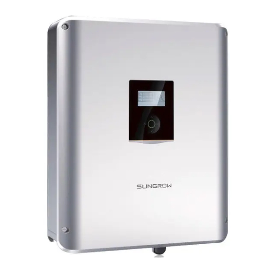
Any use other than the one described in this chapter is not permitted. SH5K-20 is a single-phase hybrid inverter applicable to both on-grid and off-grid PV systems. With the integrated Energy Management System (EMS), they can control and optimize the energy flow so as to increase the self-consumption of the system. - Page 17 Grid Monitoring: VDE 0126-1-1 VDE-AR-N 4105 SUNGROW POWER SUPPLY CO., LTD. WWW.SUNGROWPOWER.COM MADE IN CHINA Fig. 2-1 Inverter Appearance Name Description AC-Grid AC terminal for the connection to the utility grid. Two holes for the control cable and DI cable of Backup Ctrl the backup box STB5K-20.
-
Page 18: Energy Meter
2 System Solution User Manual D (170) W (457) Fig. 2-2 Dimensions (unit: mm) LCD Panel The LCD panel with an indicator and four buttons is on the front of the inverter. Fig. 2-3 LCD Panel Name Description Screen To display the information. Green and red can be indicated via the indicator, from Indicator which user can know the current status. -
Page 19: On-Grid System
User Manual 2 System Solution Front view Side view Fig. 2-4 Single-phase Meter Dimensions (unit: mm) Back view Side view Fig. 2-5 Three-phase Meter Dimensions (unit: mm) The single-phase Energy Meter and the three-phase Energy Meter are alternative in the delivery. The meter figures in this document have been created for the single-phase Energy Meter unless otherwise specified. - Page 20 Compatible with monocrystalline silicon, PV strings polycrystalline silicon, and thin-film without grounding. Inverter SH5K-20. Energy meter Measures the export power and communicates (single-phase for with the inverter via the RS485 port. example) Utility grid Grid grounding system types: TT, TN Household load Devices that consume energy.
- Page 21 User Manual 2 System Solution and battery is less than the load power. Energy Management during Night The battery discharges to provide energy to loads. If the battery is empty or there is not enough power from the battery system, the grid shall supply the power, first to emergency loads, then loads.
-
Page 22: Off-Grid System
2 System Solution User Manual If the Smart Energy Meter is abnormal or not equipped, the inverter will run normally, however, the battery can be charged but not allowed to discharge. In this case the feed-in power setting will be ineffective, and the DO function for optimized mode will be disabled. - Page 23 SBP4K8 Fig. 2-7 Inverter Application in an Off-grid System Declaration for Back-Up Function The following statement involves SUNGROW general policies about the hybrid inverters described in this document. For hybrid inverters, the electrical installation typically includes connection of the inverter to both PV modules and batteries. If there is no available power from batteries or PV modules in backup mode, the backup power supply will be automatically terminated.
-
Page 24: Retrofitting The Existing Pv System
The power generation from the existing PV inverter will be firstly provided to the loads and then charge the battery. With the energy management function of the SH5K-20, the self-consumption of the new system will be greatly improved. PV inverter... -
Page 25: Function Description
3 Function Description 3.1 Safety Function 3.1.1 Protection The protective functions are integrated in the inverter, including short circuit protection, grounding insulation resistance surveillance, residual current protection, anti-islanding protection, DC overvoltage / over-current protection, etc. 3.1.2 Earth Fault Alarm The inverter has integrated an earth fault dry-contact (DO2 relay) for the local alarm. -
Page 26: Power Derating
3 Function Description User Manual 3.2.1 Power Derating Power derating is a way to protect the inverter from overload or potential faults. In addition, the derating function can also be activated following the requirements of the utility grid. Situations requiring inverter power derating are: ... -
Page 27: External Demand Response
User Manual 3 Function Description Normally working area 230V Fig. 3-1 Grid Under-voltage Derating Export Power Limit Derating When the meter detects that the export power is greater than the limit value on the LCD, the inverter will reduce the output power within the specified range. Power Factor Derating When the power factor PF<1.0, the inverter will reduce the output power within a specified range. -
Page 28: Reactive Power Regulation
3 Function Description User Manual Tab. 3-1 Demand Response Modes (DRMs) Mode Explanation DRM0 The inverter is in the state of “Turn off”. DRM1 The import power from the grid is 0. DRM2 The import power from the grid is no more than 50 % of the rated power. DRM3 The import power from the grid is no more than 75 % of the rated power. -
Page 29: Load Control
The following kinds of batteries are compatible with the PV ESS. Further battery models will be made compatible in the furture. Li-ion battery from Sungrow, LG Chem, GCL, Pylon, BYD and TAWAKI. Lead-acid batteries which require manual configuration. -
Page 30: Charge Management
Other lead-acid < 30 V Configured by the customer * The SOC limits of Li-ion batteries except Sungrow batteries can be modified via the Webserver. For details about the Webserver, see “11 Appendix II: Visiting and Configuring the Webserver”. 3.3.2 Charge Management... - Page 31 Finish The battery under-voltage warning is cleared. The emergency charge command reported to the inverter is cleared. (only for Sungrow and BYD batteries) Tab. 3-4 Default SOC Conditions for Li-ion Battery Emergency Charge Type Trigger SOC Finishing SOC...
-
Page 32: Discharge Management
3 Function Description User Manual power. If the PV voltage is higher than the upper limit value of MPP voltage (560 V), the battery cannot charge. The hybrid inverter will start to charge the battery when the export power value exceeds a pre-defined threshold value of 70 W. 3.3.3 Discharge Management Discharge management can effectively protect the battery from deep discharging. -
Page 33: Battery Temperature Sensor (Pt1000)
User Manual 3 Function Description 3.3.5 Battery Temperature Sensor (PT1000) SH5K-20 has integrated a PT1000 temperature sampling port for lead-acid batteries. With the external PT1000 installed, SH5K-20 can sample the temperatures of the external environment or the battery cabinet. The system uses the sensor input to perform power derating, battery over-temperature and under-temperature protection. -
Page 34: Unpacking And Storage
Check the scope of delivery for completeness according to the packing list. Check the inner contents for damage after unpacking. Contact SUNGROW or the supplier in case of any damage or incompleteness. Do not dispose of the original packing case. It is recommended to store the inverter in it. -
Page 35: Scope Of Delivery
User Manual 4 Unpacking and Stor 4.2 Scope of Delivery Expansion plug set (x2) Wall-mounting bracket Inverter AC connector set Single-phase meter and CT cable Three-phase meter PV connectors (x2) Power supply cable (meter) RS485 cable (meter) Copper bar OT25-6 terminals M5 screws and washers CAN cable (battery) Wi-Fi module... -
Page 36: Inverter Storage
0 and 100 %. In case of stacking storage, the number of stacking layers should never exceed the limit marked on the outer side of the packing case (5 layers for SH5K-20). The packaging must be upright. ... -
Page 37: Mechanical Mounting
5 Mechanical Mounting 5.1 Safety during Mounting Make sure there is no electrical connection before installation. In order to avoid electric shock or other injury, make sure that holes will not be drilled over any electricity or plumbing installations. Risk of injury due to improper handling ... -
Page 38: Installation Environment Requirements
5 Mechanical Mounting User Manual IP65 5.2.1 Installation Environment Requirements The installation environment must be free of inflammable or explosive materials. The location should be not accessible to children. The ambient temperature and relative humidity must meet the following requirements. -
Page 39: Installation Clearance Requirements
User Manual 5 Mechanical Mounting the inverter. 5.2.4 Installation Clearance Requirements Reserve enough clearance around the inverter to ensure sufficient space for heat dissipation. 300mm 300mm 5.3 Installation Tools Installation tools include but are not limited to the following recommended ones. If necessary, use other auxiliary tools on site. - Page 40 5 Mechanical Mounting User Manual Protective gloves Dust mask Earplugs Goggles Insulated shoes Vacuum cleaner Heat shrink tubing Installation tools (recommended) Heat gun Hammer drill Rubber mallet Drill bit: Φ10 Electric screwdriver Phillips screwdriver Wire stripper Tool bit: M5 Specification: M5 Hydraulic plier Crimping tool Wrench for MC4 terminal...
-
Page 41: Moving The Inverter
User Manual 5 Mechanical Mounting Wire clipper RJ45 crimping tool Flat-blade screwdriver Torx screwdriver Socket wrench TX30 Open end: 10mm (for M6 bolts) 13mm (for M8 bolts) 16mm (for M10 bolts) 5.4 Moving the Inverter Before installation, remove the inverter from the packing case and move it to the installation site. - Page 42 5 Mechanical Mounting User Manual Self-tapping screw M6 Expansion tube Fender washer Spring washer Install the wall-mounting bracket with a torque of 9.0 Nm. Note that the depth of the holes should be about 70 mm. Be sure to adhere to the screw assembly sequence: self-tapping screw, spring washer, fender washer and bracket.
-
Page 43: Installing The Energy Meter
User Manual 5 Mechanical Mounting 5.6 Installing the Energy Meter The Energy Meter should be installed between the grid and the load. It supports a 35 mm DIN-rail installation, as shown in the following figure. Single-phase Energy Meter Three-phase Energy Meter Fig. -
Page 44: Electrical Connection
6 Electrical Connection 6.1 Safety Instructions Prior to any electrical connections, keep in mind that the inverter has dual power supplies. It is mandatory for the qualified personnel to wear personal protective equipments (PPE) during the electrical work. Danger to life due to a high voltage inside the inverter ... -
Page 45: Terminal Description
User Manual 6 Electrical Connection 6.2 Terminal Description Backup Ctrl Fig. 6-1 Terminals at the Bottom of the Inverter Decisive Voltage Label Description Classification AC terminal for connection to the utility AC-Grid DVC-C grid. Two holes for the control cable and DI Backup Ctrl DVC-A cable of the backup box STB5K-20. - Page 46 6 Electrical Connection User Manual Connection terminals on the inner configuration circuit board are shown below: Fig. 6-2 Configuration Circuit Board Inside the Inverter Decisive Tool Label Connection Voltage Requirements Classification Flat-head Backup screwdriver with C1, C2 DVC-A STB5K-20 an open end of 3 (for parallel Phillips...
-
Page 47: Additional Grounding Connection
User Manual 6 Electrical Connection 6.3 Additional Grounding Connection Since the inverter is transformerless, neither the negative pole nor the positive pole of the PV string must be grounded. Otherwise, the inverter will not operate normally. Connect the additional grounding terminal to the protective grounding point before AC cable connection, PV cable connection, and communication cable connection. - Page 48 6 Electrical Connection User Manual L = E + (2~3)mm 1: Heat shrink tubing 2: OT/DT terminal Remove the screw on the grounding terminal and fasten the cable with a screwdriver. Item Description Specification Cable socket Not included in the delivery scope. Screw M5×12 mm (3.0 Nm) The second PE conductor should be of the same...
-
Page 49: Ac Cable Connection
User Manual 6 Electrical Connection 6.4 AC Cable Connection 6.4.1 AC Side Requirements Residual Current Device With an integrated universal current-sensitive residual current monitoring unit included, the inverter will disconnect immediately from the mains power once a fault current with a value exceeding the limit is detected. However if an external residual current device (RCD) is mandatory, the switch must be triggered at a residual current of 300 mA (recommended), or it can be set to other values according to local regulations. -
Page 50: Installing The Ac Connector
6 Electrical Connection User Manual Fully insert the conductors to the corresponding terminal and tighten the screws with the torque 0.8 Nm. Pull cables outward check whether they firmly installed. Observe the terminal layout on the block. Avoid connecting the phase wires to "PE"... -
Page 51: Dc Cable Connection
User Manual 6 Electrical Connection Align the AC connector and the AC terminal and mate them together by hand until a “Click” is heard or felt. Connect the other ends. Connect “PE” conductor to the grounding electrode. Connect “L” and “N” conductors to the AC circuit breaker. The PE wire of the AC terminal must be directly connected to the grounding bar. - Page 52 6 Electrical Connection User Manual PV Input 1 Inverter Inside PV Input 2 Prior to connecting the inverter to PV inputs, the specifications in the following table should be met: Power Open-circuit Max. current Total Area Limit Voltage Limit input Power Limit Each Input for Each Input...
-
Page 53: Assembling The Pv Connector
PV input cables are of the same type. 6.5.2 Assembling the PV Connector SUNGROW provides corresponding plug connectors in the scope of delivery for quick connection of PV inputs. DC cables should be connected to the inverter via PV connectors which are included in the scope of delivery. -
Page 54: Installing The Pv Connector
6 Electrical Connection User Manual Procedure: Strip the insulation from each DC cable by 7 mm 8 mm. – 7 mm Positive Crimp Contact Assemble the cable ends with the crimping pliers. Negative Crimp Contact Lead the cable through the cable gland to insert into the insulator until it snaps into place. - Page 55 PV connectors to corresponding terminals only after ensuring polarity correctness. Electric arc or contactor over temperature may occur if the PV connectors are not firmly in place, and SUNGROW shall not be held liable for any damage caused due to this operation.
-
Page 56: Communication Connection
6 Electrical Connection User Manual (Optional) Install the copper Connect the PV connectors to for the parallel mode with a corresponding terminals until torque of 1.5 Nm. there is an audible click. Seal unused DC terminals with the terminal caps. 6.6 Communication Connection There are four ports and a Wi-Fi terminal on the bottom of the inverter, as shown in the following figure. -
Page 57: Ethernet Connection
User Manual 6 Electrical Connection 6.6.2 Ethernet Connection Connect the inverter to the PC through the Ethernet port to set up the Ethernet communication. The following figure shows the Ethernet connection without a router using the Webserver Explorer. Webserver Explorer Inverter Fig. -
Page 58: Wifi Connection
6 Electrical Connection User Manual Unscrew the swivel nut from Lead the cable through the any Com. port. cable gland and remove the cable jacket by 8 mm 15 mm. – Use the Ethernet crimper to crimp the cable and connect the cable to RJ45 plug according to TIA/EIA 568B, as shown below. -
Page 59: Meter Connection
Refer to the Quick User Manual delivered with the Wi-Fi module to configure the Wi-Fi. 6.7 Meter Connection The SUNGROW energy meter should be installed next to the main switch. This section mainly describes the cable connections on the inverter side. Refer to the quick guide delivered with the SUNGROW meter for the connections on the meter side. -
Page 60: Battery Connection
6 Electrical Connection User Manual Lead the cable through the cable gland. Plug the wires into terminals A2 and B2 on the inverter without tool tightening. Note: For reconnection, press the part as shown in the red circle so as to pull out the cable. -
Page 61: Connecting The Power Cable
User Manual 6 Electrical Connection 6.8.1 Connecting the Power Cable A fuse with the specification of 150 V/125 A (type: Bussmann BS88 125LET) is integrated to the BAT- terminal. A two-pole DC circuit breaker with over-current protection (voltage rating not less than 100 V and current rating not less than 100 A) should be installed between the inverter and the battery. -
Page 62: Connecting The Can Cable
Fasten the swivel nut with a torque of 5 Nm–6 Nm and connect the other end to the battery 6.8.2 Connecting the CAN Cable The CAN cable enables the communication between the inverter and the Li-ion battery from LG, Sungrow, GCL, Pylon (US2000B), BYD or TAWAKI. Procedure: Take cable (terminal marks CANH and CANL) from the packaging. -
Page 63: Connecting The Temperature Sensor
User Manual 6 Electrical Connection Plug wires into BAT_Com. corresponding terminals according the marks without tool tightening. CANH: blue (pin 4) CANH CANL CANL: white-blue (pin 5) Note: For reconnection, press the part as shown in the red circle so as to pull out the cable. -
Page 64: Stb5K-20 Connection (Eps)
6.9 STB5K-20 Connection (EPS) The backup box is installed between the SUNGROW meter and the hybrid inverter SH5K-20. If the backup box is installed, you should enable the EPS function and set the reserved capacity for Li-ion batteries via the LCD. For details, see “10.4.2 Setting the EPS Function”. -
Page 65: Connecting The Power Cables
STB5K-20. And it is the same for the PE lines. Connect terminals L1, N1 and PE to the grid, and connect terminals L4, N4 and PE to the AC connector and then to the AC terminal on the SH5K-20. Cross-section: 4 mm², cable diameter: 11 mm 14 mm –... - Page 66 6 Electrical Connection User Manual Unscrew the swivel nut from Backup Ctrl port. Lead the cable through the left hole. Backup control cable DI cable Plug the wires of the control cable into terminals C1 and C2 without tool tightening. STB5K-20 SH5K A lethal voltage of 230 Vac is present between C1 and C2 terminals.
-
Page 67: Do Connection
User Manual 6 Electrical Connection STB5K-20 SH5K Note: For reconnection, press the part as shown in the red circle so as to pull out the cable. Fasten the swivel nut with a torque of 5 Nm–6 Nm and connect the other end to the backup box. - Page 68 6 Electrical Connection User Manual Grid Manual Controlled by switch Load Inverter inside Contactor An AC contactor must be installed between the inverter and appliances. It is prohibited to connect the load directly to the DO port. The current of the DO dry contact should not be larger than 3 A. The DO node is not controlled once the inverter is powered off.
- Page 69 User Manual 6 Electrical Connection Remove the cable jacket and strip – 5 mm 8 mm the wire insulation. – 40 mm 50 mm Plug the wires into DO terminals without tool tightening. Note: COM1 NO1 COM2 NO2 For reconnection, press the part as shown in the red circle so as to pull out the cable.
-
Page 70: Commissioning
7 Commissioning 7.1 Inspection before Commissioning Check the following items before starting the system: The inverter DC switch and external circuit breaker are disconnected. The inverter should be accessible for operation, maintenance and service. Nothing is left on the top of the inverter or battery. The inverter is correctly connected to the external devices, and the cables are routed in a safe place or protected against mechanical damage. -
Page 71: Powering On The System
User Manual 7 Commissioning Start Press to enter the menu. Press to navigate through the menu. Press to confirm a selection. Modifying mode Selecting mode Press / to move Press / to move to the desired item. to the desired item. Press and the first digit of the Press... -
Page 72: Lcd Initial Settings
7 Commissioning User Manual Initial Settings Initial Settings Initial Settings Country Reactive Power Earth Fault Exit Time Battery Usage Time Zero-export EPS Setting 7.4 LCD Initial Settings Set the country code. For the code “AU”, select the grid standard as shown in the following figures. - Page 73 User Manual 7 Commissioning Parameter Default 2-Time (s) 0.20 0.20 0.20 0.20 0.20 0.20 0.20 Under-frequency * (Hz) 47.00 48.00 47.00 47.00 47.00 47.00 47.00 1-Time (s) 1.50 1.50 1.50 1.50 1.50 1.50 1.50 (Hz) 47.00 48.00 47.00 47.00 47.00 47.00 47.00 2-Time (s)
- Page 74 7 Commissioning User Manual − the lower limit is the rated power of the existing system; and − the upper limit is (5000 W + [rated power of the existing system]). − the value will synchronize with the settings for retrofitting an existing system “10.4.3 Adding the Existing System”...
- Page 75 User Manual 7 Commissioning (Optional) For lead-acid batteries, you should manually set the battery type. − Turn off the inverter via the LCD menu. Menu ON / OFF 5000 Run Info Confirm ‘OFF’? 3000 1900 ON / OFF Settings Running 16:37 −...
-
Page 76: Result Verification
7 Commissioning User Manual Parameter Description Range The upper limit of battery voltage when Over Vtg 48 V to 70 V charging The lower limit of battery voltage when Low Vtg 32 V to 48 V discharging Over Temp The upper limit of battery temperature 20℃... -
Page 77: System Decommissioning
8 System Decommissioning 8.1 Decommissioning the Inverter For maintenance or other service work, the inverter must be switched off. Proceed as follows to disconnect the inverter from the AC and DC power sources. Lethal voltages or damage to the inverter will follow if otherwise. 8.1.1 Disconnecting the Inverter Stop the inverter via the LCD menu. -
Page 78: Dismantling The Inverter
8.2 Decommissioning the Battery Decommission the battery in the system after the inverter is decommissioned, following the steps for a Li-ion battery or lead-acid battery below. SUNGROW is not liable for disposal of the battery. 8.2.1 Disconnecting Li-ion Battery Disconnect the DC circuit breaker between the battery and the inverter. -
Page 79: Disconnecting Lead-Acid Battery
User Manual 8 System Decommissioning 8.2.2 Disconnecting Lead-acid Battery 1. Disconnect the DC switch between the battery and the inverter. 2. Turn off the switch on the battery. 3. Disconnect all the cables between the battery and the inverter. -
Page 80: Troubleshooting And Maintenance
4. Check whether the DC input voltage exceeds the start voltage of the inverter. 5. If all of the above are OK, please contact SUNGROW. 1. A fault is not resolved. 2. Perform troubleshooting according to the fault type on the LCD screen. See “8.1.2 The LED indicator is lit red. -
Page 81: Maintenance
For any maintenance need, please contact SUNGROW. Otherwise, SUNGROW shall not be held liable for any damage caused. Servicing of the device in accordance with the manual should never be undertaken in the absence of proper tools, test equipments or the latest revision of the manual which has been clearly and thoroughly understood. -
Page 82: Routine Maintenance
There is a button battery on the inner PCB board of the LCD. Contact the SUNGROW Service Dept. for replacement when the relevant fault alarm occurs. Check the fastener, appearance, voltage, and resistance quarterly and... -
Page 83: Appendix I: Lcd Operation
16:37: Current system time. Neither the grid power nor the load power will be displayed on the main screen in case of no SUNGROW meter installed. If there is no button operation for: 1 minute, the LCD backlight is OFF;... -
Page 84: Lcd Menu
Whether the battery level is sufficient and the cable connection is correct. If no anomaly is found, disconnect the DC switch and the main switch to restart. If it still does not work, contact SUNGROW. 10.2 LCD Menu Abbreviations... - Page 85 User Manual 10 Appendix I: LCD Operation Abbreviation Complete Abbreviation Complete Constant Max. discharging current CSTVtgChrg MDCV charging voltage value Max. charging current DChrg Discharge MCCV value Prot. Protection Multi. Multiple Comm. Communication DChrgEndVtg Final discharg voltage System Enable The following figure shows the menu of the LCD display. Main Menu Run Info ON / OFF...
-
Page 86: Starting And Stopping The Inverter
10 Appendix I: LCD Operation User Manual (2) The value of battery SOH will be displayed as “--” for GCL batteries that do not have this parameter. The SOC value for lead-acid batteries is for reference only. (3) The DRM0 state will prohibit the “ON”. (4) The “Restart”... -
Page 87: Setting The Eps Function
20 s when the battery level is lower than the threshold value specified in the following table. Tab. 10-2 Threshold Values of Different Batteries Battery Type SOC Threshold ≤ 6 % Sungrow (retrofitting system) / LG ≤ 11 % ≤ 16 % ≤ 21 % Pylon (US2000B), TAWAKI ≤ 45 V... -
Page 88: Adding The Existing System
05000W For example, retrofit an existing PV system (rated power: 3000 W) with SH5K-20 hybrid inverter (rated power: 5000 W). The total export limit can be set from 3000 W to 8000 W. The export power limit setting and zero-export setting are from the same source. -
Page 89: Setting The Battery Usage Time
User Manual 10 Appendix I: LCD Operation 10.4.5 Setting the Battery Usage Time When there is no battery equipped in the system, a prompt will appear. For details, see step 5 in 7.4 LCD Initial Settings No Battery ! 10.4.6 Setting Forced Charge In the system without a battery, a Enable the function for the system with prompt will appear. - Page 90 10 Appendix I: LCD Operation User Manual Vmax-recover Fmax-recover After the grid voltage or frequency 253.0 50.15Hz recovers to the specified range, the Vmin-recover Fmin-recover corresponding error code displayed on 205.0V 47.50Hz the LCD will be cleared and the inverter will resume on-grid running. Power Ramp Rate: the ramp up/down rate of power Power Ramp Rate En.
-
Page 91: Setting Reactive Power Regulation
User Manual 10 Appendix I: LCD Operation 10.4.8 Setting Reactive Power Regulation For details, see step 4 in “7.4 LCD Initial Settings” and the section “12.2 Reactive Power Regulation”. 10.4.9 Setting Active Power Response For details, see “12.3 Active Power Response”. 10.4.10 Setting Limit Power Ramp The limit power ramp function is disabled by Limit P Ramp... - Page 92 10 Appendix I: LCD Operation User Manual Grid Inverter DO port Contactor COM1 DO relay Fig. 10-2 DO Operation in Timer Control ON/OFF Control In this mode, the system will control Load Control ON/OFF the load operation according to the Timer setting.
-
Page 93: Setting The Communication Parameters
User Manual 10 Appendix I: LCD Operation When the existing system is enabled, the upper limit of optimized power is the sum of the rated power of the hybrid inverter and the rated power of the existing PV system. ... -
Page 94: Testing Earth Fault
10 Appendix I: LCD Operation User Manual 10.4.13 Testing Earth Fault The DO2 relay will switch on automatically to signal the external alarm if a light indicator and/or buzzer is connected. The buzzer inside the inverter will also beep. 10.4.14 DRM Switch Setting The DRM function to the DRED (demand response DRM Switch enabling device) is enabled by default. -
Page 95: Setting The Country
User Manual 10 Appendix I: LCD Operation 10.6 Setting the Country The country setting is protected with a password. Each country code represents corresponding local protective parameters that have been preset before delivery. Press and Press to input the password Country 111. -
Page 96: Viewing The Error Codes
“Error” state on the Code 001 GRID main screen, press to view the current Type faults. Refer to section 5.2 in the SH5K-20 quick user manual for error description and troubleshooting. Refer to the following table for error type explanations. Error Type Explanation... - Page 97 User Manual 10 Appendix I: LCD Operation Viewing Error Record Press to turn pages and view all Error Record P1/1 error records. 18022708:55:27 1: the error is triggered. 18022707:11:21 0: the error is cleared.
-
Page 98: Appendix Ii: Visiting And Configuring The Webserver
11 Appendix II: Visiting and Configuring the Webserver 11.1 User and Authority The Webserver provides user permission and installer permission: The user permission (by default): the username is user and the password is 1111. Installer permission: Select the username installer through the drop-down list. The password is 2222. -
Page 99: Main Interface
User Manual 11 Appendix Visiting and Configuring the Webserver If there is no operation for 10 minutes, the system will automatically return to the login interface. The figures in this chapter are all with an installer’s permission. 11.2 Main Interface Fig. - Page 100 11 Appendix Visiting and Configuring the Webserver User Manual The default interface after login displays the read-only information. You can use the “Export” button to export data as a CSV file. The Serial Number (SN) of the running inverter is shown on the upper-left corner. History records: 10 records in each page, 100 records at most.
-
Page 101: Appendix Iii: As/Nzs 4777 Compliant
12 Appendix III: AS/NZS 4777 Compliant The inverter supports the demand response modes, the reactive power regulation, and the power quality response, as specified in the standard AS/NZS 4777. 12.1 Demand Response Modes 12.1.1 Connecting the inverter to a DRED The inverter has integrated a terminal block for connecting to a DRED. -
Page 102: Viewing The Drm State Via Lcd Menu
III: 12 Appendix AS/NZS 4777 Compliant User Manual The cable for connecting to the DRED is not included in the delivery. Use a TIA/EIA 568B standard network cable with a diameter of 3 mm 5.3 mm. – Procedure Unscrew the swivel nut from Lead the cable through the any Com. -
Page 103: Reactive Power Regulation
III: User Manual 12 Appendix AS/NZS 4777 Compliant In “Run Info” menu, Press Menu turn to the page showing DRM DRM State DRM1 Run Info information. Import Limit 100.0% ON / OFF Export Limit 100.0% Settings 12.2 Reactive Power Regulation Only qualified personnel can perform the power regulation settings. -
Page 104: Q(U)" Mode
III: 12 Appendix AS/NZS 4777 Compliant User Manual Parameter Explanation Default Range Upper Upper limit of the output power (in %) 100 % 50 %–100 % Power* *Lower Power <Upper Power General Q(P) Curve Default Q(P) Curve COS Ф COS Ф 100% Lower power Upper power... -
Page 105: Active Power Response
III: User Manual 12 Appendix AS/NZS 4777 Compliant Parameter Explanation Default Range Reactive power -030.0 Q4 Ref. -030.0 % -030.0 % at voltage V4 Q/Sn Grid voltage, V Fig. 12-2 Reactive Power Regulation Curve in Q(u) Curve (“AU” for example) 12.3 Active Power Response The submenu is as shown on the right. -
Page 106: Volt-Watt Response For Battery Charging
III: 12 Appendix AS/NZS 4777 Compliant User Manual Parameter Explanation Default Range Grid voltage V3 Ref. 250.0 V 244.0 V reference value 3 Grid voltage V4 Ref. 265.0 V 255.0 V reference value 4 Active power at P1 Ref. 100.0 % 100.0 % voltage V1 Active power at... - Page 107 III: User Manual 12 Appendix AS/NZS 4777 Compliant output power V1 Ref. 207.0V P1 Ref. 0.0% inverter will vary in response to V2 Ref. 220.0V 100.0% P2 Ref. the grid voltages. V3 Ref. 250.0V P3 Ref. 100.0% V4 Ref. 265.0V P4 Ref.
-
Page 108: Frq-Watt Response
III: 12 Appendix AS/NZS 4777 Compliant User Manual 12.3.3 Frq-Watt Response Tab. 12-6 Description of Frq-watt Parameters Parameter Description Default Range The Start frequency value for 50.00 Hz– OverFrq Start 50.25 Hz over-frequency response 55.00 Hz The Stop frequency value for 50.00 Hz–... - Page 109 III: User Manual 12 Appendix AS/NZS 4777 Compliant Response to a decrease in grid frequency: When there is a decrease in grid frequency which UnderFrq Start falls below the Start value (49.75 Hz), the inverter 49.75 Hz will reduce the sinking power from the grid linearly UnderFrq End with a decrease of frequency until the End value 49.00 Hz...
-
Page 110: Appendix Iv: Technical Data
13 Appendix IV: Technical Data 13.1 Inverter PV Input Data Max. PV input power 6500 W Max. PV input voltage 600 V Startup voltage 125 V Nominal input voltage 350 V MPP voltage range 125 V–560 V MPP voltage range for nominal 240 V–520 V power No. - Page 111 User Manual 13 Appendix Technical Data Total Harmonic Distortion (THD) < 3 % (of nominal power) DC current injection < 0.5 % (of nominal current) > 0.99 at default value at nominal power Power factor (adj. overexcited/leading–0.8 underexcited/lagging) Protection Anti-islanding protection AC short circuit protection Leakage current protection DC fuse (battery)
-
Page 112: Stb5K-20 (Backup Box)
13 Appendix Technical Data User Manual Backup Data Nominal voltage 230 Vac (± 2 %) Total harmonic factor output 2 % (full resistive load) Frequency range 50 Hz (±0.2 %) Switch time to emergency mode 0.8 overexcited/leading–0.8 Power factor underexcited/lagging Max. -
Page 113: Quality Assurance
Evidence During the warranty period, the customer shall provide the product purchase invoice and date. In addition, the trademark on the product shall be undamaged and legible. Otherwise, SUNGROW has the right to refuse to honor the quality guarantee. Conditions ... - Page 114 Model of the inverter Serial number of the inverter Error code/name Brief description of the problem China (HQ) Australia Sungrow Power Supply Co., Ltd Sungrow Australia Group Pty. Ltd. Hefei Sydney +86 551 65327834 +61 2 9922 1522 service@sungrowpower.com service@sungrowpower.com.au...
- Page 115 Sungrow Power Korea Limited Tokyo Seoul +81 3 6262 9917 +82 70 7719 1889 service@jp.sungrowpower.com service@kr.sungrowpower.com Malaysia Philippines Sungrow SEA Sungrow Power Supply Co., Ltd Selangor Darul Ehsan Mandaluyong City +60 19 897 3360 +63 9173022769 service@my.sungrowpower.com service@ph.sungrowpower.com Thailand Spain Sungrow Ibérica S.A.U.
- Page 116 13 Appendix Technical Data User Manual U.S.A, Mexico Sungrow Power UK Ltd. Sungrow USA Corporation Milton Keynes Phoenix +44 (0) 01908 414127 +1 833 747 6937 service@sungrow-emea.com techsupport@sungrow-na.com Belgium, Netherlands Vietnam Luxembourg (Benelus) Sungrow Vietnam 08000227012 (only Hanoi Netherlands) +84 918 402 140 service@sungrow-emea.com...
Need help?
Do you have a question about the SH5K-20 and is the answer not in the manual?
Questions and answers