
Related Manuals for Sungrow SH3K6-30


Summary of Contents for Sungrow SH3K6-30
- Page 1 User Manual SH3K6 / SH4K6 / SH5K-30 Grid-Connected Hybrid Inverter SH3.6_4.6_5K-30-UEN-Ver11-201908 Version:1.1...
-
Page 3: About This Manual
Documents must be stored carefully and be available at all times. All rights to the content of this manual are owned by Sungrow Power Supply Co., Ltd. (hereinafter “SUNGROW”). No part of this document can be modified, distributed, reproduced or published in any form or by any means without prior written permission from SUNGROW. - Page 4 Symbol Explanation Indicates a hazard with a medium level of risk that, if not avoided, could result in death or serious injury. Indicates a hazard with a low level of risk that, if not avoided, could result in minor or moderate injury. Indicates a situation that, if not avoided, could result in equipment or property damage.
-
Page 5: Table Of Contents
Contents About This Manual ..............I Safety ..................1 System Solution ..............5 PV Energy Storage System (PV ESS) ........8 Retrofitting System ..............11 Function Description ............13 Safety Function ............... 13 3.1.1 Protection ................13 3.1.2 Earth Fault Alarm ..............13 3.1.3 SPI and Auto Test (“IT”) ............ - Page 6 Location Requirements ............28 Tools ..................30 Installing the Inverter ..............32 Installing the Energy Meter ............33 Electrical Connection ............34 Terminal Description ..............34 Grounding the Inverter ............. 36 Energy Meter Connection ............37 6.3.1 On the Meter Side ..............37 6.3.2 On the Inverter Side ..............
- Page 7 LCD Initial Settings ..............66 7.4.1 Setting the Country Code ............66 7.4.2 Adding the Existing Inverter ............. 68 7.4.3 Setting Feed-in Power ............. 69 7.4.4 Setting System Time ............... 69 7.4.5 Setting Backup Function............69 7.4.6 Setting Reactive Power Regulation ("DE") ......70 7.4.7 Initializing ................
- Page 8 10.4.6 Setting the Battery Usage Time ..........92 10.4.7 Setting Forced Charge ............92 10.4.8 Setting the Protective Parameters ......... 93 10.4.9 Setting Reactive Power Regulation ........95 10.4.10 Setting Active Power Response .......... 95 10.4.11 DO Function Setting ............95 10.4.12 Setting the Communication Parameters ......
- Page 9 13.1 Inverter .................. 117 13.2 Energy Meter ................. 119 13.3 Quality Assurance ..............120...
-
Page 11: Safety
1 Safety General Safety The inverter has been designed and tested strictly according to international safety regulations. Read all safety instructions carefully prior to any work and observe them at all times when working on or with the inverter. Incorrect operation or work may cause: ... - Page 12 1 Safety User Manual Symbol Explanation There is a danger from a hot surface that may exceed 60°C. Danger to life due to high voltages! Only qualified personnel can open and service the inverter. Check the user manual before service! Regulatory compliance mark.
- Page 13 User Manual 1 Safety Risk of inverter damage or personal injury Do not pull out PV connectors, AC connector or battery connectors while the inverter is running. De-energize from all power sources. Wait 10 minutes for the internal capacitors to discharge. Verify that there is no voltage or current before pulling any connector.
- Page 14 1 Safety User Manual Provide sufficient ventilation for the battery system to prevent flames and sparks from the explosive hydrogen gas that the batteries release. Due to the dangers of hydrogen gas and battery electrolyte: locate batteries in a designated area, complying with the local regulations;...
-
Page 15: System Solution
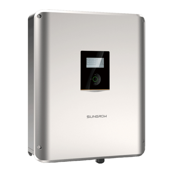
Inverter The type description is as follows: Inverter version Code of power level Code of Sungrow hybrid inverter Tab. 2-1 Power Level Description Type Nominal Output Power Nominal Grid Voltage SH3K6-30... - Page 16 Grid Monitoring: VDE 0126-1-1 VDE-AR-N 4105 SUNGROW tOW9R SUttLY /O., LT5. WWW.SUNGROWtOW9R./Oa aA59 IN /IINA Fig. 2-1 Inverter Appearance Name Description To feed power into the utility grid Grid terminal The emergency loads also can be supplied from the grid.
- Page 17 User Manual 2 System Solution The following figure shows the dimensions of the inverter. D (170) W (457) Fig. 2-2 Dimensions (unit: mm) The LCD panel with an indicator and four buttons is on the front of the inverter. Fig. 2-3 LCD Display Panel Name Description Screen...
-
Page 18: Pv Energy Storage System (Pv Ess)
2 System Solution User Manual Energy Meter The SUNGROW Energy Meter is installed next to the main switch to detect the electrical measured values at the grid-connected point. It communicates with the inverter via an RS485 connection. The dimensions are shown below. - Page 19 Tab. 2-2 System Compositions Item Description Remark Monocrystalline silicon, polycrystalline PV strings silicon, and thin-film without grounding Inverter SH3K6-30 / SH4K6-30 / SH5K-30 Sungrow Energy Measures feed-in power Meter (single-phase communicates with the inverter via the for example) RS485 port.
- Page 20 2 System Solution User Manual Energy Management during Daytime The energy management system (EMS) works in self-consumption mode by default. The PV power will go to emergency loads and house loads first, then the battery. Then if the battery is fully charged the excess will go to the grid, the feed-in power should be not more than the limit value in zero-export setting in initial commissioning.
-
Page 21: Retrofitting System
User Manual 2 System Solution Emergency loads If the meter is abnormal or not equipped, the inverter can run normally, the battery can be charged but not allowed to discharge, the feed-in power setting on the LCD display will be ineffective, and the DO function of optimized mode will be disabled. - Page 22 2 System Solution User Manual Note: In zero-export scenario, the hybrid inverter can only promise no power exported to grid itself but not promise the PV inverter zero-export. Please contact the PV inverter manufacture for its zero-export solution. PV modules for hybrid inverter are optional. The existing PV inverter provides power to the PV ESS, as the power flow shown on 5000...
-
Page 23: Function Description
3 Function Description 3.1 Safety Function 3.1.1 Protection The protective functions are integrated in the inverter, including short circuit protection, grounding insulation resistance surveillance, residual current protection, anti-islanding protection, DC overvoltage / over-current protection, etc. 3.1.2 Earth Fault Alarm The inverter has integrated a multiple-function dry-contact (DO relay), which can be used for the external alarm for an earth fault. -
Page 24: Energy Conversion And Management
3 Function Description User Manual 3.2 Energy Conversion and Management The inverter converts the DC power from the PV strings or the battery to the AC power, which conforms to the grid requirements. It also transmits the DC power from the PV panel to the battery. With the bidirectional converter integrated inside, the inverter can charge or discharge the battery. -
Page 25: Drm ("Au"/"Nz")
User Manual 3 Function Description Refer to “12 Appendix III: Active Power Response” for over-voltage curve. The following figure shows the under-voltage derating curve. Normally working area 230V Fig. 3-1 Grid Under-voltage Derating Feed-in Power Limit Derating When the meter detects that the feed-in power is greater than the limit value on the LCD, the inverter will reduce the output power within the specified range. -
Page 26: Regular Operational Voltage Range
3 Function Description User Manual Tab. 3-1 Demand Response Modes (DRMs) Mode Explanation DRM0 The inverter is in the state of “Turn off”. DRM1 The import power from the grid is 0. DRM2 The import power from the grid is no more than 50 % of the rated power. DRM3 The import power from the grid is no more than 75 % of the rated power. - Page 27 User Manual 3 Function Description Tab. 3-2 Operational Voltage Parameter Description Parameter Explanation Grid-connection The lower voltage limit for initial start-up. The upper voltage limit for initial start-up. The lower voltage limit for reconnection. The upper voltage limit for reconnection. Minimum observation time.
-
Page 28: Regular Operational Frequency Range
3 Function Description User Manual When the voltage level is out of the operational levels shown in the table, the inverter will disconnect from the grid. If a disturbance lasts less than the required disconnection time, the inverter can reconnect to the grid if the voltage level goes back to normal levels after the disturbance. - Page 29 User Manual 3 Function Description Parameter Description Under-frequency protection time. Over-frequency protection time. Tab. 3-6 Default Values of Operational Frequency Parameter Parameter F1 (Hz) 47.52 47.50 47.50 48.00 49.90 F2 (Hz) 50.10 50.10 50.10 50.10 50.10 F3 (Hz) 47.52 47.50 47.50 48.00 49.90...
-
Page 30: Reactive Power Regulation
3 Function Description User Manual (2) After the low frequency, the inverter will only reconnect to the grid again when the frequency returns to 59.9 Hz, respecting the reconnection waiting time of 300 seconds. When the grid frequency is more than 60.5 Hz and less than 62 Hz, the inverter will reduce the active feed-in power. -
Page 31: Load Control
3.3 Battery Management The following kinds of batteries are compatible with the PV ESS. Li-ion battery from SUNGROW, LG Chem, GCL, Pylon, BYD and TAWAKI. Lead-acid batteries which require manual configuration. To maximize the battery life, the inverter will perform battery charge, discharge, and maintenance management basing on the battery state. -
Page 32: Charge Management
Other lead-acid < 30 V Configured by the customer * The SOC limits of Li-ion batteries except SUNGROW batteries can be modified via iSolarCloud App or the iSolarCloud server by qualified personnel. 3.3.1 Charge Management A hybrid inverter should provide a means for temperature compensation of the battery charge voltages. - Page 33 A battery under-voltage warning is triggered. An emergency charge command is reported to the inverter. (only for SUNGROW and BYD batteries) All the following conditions are met: SOC ≥ (Min. SOC) – 1% (valid only when the Min. SOC is ≥...
-
Page 34: Discharge Management
3 Function Description User Manual If the PV voltage is higher than the upper limit value of MPP voltage 560 V, the battery cannot charge. The hybrid system will start to charge the battery when the feed-in power value exceeds a threshold value of 70 W. 3.3.2 Discharge Management Discharge management can effectively protect the battery from deep discharging. -
Page 35: Unpacking And Storing
Check the delivery contents for completeness according to the packaging list. Check the inner contents for any visible damage. Contact SUNGROW or the distributor in case of any damaged or missing components. It is the best choice to store the inverter in the original packaging. So, do not dispose of it. -
Page 36: Delivery Contents
4 Unpacking and Storing User Manual 4.2 Delivery Contents Expansion plug set (x2) Wall-mounting bracket Inverter AC connector set Single-phase meter and CT cable Three-phase meter Backup connector set PV connectors (x2) Power supply cable (meter) RS485 cable (meter) OT25-6 terminals M5 screws and washers CAN cable (battery) Wi-Fi module... -
Page 37: Storing The Inverter
User Manual 4 Unpacking and Storing The power supply cable is only delivered for the single-phase Energy Meter. One is for external grounding and the other two are for securing the inverter. The documents include the Quick Installation Guide, quality certificates, packaging list and product test reports. -
Page 38: Mechanical Mounting
5 Mechanical Mounting In order to avoid electric shock or other injury, be sure there is no electricity or plumbing installations before drilling holes. Risk of injury due to improper handling The weight can cause injuries, serious wounds, or bruise. ... - Page 39 User Manual 5 Mechanical Mounting Max. RH Max. Min. +100% +60°C -25°C Only mount the inverter on a non-flammable surface or a wooden structure. Keep away from flammable materials or gas. Do not enclose the inverter into a tight confinement. Flammable material or Flammable wall Closed Cabinet...
-
Page 40: Tools
5 Mechanical Mounting User Manual Clearance requirement and multiple installation: 300mm 300mm 5.2 Tools Installation tools include but are not limited to the following recommended ones. If necessary, use other auxiliary tools on site. General tools (recommended) Packaging tape Marker Measuring tape Utility knife Multimeter... - Page 41 User Manual 5 Mechanical Mounting Earplugs Goggles Insulated shoes Vacuum cleaner Heat shrink tubing Installation tools (recommended) Heat gun Hammer drill Rubber mallet Drill bit: φ10 Electric screwdriver Phillips screwdriver Wire stripper Tool bit: M5 Specification: M5 Hydraulic plier Crimping tool Wrench for MC4 terminal Crimping range:...
-
Page 42: Installing The Inverter
5 Mechanical Mounting User Manual 5.3 Installing the Inverter Inverter is installed on the wall by means of wall-mounting bracket and the expansion plug sets. The expansion plug set shown below is recommended for the installation. Self-tapping screw M6 Expansion tube Fender washer Spring washer Install the wall-mounting bracket. -
Page 43: Installing The Energy Meter
Nm) (3.0 N m) 5.4 Installing the Energy Meter The SUNGROW Energy Meter should be installed between the grid and the load. It supports a 35 mm DIN-rail installation, as shown in the following figure. Single-phase Energy Meter Three-phase Energy Meter... -
Page 44: Electrical Connection
6 Electrical Connection This chapter mainly describes the cable connections on the inverter side. Danger to life due to a high voltage inside the inverter Make sure that the cables are not live before electrical connection. Do not turn on the AC circuit breaker until all the electrical connections are completed. - Page 45 User Manual 6 Electrical Connection Label Description To feed power into the utility grid GRID The emergency loads also can be supplied from the grid. BACKUP To connect emergency loads PV1+, PV1-, PV2+, Terminals for the DC cables PV2- ON, OFF DC switch Cable glands for Ethernet, RS485, CAN, DO, DRM and Com.
-
Page 46: Grounding The Inverter
6 Electrical Connection User Manual Label Connection BAT+, BAT- Battery 6.2 Grounding the Inverter A second protective earth (PE) terminal is equipped at the side of the inverter. Be sure to connect this PE terminal to the PE bar for reliable grounding and ensure that the grounding resistance should be less than 10 Ohm. -
Page 47: Energy Meter Connection
User Manual 6 Electrical Connection 6.3 Energy Meter Connection 6.3.1 On the Meter Side For Single-phase Energy Meter For the single-phase meter, with the signal from the 1-phase sensor, the inverter determines the energy exchange with the utility grid on one phase. The CT clamp of 1-phase sensor can be placed before or after the main switch. - Page 48 6 Electrical Connection User Manual Make sure that the 1-phase sensor is installed in the right direction: the arrow on the sensor must point away from the grid towards the load. For Three-phase Energy Meter The following figures show two connection examples for the three-phase energy meter in the PV system.
-
Page 49: On The Inverter Side
User Manual 6 Electrical Connection Strip the insulation from the power wires by 10 mm. Then connect the wires to the terminals on the Energy Meter, as shown below. (Cross-section: 10 mm to 25 mm Load side Grid side The line conductor L1 supplies power to the Energy Meter. At least the line conductor L1 and the neutral conductor must be connected to the Energy Meter. -
Page 50: Grid Connection
6 Electrical Connection User Manual Unscrew the swivel nut from any Com. Port. Lead the cable through the cable gland. Plug the wires into terminals A2 and B2 on the inverter without tool tightening. Note: For reconnection, press the part as shown in the red circle so as to pull out the cable. -
Page 51: Assembling The Ac Connector
User Manual 6 Electrical Connection However if an external residual current device (RCD) is mandatory, the switch must be triggered at a residual current of 300 mA or higher. Cable Requirements Cross-section: 3 * 6 mm², cable diameter: 11 mm - 15 mm. All the AC cables should be equipped with correctly colored cables for distinguishing. -
Page 52: Installing The Ac Connector
6 Electrical Connection User Manual Fully insert the conductors corresponding terminal and tighten the screws with the torque 0.8 Nm. Pull cables outward to check whether they are firmly installed. Observe the terminal layout of terminal block. Do not connect the phase lines to “PE” terminal, otherwise the inverter will not function properly and the loss of any or all the warranty rights may follow. -
Page 53: Pv Connection
User Manual 6 Electrical Connection Install circuit breaker at the AC output Type Specification of the inverter. In the SH3K6-30 40 A systems with multiple SH4K6-30 45 A inverters, protect each SH5K-30 45 A inverter with a separate circuit breaker. - Page 54 6 Electrical Connection User Manual maximum power. PV Input 1 Inverter Inside PV Input 2 Prior to connecting the inverter to PV inputs, the specifications in the following table should be met: Power Open-circuit Short circuit Total Area Limit Voltage Limit Current Limit Power Limit Each Input...
-
Page 55: Connecting The Inverter To The Pv Strings
User Manual 6 Electrical Connection To avoid the power unbalance of two inputs or input load-restriction, ensure the two PV input cables are of the same type. 6.5.2 Connecting the Inverter to the PV Strings All DC cables are equipped with water-proof direct plug-in connectors, which match the DC terminals at the bottom of the inverter. - Page 56 6 Electrical Connection User Manual The inverter will not function properly if the PV polarities are reversed. If the PV connectors are not assembled into place, it may cause an arc or overheat. The loss caused by this issue will void the warranty. Installing the PV Connector Rotate the optional DC switch at the bottom to the “OFF”...
-
Page 57: Communication Connection
User Manual 6 Electrical Connection 6.6 Communication Connection There are three ports and a Wi-Fi terminal on the bottom of the inverter, as shown in the following figure. Fig. 6-3 Communication Ports and Terminal Ethernet function: Through the Modbus TCP/IP protocol, the EMS or the Control Box from the third party can fully control the on/off, derating, charging and discharging of the inverter. - Page 58 6 Electrical Connection User Manual Internet iSolarCloud server Inverter Router/Switch Remote Local access iSolarCloud App iSolarCloud Fig. 6-4 Ethernet Connection with a Router Cable Requirements Use a TIA/EIA 568B standard network cable with a diameter of 3 mm 5.3 mm. –...
- Page 59 User Manual 6 Electrical Connection Use the Ethernet crimper to crimp the cable and connect the cable to RJ45 plug according to TIA/EIA 568B, as shown below. RJ45 Port RJ45 plug Corresponding Relationship Between Cables and Pins: Pin 1: White-orange; Pin 2: Orange;...
-
Page 60: Wi-Fi Connection
6 Electrical Connection User Manual Lead the cable through the cable gland. Install the RJ45 plug to the Ethernet port. Ethernet Fasten the swivel nut and connect the other end to the socket of the switch or the router. 6.6.2 Wi-Fi Connection Unscrew the waterproof lid from the Wi-Fi terminal. - Page 61 User Manual 6 Electrical Connection Cable Requirements Cross-section: 2*0.5 mm², cable diameter: 3 mm 5.3 mm – Procedure Unscrew the swivel nut from any Com. port. Lead the cable through the cable gland. Remove the cable jacket and – 5 mm 7 mm strip the wire insulation.
-
Page 62: Battery Connection
6 Electrical Connection User Manual 6.7 Battery Connection This section mainly describes the cable connections on the inverter side. Refer to the instructions supplied by the battery manufacturer for the connections on the battery side. Only use properly insulated tools to prevent accidental electric shock or short circuits. -
Page 63: Connecting The Can Cable
Be sure to adhere to the following screw assembly sequence: screw head, spring washer, fender washer, OT terminal. 6.7.2 Connecting the CAN Cable The CAN cable enables the communication between the inverter and the Li-ion battery from LG, Sungrow, GCL, Pylon (US2000B), BYD or TAWAKI. - Page 64 6 Electrical Connection User Manual Procedure Take cable (terminal marks CANH and CANL) from the packaging. Unscrew the swivel nut from any Com. port. Lead the cable through the cable gland. Plug wires into BAT_Com. corresponding terminals according the marks without tool tightening.
-
Page 65: Emergency Load Connection (Backup)
User Manual 6 Electrical Connection 6.8 Emergency Load Connection (Backup) Cable cross-section: 3 * 4.0 mm² – 3 * 6.0 mm², cable diameter: 10.5 mm - 15 All the AC cables should be equipped with correctly colored cables for distinguishing. Please refer to related standards about the wiring color. Lead the AC cable through the cable gland and the housing. -
Page 66: Do Connection
6 Electrical Connection User Manual Align the AC connector and the AC terminal and mate them together by hand until a “Click” is heard or felt. Connect the other ends to the emergency loads. Pull all the lines outward to check whether they are firmly installed. 6.9 DO Connection The inverter has one DO relay with multiple functions as follows: ... - Page 67 User Manual 6 Electrical Connection Relay Trigger condition Description Once the inverter receives the earth Earth fault fault signal, the relay closes the The earth fault occurs. alarm contact. The relay remains triggered until the fault is removed. Grid Manual Controlled by switch Load...
-
Page 68: Drm / Spi Connection
6 Electrical Connection User Manual Lead the cable through the cable gland. Remove the cable jacket and strip – 5 mm 8 mm the wire insulation. – 40 mm 50 mm Plug the wires into DO terminals without tool tightening. COM NO Note: For reconnection, press the part... - Page 69 User Manual 6 Electrical Connection DRM terminal The modes from DRM0 to DRM8 are supported by the inverter and the information is marked on the label located near the DRM terminals. Tab. 6-1 Method of Asserting DRMs Mode Asserted by Shorting Terminals DRM0 RefGen or Com/DRM0 DRM1...
-
Page 70: Spi Connection ("It")
6 Electrical Connection User Manual Lead the cable through the cable gland. Remove the cable jacket by 40 mm to 50 mm and strip the wire insulation by 5 mm 7 mm. – Plug the wires into the corresponding terminals without tool tightening, as shown below. - Page 71 User Manual 6 Electrical Connection following functions: Maximum/minimum frequency protection; Ability to receive signals aimed at changing the frequency protection thresholds and to receive the command of remote shutdown. Interface SPI Function Receive external signal/command to change the frequency protection parameters or shutdown the Ethernet inverter.
- Page 72 6 Electrical Connection User Manual 5 mm 7 mm – 40 mm 50 mm – Fig. 6-6 RS485 Connection to External Device Note: For reconnection, press the part as shown in the red circle so as to pull out the cable. Local Control In this mode, the inverter is in the absence of a communication “always on”...
- Page 73 User Manual 6 Electrical Connection Local Control External Control Explanation Maximum frequency 1 (F>) (Hz) 51.50 50.50 51.50 50.50 Maximum frequency 1 (F>) tripping time (s) 0.10 Maximum frequency 2 (F>>) (Hz) 51.50 51.50 51.50 51.50 Maximum frequency 2 (F>>) tripping time 0.10 ...
-
Page 74: Commissioning
7 Commissioning Proper commissioning is essential for the system to protect it against fires, injury and electric shock. 7.1 Inspection before Commissioning Check the following items before starting the system: All the installation sites are convenient for operation, maintenance and service. -
Page 75: Powering On The System
User Manual 7 Commissioning Start Press to enter the menu. Press to navigate through the menu. Press to confirm a selection. Modifying mode Selecting mode Press / to move Press / to move to the desired item. to the desired item. Press and the first digit of the Press... -
Page 76: Lcd Initial Settings
7 Commissioning User Manual Initial Setting Initial Setting Initial Setting Country Time Exit Existing Inverter Backup Setting Zero-export Reactive Power − Countries except Germany (“DE”) Initial Setting Initial Setting Country Time Existing Inverter Backup Setting Zero-export Exit 7.4 LCD Initial Settings 7.4.1 Setting the Country Code Countries Australia (“AU”) and New Zealand (“NZ”) Press... - Page 77 User Manual 7 Commissioning Parameter Default Under-voltage 180.0 200.0 180.0 180.0 180.0 180.0 180.0 1-Time (s) 1.80 1.80 1.80 1.80 1.80 1.80 180.0 200.0 180.0 180.0 180.0 180.0 180.0 2-Time (s) 1.80 1.80 1.80 1.80 1.80 1.80 Over-frequency (Hz) 52.00 52.00 52.00 52.00...
-
Page 78: Adding The Existing Inverter
7 Commissioning User Manual Country Grid Grade Prot. Stage Vgrid-max 242.0V Vgrid-min 176.0V 220V Single Stage Country: [ BRA ] Fgrid-max 62.00Hz Multi. Stage 240V Fgrid-min 57.50Hz Tab. 7-4 Default Parameters for Brazil Default / Range Parameter Explanation 220 V Grid 240 V Grid Grid over-voltage... -
Page 79: Setting Feed-In Power
User Manual 7 Commissioning 7.4.3 Setting Feed-in Power ON: no power could be fed into the Zero-export Partial grid. Feed-in Pwr[W] 05000 OFF: all system output power could Partial be fed into the grid. Partial: partial of the output power could be fed into the grid. ... -
Page 80: Setting Reactive Power Regulation ("De")
7 Commissioning User Manual 7.4.6 Setting Reactive Power Regulation ("DE") OFF: Reactive Power The reactive power regulation function is disabled. The power factor (PF) is limited to +1.000. Q(P) Q(U) “PF” mode: PF Setting The inverter is capable of operating with fixed power factor. The PF ranges from 0.8 leading to 0.8 lagging. -
Page 81: Result Verification
7.5.1 Energy Meter Installation and Connection For Incorrect Installation Position Make sure that the 1-phase sensor of the Sungrow Energy Meter should be placed to the phase line (L) from the main switch. If otherwise, the energy flow indicated on the LCD will be wrong. - Page 82 7 Commissioning User Manual Fig. 7-2 Correct CT Installation for Single-phase Energy Meter Load side Grid side Load side Grid side Fig. 7-3 Correct Power cable connection for Three-phase Meter Action LCD Explanation Correct Reverse Method 1: Turn off all the household loads. 4000 4000 4000...
-
Page 83: Battery Information
Press Press Run Info 2000 ON / OFF Settings Running 12:30 6 12 Scroll pages by pressing Input Mode Indep. Li-ion Sungrow Bat Tmp 36.1°C Bat Cap 4.8kWh Bat SOC 99.9% Self Csmp 89.9% CO2 Reduced 58kg Bat SOH 100.0% If the battery type or capacity setting is inconsistent with the actual, the charge/discharge current may be less than the actual charge/discharge ability. -
Page 84: Troubleshooting And Maintenance
4. Check whether the DC input voltage exceeds the start voltage of the inverter. 5. If all of the above are OK, please contact SUNGROW. 1. A fault is not resolved. 2. Perform troubleshooting according to the fault type on the LCD screen. See “8.1.2 The LED indicator is lit red. - Page 85 User Manual 8 Troubleshooting and Maintenance For Inverter Side Code Specification Troubleshooting 1. Check the grid voltage. Grid over-voltage. 2. If the grid voltage exceeds the The grid voltage exceeds the permissible range, consult the protective value. (stage I) utility grid for a solution. Transient over-voltage on-grid mode.
- Page 86 45 ℃ . If not, please upper limit. contact SUNGROW for a solution. Wait minutes inverter Relay fault on the grid side. recovery or restart the system. 1. Check whether the PV cable connection is intact.
- Page 87 1. Check whether the power cable connections are correct. Sungrow single-phase Warning reverse cable meter, check whether the CT connection of the Sungrow clamp of the 1-phase sensor is Meter. correctly placed. Refer to “7.5.1 Energy Meter Installation and Connection”. hardware over-current fault.
- Page 88 Specification Troubleshooting enclosure is reliably connected. 3. If there is an access to the ground, and the error persists, please contact SUNGROW for a solution. DC injection over-voltage fault The inverter will recover once the in the off-grid mode. DC injection voltage falls below The DC injection of INV voltage the recovery value.
- Page 89 1. Check whether the power cable connections of the meter are correct. Abnormal communication 2. Check whether the RS485 warning of the Sungrow Meter. connection is correct. (Inverter normally 3. Check if the 120 Ohm (2) connected to the grid.) resistor for RS485_2 is pushed to “ON”...
- Page 90 8 Troubleshooting and Maintenance User Manual Code Specification Troubleshooting 2. Check whether the inverter is installed in sunlight or the ambient temperature enclosure exceeds 45℃. 3. Restart the system. The system will resume once the hardware over-current battery charge/discharge current fault.
- Page 91 3. Force a shutdown and restart the over-current permanent inverter and battery system. fault. 4. Wait a moment for system recovery or restart the system. Restart the system, if the fault persists, competing please contact SUNGROW failure. solution. Mismatched software Contact SUNGROW for a solution. version.
- Page 92 8 Troubleshooting and Maintenance User Manual Code Specification Troubleshooting Restart the system, if the fault persists, Software self-verifying please contact SUNGROW failure. solution. inverter normally connected grid Battery cell over-voltage charge/discharge has stopped. fault. 2. Wait a moment for system recovery or restart the system.
-
Page 93: Maintenance
Lethal voltage still exists in the inverter. Please wait at least 10 minutes and then perform maintenance work. There is a button battery on the inner PCB board of the LCD. Contact SUNGROW for replacement when the relevant fault alarm occurs. Check the fastener, appearance, voltage, and resistance quarterly and annually. -
Page 94: System Decommissioning
9 System Decommissioning 9.1 Decommissioning the Inverter Please strictly follow the following procedure. Otherwise it will cause lethal voltages or unrecoverable damage to the inverter. Powering off the Inverter Stop the inverter via the LCD menu. For details, see “10.3 Starting and Stopping the Inverter”. -
Page 95: Decommissioning The Battery
User Manual 9 System Decommissioning Dismantling the Inverter Refer to Chapter 5 and Chapter 6, dismantle the cables in reverse procedure. Remove the wall-mounting bracket from the wall if necessary. Disposing of the Inverter Users should take the responsibility for the disposal of the inverter. Some parts and devices of the inverter, such as, LCD displayer, batteries, capacitors, may cause environment pollution. -
Page 96: Appendix I: Lcd Operation
12:30: Current system time. Neither the grid power nor the load power will be displayed on the main screen in case of no Sungrow meter installed. If there is no button operation for: 1 minute, the LCD backlight is OFF;... -
Page 97: Lcd Menu
Whether the battery level is sufficient and the cable connection is correct. If no anomaly is found, disconnect the DC switch and the main switch to restart. If it still does not work, contact SUNGROW. 10.2 LCD Menu Abbreviations... - Page 98 10 Appendix I: LCD Operation User Manual Abbreviation Complete Abbreviation Complete Max. discharging current Ver. Version MDCV value Constant Max. charging current CSTVtgChrg charging MCCV value voltage DChrg Discharge Multi. Multiple Prot. Protection DChrgEndVtg Final discharg voltage Communicatio Comm. Enable The following figure shows the menu of the LCD display.
-
Page 99: Starting And Stopping The Inverter
User Manual 10 Appendix I: LCD Operation 10.3 Starting and Stopping the Inverter Notice: ON / OFF The Restart item will appear only if an unrecoverable fault occurs. Confirm your choice by pressing ENT. Restart Confirm ‘OFF’ ? Confirm ‘ON’? Warning: BACKUP is on Confirm ‘Restart’? When the grid is on! -
Page 100: Setting The Backup Function
20 s when the battery level is lower than the threshold value specified in the following table. Tab. 10-2 Threshold Values of Different Batteries Battery Type SOC Threshold ≤ 6 % Sungrow (retrofitting system) / LG ≤ 11 % ≤ 16 % ≤ 21 % Pylon (US2000B), TAWAKI ≤ 45 V Lead-acid 10.4.3 Adding the Existing Inverter... - Page 101 User Manual 10 Appendix I: LCD Operation Press to select and Press to confirm. Battery Type Press No Battery Setting completed ! Li-ion Other Battery For lead-acid batteries, you should Only qualified pers- manually set the battery type. onnel are allowed adjust relevant param- eters.
-
Page 102: Setting The Battery Usage Time
10 Appendix I: LCD Operation User Manual Parameter Description Range The voltage at which the discharging is DChrgEndVtg 30 V to 53 V stopped The parameters can only be set by qualified personnel. Consult the battery manufacturer for an advice before any modification. -
Page 103: Setting The Protective Parameters
User Manual 10 Appendix I: LCD Operation It is recommended to set the time period in off-peak Forced Charge tariff time. The time period 1 is in priority to the time period 2 if two periods overlap. Start time1 00:00 End time1 00:00 Target SOC... - Page 104 10 Appendix I: LCD Operation User Manual Tab. 10-4 Recovery Parameter Explanation Parameter Explanation Recovery value for over-voltage fault. Inverter can start Vmax-recover operating only when the grid voltage is below this value. Recovery value for under-voltage fault. Inverter can start Vmin-recover operating only when the grid voltage is above this value.
-
Page 105: Setting Reactive Power Regulation
User Manual 10 Appendix I: LCD Operation (3) The 10-minute over-voltage protection is not applicable to country Netherlands (NL). The default value of 10-minute over-voltage is 248.0 V for New Zealand ("NZ"). 10.4.9 Setting Reactive Power Regulation For details, see “11 Appendix II: Reactive Power Regulation”. 10.4.10 Setting Active Power Response For details, see “12 Appendix III: Active Power Response”. - Page 106 10 Appendix I: LCD Operation User Manual In this mode, the system will control Load Control ON/OFF the load operation according to the setting. Set to OFF in the following Timer ON/OFF example. Optimized Grid Inverter DO port OFF mode COM1 Contactor DO relay...
-
Page 107: Setting The Communication Parameters
User Manual 10 Appendix I: LCD Operation Inverter 1000W DO port Grid 3000W COM1 DO relay Contactor 2000W Fig. 10-4 DO Operation in Optimized Control Testing Earth Fault Test earth fault alarm and then automatically return to main menu after 3s. Press ENT to confirm the earth DO Function fault alarm function. -
Page 108: Drm Switch Setting
10 Appendix I: LCD Operation User Manual Gateway: DNS1 Addr 001.002.004.008 DHCP [ON] 192.168.137.143 Press Press 192.168.100.002 Press Port Sub Net: DNS2 Con-Server [ON] 255.255.000.000 Server [CLOUD] 008.008.008.008 [ON] WiFi Config Wi-Fi Quick Config Quick Configuration: Press ENT to enable this function and then you can connect the inverter Wi-Fi WiFi Factory Reset to your home router quickly with the App. -
Page 109: Setting The Time
User Manual 10 Appendix I: LCD Operation 10.5 Setting the Time For details, see “7.4.4 Setting System Time”. 10.6 Setting the Country The country setting is protected with a password. Each country code represents corresponding local protective parameters that have been preset before delivery. -
Page 110: Viewing The Error Codes
10 Appendix I: LCD Operation User Manual Tab. 10-8 Description of Multi. Stage Protective Parameters Parameter Explanation Range Max-V Over-voltage protection prot. Grid over-voltage 1 (V>) 230 V–299 V 1-Time Grid over-voltage 1 (V>) tripping time 0–600 s Grid over-voltage 2 (V>>) 230 V–299 V 2-Time Grid over-voltage 2 (V>>) tripping time... -
Page 111: Self-Test (Italy)
User Manual 10 Appendix I: LCD Operation Error Type Explanation System errors (inverter) Permanent faults WARN Warnings BDCF Faults of battery charge/discharge circuit BDCPF Permanent faults of battery charge/discharge circuit BATW Battery warnings BATP Battery protection BATF1 Battery faults BATF2 Viewing Error Record Press to turn pages and view all error... - Page 112 10 Appendix I: LCD Operation User Manual (1) 81>.S1: over-frequency 81>.S1 81<.S1 test (stage I) Imp. Imp. 50.50 Hz 49.50 Hz (2) 81<.S1: under-frequency test Ril. 49.99 Hz Ril. 49.99 Hz (stage I) Risult. Test... Risult. Test... (3) 59.S1: over-voltage test (stage I) 59.S1 27.S1...
- Page 113 User Manual 10 Appendix I: LCD Operation Do not press ESC to exit this interface, otherwise the test results will be cleared and you need to do the test again. For each test, the values of frequency / voltage and the trip times will be visualized as well as the current values of the frequency and voltage measured by the inverter.
-
Page 114: Appendix Ii: Reactive Power Regulation
11 Appendix II: Reactive Power Regulation Refer to “10.2 ” for the navigation. LCD Menu Press to select the desired option and Reactive Power Press to confirm. OFF: The reactive power regulation function is Q(P) disabled. The power factor (PF) is limited to +1.000. Q(U) 11.1 “PF”... -
Page 115: Q(P)" Mode
User Manual 11 Appendix II: Reactive Power Regulation 11.3 “Q(P)” Mode 11.3.1 Country Italy (“IT”) The PF of the inverter output varies in response to the 020.0% 105.0% output power of the inverter. 050.0% Uout 100.0% 100.0% 0.950 PF MAX Tab. -
Page 116: Country Brazil ("Bra")
11 Appendix II: Reactive Power Regulation User Manual 11.3.2 Country Brazil (“BRA”) The PF of the inverter output varies in response to the output power of Leading PF 1.000 104.0% the inverter. Lagging PF 0.950 Uout 100.0% Upper Power 100.0% Lower Power 50.0% 11.3.3 Countries except "IT"... -
Page 117: Q(U)" Mode
User Manual 11 Appendix II: Reactive Power Regulation 11.4 “Q(U)” Mode 11.4.1 Country Italy (“IT”) Define the response curve with four grid voltages. The reactive power output of the inverter will vary in response to the grid voltage. The Q(U) parameters can only be set via the iSolarCloud App or the iSolarCloud server. -
Page 118: Countries Except "It
11 Appendix II: Reactive Power Regulation User Manual 11.4.2 Countries except "IT" The reactive power output of the inverter varies in response to the Leading Q/Sn 30.0% V1 Ref. 207.0V V2 Ref. 220.0V Lagging Q/Sn 30.0% grid voltage. V3 Ref. 250.0V V4 Ref. - Page 119 User Manual 11 Appendix II: Reactive Power Regulation Tab. 11-6 “Q(U)” Mode Parameter Value and Range (DE, BE, LUX, NL) Default Parameter Range LUX, Other V1 Ref. 80 %...94 % 93 % 90 % 80 % V2 Ref. 95 %...100 % 97 % 92 % 95 %...
-
Page 120: Appendix Iii: Active Power Response
12 Appendix III: Active Power Response The submenu is as shown on the right. Refer to “10.2 ” for the navigation. LCD Menu Active Power Volt-watt Press to select the desired option and Frq-watt Press to confirm. Volt-watt (Chrg) 12.1 Volt-watt Response 12.1.1 Country Italy (“IT”) Press ENT to confirm the choice. -
Page 121: Frq-Watt Response
User Manual 12 Appendix III: Active Power Response Tab. 12-1 “Volt-Watt” Mode Parameter Explanations Default Parameter Explanation Range Grid voltage reference V1 Ref. 207.0 V 207.0 V Not applicable value 1 Grid voltage reference V2 Ref. 220.0 V 220.0 V 216 V–230 V value 2 Grid voltage reference... - Page 122 12 Appendix III: Active Power Response User Manual The variation of the active power absorbed by the system will take place for exceeding of the threshold UnderFrq Start values in the under-frequency adjustable between 47 49.70 Hz and 50 Hz (default of 49.75 Hz). UnderFrq End 49.10 Hz The power control of function active for transient over-...
-
Page 123: For Countries Except Italy
User Manual 12 Appendix III: Active Power Response =0, P =25%*P nom [%] imax Gradient: 20%*P Gradient: 20%*P , not less than 5%*P t (min) reset_derating 1max =15 min 2max (5 min) =5 min 3.45 min Fig. 12-3 Power Restoration in Condition of Transient Over-frequency −... - Page 124 12 Appendix III: Active Power Response User Manual Response to an increase in grid frequency: When there is an increase in grid frequency which exceeds the Start value (50.25 Hz), the inverter will OverFrq Start reduce the power output linearly with an increase of 50.25 Hz frequency until the End value (52.00 Hz) is reached.
-
Page 125: Volt-Watt Response (Charging)
User Manual 12 Appendix III: Active Power Response The import power for charging the storage system will remain at or below the lowest charge rate reached in response to a low-frequency event between 49 Hz and 49.75 Hz. This is to provide hysteresis in the control of the inverter. When the grid frequency has increased back to 49.85 Hz or more for at least 60 s, the charge rate of the storage system may be increased at a rate no greater than the power ramp rate limit, which can be set according to “10.4.8 Setting the... - Page 126 12 Appendix III: Active Power Response User Manual 100% Default characteristic Range (lower limit) Range (upper limit) Inverter Voltage, V Fig. 12-6 Vtg-Watt Response Mode for Battery Charging Curve (“AU” for example)
-
Page 127: Appendix Iv: Technical Data
13 Appendix IV: Technical Data 13.1 Inverter PV Input Data SH3K6-30 SH4K6-30 SH5K-30 Max. PV input power 6600 W Max. PV input voltage 600 V Startup voltage 125 V Nominal input voltage 350 V MPP voltage range 125 V–560 V MPP voltage range for nominal 180 V–520 V... - Page 128 13 Appendix IV: Technical Data User Manual 45 Hz–55 Hz / 55 Hz–65 Hz Grid frequency range (this may vary with grid standards) Total Harmonic Distortion (THD) < 3 % (of nominal power) DC current injection < 0.5 % (of nominal current) >...
- Page 129 User Manual 13 Appendix IV: Technical Data AS4777, IEC 62109-1, IEC 62109-2, IEC 62477-1, IEC , VDE-AR-N-4105 62040-1, EN VDE0126-1-1, G98 , G99 , 61000-6-1/-3 Certification CEI 0-21 , IEC 62109-1, 097-2-1:201 IEC62109-2, EN 62477-1, ABNT EN 61000-6-1/-3 NBR 16149: 2013, ABNT NBR 16150: 2013...
- Page 130 Evidence During the warranty period, the customer shall provide the product purchase invoice and date. In addition, the trademark on the product shall be undamaged and legible. Otherwise, SUNGROW has the right to refuse to honor the quality guarantee. Conditions ...
- Page 131 Software Licenses It is prohibited to use data contained in firmware or software developed by SUNGROW, in part or in full, for commercial purposes by any means. It is prohibited to reverse engineer, crack, or perform any other operations that compromise the original program design of the software developed by SUNGROW.
- Page 132 13 Appendix IV: Technical Data User Manual Brazil France Sungrow Do Brasil Sungrow France – Siege Social Sao Paulo Paris +55 11 2366 1957 service.france@sungrow.co latam.service@sa.sungrowpower.com Germany Greece Sungrow Deutschland GmbH Service Partner – Survey Digital München +30 2106044212 +49 89 324 914 761 service.greece@sungrow.co...
- Page 133 User Manual 13 Appendix IV: Technical Data Thailand Spain Sungrow Thailand Co., Ltd. Sungrow Ibérica S.L.U. Bangkok Navarra +66 891246053 service.spain@sungrow.co service@th.sungrowpower.com Romania Turkey Service Partner - Elerex Sungrow Deutschland GmbH Turkey Istanbul Representative +40 241762250 Bureau service.romania@sungrow.co Istanbul +90 212 731 8883 service.turkey@sungrow.co...
Need help?
Do you have a question about the SH3K6-30 and is the answer not in the manual?
Questions and answers