Table of Contents
Advertisement
Quick Links
Advertisement
Table of Contents

Related Manuals for Spraying Systems Co AutoJet SCS Series


Summary of Contents for Spraying Systems Co AutoJet SCS Series
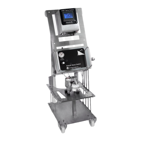
- Page 1 ® AutoJet SCS Series Fluid Delivery System OWNER’S MANUAL ML00SCSFLUID spray.com...
-
Page 2: Table Of Contents
TABLE OF CONTENTS 1. Preface ······················································································································································ 3 1.1 Important ······················································································································································· 3 1.2 How To Use This Manual ······························································································································· 3 2. Safety ······················································································································································· 3 2.1 General Safety Information ··························································································································· 3 2.2 Unpacking The System ··································································································································· 4 3. SCS Series Introduction ······························································································································ 5 3.1 Optional Add-Ons ··········································································································································... -
Page 3: Preface
This manual is intended to be a source of information for the operators and technicians who may be installing, inter- acting with or servicing/maintaining Spraying Systems Co.® systems and components. This manual contains important safety warnings, installation instructions, operating instructions, troubleshooting and maintenance information. -
Page 4: Unpacking The System
USE OF CHEMICAL COMPONENTS Spraying Systems Co. does not manufacture or supply any of the chemical components used in this equipment and is not responsible for their effects. Because of the large number of chemicals that could be used and their different chemical reactions, the buyer and user of this equipment should determine compatibility of the materials used and any of the potential hazards involved. -
Page 5: Scs Series Introduction
SECTION 3 SCS SERIES INTRODUCTION The SCS Series includes many components, some are necessary components with other Spraying Systems Co.® systems and some are add-ons that might work with your current system. These systems and devices are included with the complete package for AutoJet®... -
Page 6: Optional Add-Ons
3.1 OPTIONAL ADD-ONS These add-on systems are for any liquid delivery supply units. ® — ACCUCOAT HD15 IN-LINE HEATER For applications that require heating the HD15 In-Line Heater is an optional add-on for the Coating Supply Unit. The in-line construction allow heating to be achieved only on-demand for optimal response and energy efficiency. For ®... -
Page 7: Spray Control Panel Options
3.2 SPRAY CONTROL PANEL OPTIONS Spray control modules pair with the optional variable spray mount and provides the means to set operating ® parameters and control the functioning of the automatic spray nozzles. AutoJet offers three updated panel models to choose from. -
Page 8: Air Control Panel (Acp)
SECTION 4 AIR CONTROL PANEL (ACP) 4.1 OVERVIEW The Air Control Panel (ACP) provides and regulates the air supply to any nozzles utilizing atomizing and/or fan air and features a precision liquid regulator that allows for smooth and quick pressure adjustments. Easy access push-to- connect tube fitting ports are located on the top and bottom of the ACP. -
Page 9: Acp Configurations
4.3 ACP CONFIGURATIONS The full system versions are equipped with electric valves, manual pressure regulators and gauges to control: • Pneumatic nozzle actuation. • Liquid spray pressure and recirculation rate. • Based on the configuration the system can control atomizing air and fan air. ... -
Page 10: Air Filter/Regulator
It is not regulated; therefore, you must provide a minimum of 45 psi (3.1 bar) to ® the system. It must be above 45 psi (3.1 bar) to actuate air actuated nozzles like Spraying Systems Co. 1/4JAU series. -
Page 11: Pump Version
SECTION 5 PUMP VERSION 5.1 OVERVIEW The pump version features a durable, air operated diaphragm pump that requires liquid to be supplied by a tote or a tank using the system’s pump. The pump is not designed to receive pressurized fluid. This version has an option to re- circulate liquid from the system back to the supply tank. -
Page 12: Priming The Pump
Standard Recirculation Hook-Up Pump Recirculation Inlet IF YOU HAVE PRESSURE SENSOR: Hookup the 1/4” NPTF outlet to the 1/2” NPTF liquid outlet on the pump. Than attach the M12 pressure port cable to the corresponding M12 solenoid cable for cylinder air port on the ACP. See your specified Control Panel Manual for all sensor and cable specifications. - Page 13 • The second method is to utilize a “T” splitter on the liquid outlet line with one leg tied into the fluid return line and back into the needle valve. The “T” splitter can be located anywhere from the pump outlet to the back of the nozzle itself.
-
Page 14: Pumpless Version
SECTION 6 PUMPLESS VERSION 6.1 OVERVIEW The Pumpless Version is the liquid regulator only. It is designed for applications where fluid delivery utilizes a pressurized source typically supplied by the customer. This small assembly ships loose to be mounted directly to the fluid supply. -
Page 15: Pressure Pot
6) Attach the M12 pressure port cable to the corresponding M12 solenoid cable for cylinder air port on the ACP. (See Pumpless- Pressure Sensor Options for more information.) SECTION 7 PRESSURE POT 7.1 OVERVIEW The Pressure Pot Version is designed to pressurize the liquid supply using air over liquid. It only controls the air pressure going to the pressure pot. -
Page 16: Coating Supply Unit-Threaded
SECTION 8 COATING SUPPLY UNIT—THREADED 8.1 OVERVIEW The Coating Supply Unit is designed for applications that require a larger tank size (15 gal/56.8 L) and that may benefit from a higher flow rate system with more automated capabilities with the inclusion of auto-refill. The Coating Supply Unit fluid delivery consists of a diaphragm pump mated to a back-pressure regulator that allows for excess fluid pres- sure to be re-circulated back to the supply tank. -
Page 17: Auto-Refill/Level Sensor
5. If external circulation to the nozzles and back is desired, an orifice plate is provided at the return. 6. Make sure 2-way ball valve on liquid outlet is open and if desired, 2-way ball valve on liquid inlet is open for re- circulation. - Page 18 3. Next, connect fluid line from the refill valve port to the fill port at the bottom of the tank and connect the air supply to the auto-refill panel. AUTO-REFILL CONTROL PANEL SET-UP 1. Connect power to the controller. 2. Plug the level sensor cable into the sensor mounted to the main tank unit.
-
Page 19: Transfer Pump
in the tank will decrease. Once the fluid reaches 250 mm from the bottom of the probe, 63% full (100% * (250- 10)/380=63%), Auto-Refill will turn on. As the fluid level rises and reaches 390 mm from the bottom of the probe, 100% full, Auto-Refill will be turned off. -
Page 20: Troubleshooting
SECTION 9 TROUBLESHOOTING Some faults set the system into standby mode. In this mode, no further triggers are accepted until the reason for the fault has been corrected. Once the fault has been corrected, complete a power cycle of the spray control panel. For some faults the SCS Series spray control panels will recover without intervention, but will still indicate the fault on the fault screen. - Page 21 PUMP VERSION No fluid pressure: — Check air supply to system. Ensure that there is a minimum of 45 psi (3.1 bar) of air pressure on the main air input to the system and that the main air valve is in the “on” position. —...
-
Page 22: Cleaning Procedure
SECTION 10 CLEANING PROCEDURE COATING SUPPLY UNIT- SYSTEM CLEANING PROCEDURE ATTENTION: Cleaning procedure is only a suggestion. Customer is responsible for a sanitation procedure that meets their requirements and standards. 1. If Applicable: Turn the auto-refill switch on the main control panel to the “OFF” position 2. -
Page 23: Suggested Maintenance
SECTION 11 SUGGESTED MAINTENANCE ATTENTION: Any long-term shutdown requires that all liquid lines, liquid components, pumps, and spray guns be flushed and cleaned thoroughly. Daily Monthly Every 6 Months Every 12 Months • • •Check component calibration Pneumatic Check for leaks Tighten all screw •Check system main Controls... - Page 24 Air Control Panel - 070TS07000001W0 Part Number 1750+ SCS, valve assembly, liquid only, purchased assembly 070TS07000001W0_PA01 Cap, M12(f) Connector, for covering M12 male threads JC002774398ND Grommet, for 3/4" Hole Dia., 9/16" ID, 1/16" Material Thickness, 1" Flange Dia., SBR WA009600K21 Rubber, Black cable, mini din ground down to M12 male, SCS Series air supply packages, cylinder WRPCNS000025-00...
- Page 25 Pump Assembly Kit - 070TS07000005W0 Part Number 58685-1/2-PVC PVC PILOT REGULATOR W/VITON 58685-1/2-PVC Strainer, 100 mesh, FDA compliant 1/2 Two-FC100 Screen, 100 mesh stainless , for 1/2TWD-SS100 (and 3/8) Strainer & SCS Series liquid CP5594 -7- 304SS strainer Mounting Foot, Vibration Damping, Natural rubber, 1" OD, 1.0" tall, 304SS mtg. studs, 5/6- MC005823K8 18 thd., 50A durometer, -10 to+150 deg.
- Page 26 Main Air Hook-Up kit - 070TS07000008W0 Part Part Number 1750+ valve kit, inlet valve, filter, pressure gauge, 652 series. 070TS07000008W0_ PA01 Recirculation Standard Kit - 070TS07000022W0 Part Number Stem, Push to Connect, Straight, 1/2" Stem to 3/8" ODT, Acetal Copolymer, Food PLXXPIACADRCID0 Contact Connector, WYE, Push to Connect, 1/2"...
- Page 27 However, Spraying Systems Co. assumes no liability for errors or omissions and reserves the right to make changes without notice to any products described herein to improve reliability, function, or design. Other company and product names may be trademarks of their respective companies.
Need help?
Do you have a question about the AutoJet SCS Series and is the answer not in the manual?
Questions and answers