Table of Contents
Advertisement
Advertisement
Table of Contents

Related Manuals for Spraying Systems Co TeeJet 845


Summary of Contents for Spraying Systems Co TeeJet 845
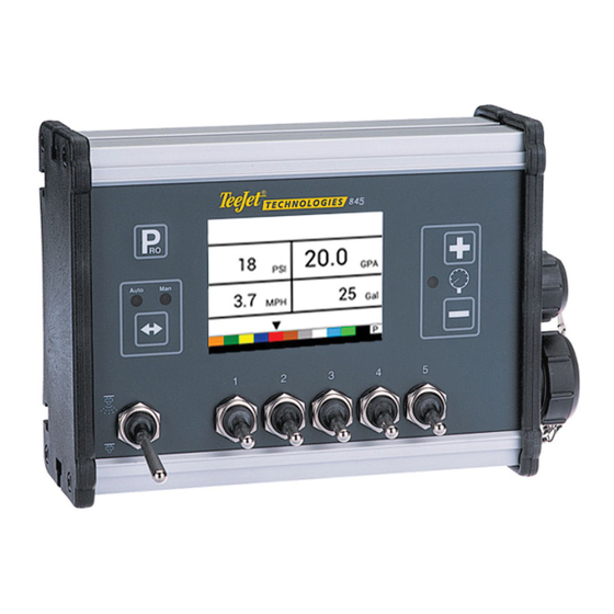
- Page 1 845 SPRAYER ® VOYAGER 570G U S E R M A N U A L U S E R M A N U A L 98-05349 R0...
- Page 2 Copyrights © 2021 TeeJet Technologies. All rights reserved. No part of this document or the computer programmes described in it may be reproduced, copied, photocopied, translated, or reduced in any form or by any means, electronic or machine readable, recording or otherwise, without prior written consent from TeeJet Technologies.
-
Page 3: Table Of Contents
Advance to the Next Option ..................................2 Edit a Setup Option ......................................2 Exit the System Setup Mode ..................................2 CHAPTER 2 – INSTALLATION MOUNTING THE TEEJET 845 CONSOLE Console Step 1 - Location ....................................3 Console Step 2 - Mounting ..................................3 Console Step 3 - Power Connection ................................3 Console Step 4 - Connecting Component Cables ..........................4... - Page 4 ® 845 Sprayer Control System SYSTEM SETUP DETAILS Units ............................................9 Restore Defaults ...............................9 Speed Sensor Calibration ....................................9 Distance Counter ..............................10 Pressure Sensor Installed ..................................10 Zero Pressure Reference ............................10 Maximum Pressure Rating ............................11 Minimum Pressure ...................................... 11 Flow Meter Installed ....................................11 Flow Meter Calibration ............................
- Page 5 845 Sprayer Control System CHAPTER 5 – OPERATING INSTRUCTIONS WORK SCREEN BEFORE YOU GET STARTED Sprayer Check ....................................... 23 THE SPRAYING OPERATION BOOM SECTIONS & SWITCHES OPERATION FEATURES Tank Level ........................................25 View Tank Level ..............................25 Adjust Tank Level ..............................25 Clear Counters ......................................
- Page 6 ® TeeJet Technologies IMPORTANT SAFETY INFORMATION All safety related and operating instructions should be read before the system is operated. Safe operation of machinery is the operators responsibility. Safety procedures must be posted close to the equipment and clearly visible to and legible by the operator. Safety procedures should meet all company and local regulations, as well as MSDS-requirements.
- Page 7 ® TeeJet Technologies WARNING! PRESSURISED HYDRAULIC SYSTEMS • Always wear personal protective equipment (PPE) when performing work on hydraulic systems. • Adhere to the machine manufacture’s approved maintenance instructions when working on the hydraulic system. • Always turn equipment off when working on the hydraulic system. Take appropriate precautions when opening systems that have been previously pressurised.
- Page 8 ® TeeJet Technologies CAUTION! HARNESS CABLE AND HOSE SAFETY • Routinely check all harness cables and hoses for damage or wear. Replace or repair when necessary. • Do not route harness cables and hoses with sharp bends. • Do not strap harness cables and hoses to lines with high vibration or spikes in pressure. •...
-
Page 9: Chapter 1 - Introduction
845 Sprayer Control System CHAPTER 1 – INTRODUCTION Make sure that all hardware components are properly installed and tested. Before starting the programming process, confirm that the console and all sensors are working properly. IMPORTANT! Before beginning, review the following Program Guidelines that control the programming process Regulation Indicator Program button Plus and Minus buttons... -
Page 10: Program Menu Guidelines
845 Sprayer Control System PROGRAM MENU GUIDELINES Enter the Setup Modes Edit a Setup Option For either of the two setup modes, the Master boom switch must Press the PLUS button to increase the value or go to the next be off. -
Page 11: Chapter 2 - Installation
845 console on. If the display shows information, you have wired the power correctly. NOTE: The TeeJet 845 Sprayer Control has an Automatic Power Down feature. With the Master Switch in the “OFF” position, the 845 will automatically shut down after 10 minutes of no inputs or at the time specified in the Auto Power Down setting in the OEM Setup Mode. -
Page 12: Console Step 4 - Connecting Component Cables
845 Sprayer Control System Console Step 4 - Connecting Component Cables Once the console is installed, connecting it to the other components of the 845 system can begin. The standard kit contains a main cable that attaches to the master valve (optional), boom control valves, the pressure regulating valve, flow meter, and/or pressure sensor, and a proximity speed sensor or radar speed sensor. -
Page 13: Connecting The Teejet 845 Console
845 Sprayer Control System CONNECTING THE TEEJET 845 CONSOLE Connect Step 1 - Wiring Layout Determine the best cable routing to the sprayer control components on the sprayer. This may be along the flow line, main frame of the sprayer, or wherever the cables can be conveniently secured. Avoid any situation where the cables may lay in puddles or come in contact with extreme heat sources. -
Page 14: Connect Step 2 - Making The Connection
845 Sprayer Control System Connect Step 2 - Making The Connection Now, extend the cable leads to the Flow meter or Pressure Sensor, and GNSS Speed Sensor to the furthest component. Select the appropriate lead and connect to this component. Run the cable to the other component, taking care to safely secure the cable along the route. - Page 15 845 Sprayer Control System Figure 2-8: Pressure Sensor Connector Pressure Sensor Connector Pin No. Wire Color Signal Name White Power Out Black Pressure Signal Figure 2-9: Flow Sensor Connector Flow Sensor Connector Pin No. Wire Color Signal Name Brown Power Out White Flow Signal Green...
-
Page 16: Chapter 3 - System Setup Mode
845 Sprayer Control System CHAPTER 3 – SYSTEM SETUP MODE PROGRAM MENU GUIDELINES The System Setup Mode contains the programming steps that customize the controller to the sprayer components. These include Enter the System Setup Mode the calibration steps and parameters that seldom change once The Master Switch must be off. -
Page 17: Save All Setting Values
845 Sprayer Control System Save All Setting Values Figure 3-3: Reset Defaults At any time in Setup Mode, press PROGRAM button and PLUS button simultaneously for 3 seconds to enter the Save All Setting Values option. IMPORTANT: This is a safety backup function. Values are always stored when leaving the menu. -
Page 18: Distance Counter
845 Sprayer Control System 3. Start driving toward the start point of the 300 foot / 100 meter Figure 3-6: Distance Counter course. 4. As the starting point is crossed, press the PLUS button once to begin the calibration process. The 845 will count the Pulses generated while the course is driven. -
Page 19: Maximum Pressure Rating
845 Sprayer Control System Automatic Calibration Minimum Pressure Make sure that the sprayer pump is turned off and that there is Below the Minimum Pressure value, regulation is stopped, except when using lane spraying (GLM or LKM). absolutely no pressure in the system (release pressure held by boom control valves and Tip/Nozzle body check valves). - Page 20 845 Sprayer Control System Figure 3-13: Flow Meter Automatic Calibration Figure 3-14: Flow Meter Automatic Calibration Automatic Calibration A volume of at least 50 gallons / 200 liters should be sprayed during the calibration. The more volume used for calibration, the more accurate the flow meter will be.
-
Page 21: Flow Sensor Minimum Flow Capacity
845 Sprayer Control System Flow Sensor Minimum Flow Capacity Regulation Mode This step is only available if “Flow Meter Installed” is set to “Yes” This step is only available when both a Flow Meter and a Pressure Sensor are installed. This step is automatically set to “Flow” and and the console is programmed for use with a pressure sensor. -
Page 22: Number Of Sections
845 Sprayer Control System Number of Sections Figure 3-20: Density Factor This setting is not available if lane spraying is selected (GLM or LKM). Select the number of sections. The number of sections must match the physical number of sections on the sprayer. Figure 3-18: Number of Sections Regulation Valve Type The Regulation Valve Type instructs the console where the... -
Page 23: Regulation Speed Factor
845 Sprayer Control System Regulation Speed Factor Section Valve Type Operating conditions may necessitate a higher or lower response This setting is not available if lane spraying is selected (GLM or LKM). speed for the regulating valve. Any combination of numbers between 0.0 and 9.9 can be selected. -
Page 24: Minimum Tank Level
845 Sprayer Control System Minimum Tank Level GPS Speed The GNSS receiver must be sending the GPVTG string at 19200 Sets the tank level at which an alarm will trigger. Baud or MidTech98 messages at 9600 Baud with a sampling rate Setting this value to 0 will disable the tank alarm. -
Page 25: Use External Rate
845 Sprayer Control System Use External Rate Low Speed This setting is only available if communication mode is set to Set simulated low speed. “MT-98 VR+speed” or “TJ844 Var.Rate”. Figure 3-29: Simulated Ground Speed – Low Speed Variable Rate is used to indicate whether local control rates are to be used or ignored. -
Page 26: Oem Menu
845 Sprayer Control System OEM MENU The OEM menu is normally only used by the OEM manufacturer for setting up machine specific parameters. For assistance with an option in the OEM menu, contact customer service for assistance. OEM options include: ►... -
Page 27: Chapter 4 - Application Setup Mode
845 Sprayer Control System CHAPTER 4 – APPLICATION SETUP MODE The Application Setup Mode is used to set up application specific Edit a Setup Option Press the PLUS button to increase the value or go to the next parameters. option on the list. APPLICATION SETUP OVERVIEW Press the MINUS button to decrease the value or go to the... -
Page 28: Application Setup Details
845 Sprayer Control System Known Speed Calculation APPLICATION SETUP DETAILS This setting is not available if units are set to “NH3” or lane spraying (GLM or LKM). The speed field will be blank. Target Application Rate Set target application rate. The console will calculate what the pressure must be to maintain the target application rate at the entered speed. -
Page 29: Predefined Tip/Nozzle Selection
845 Sprayer Control System Predefined Tip/Nozzle Selection This setting is not available if units are set to “NH3” or lane spraying (GLM or LKM). The Tip/Nozzle indicator will not be available. The console will show the reference flow for the selected Tip/ Nozzle. -
Page 30: Chapter 5 - Operating Instructions
845 Sprayer Control System CHAPTER 5 – OPERATING INSTRUCTIONS WORK SCREEN The work screen is comprised of 6 information areas including: A. Information Bar - Displays icons to show current modes B. Program Mode C. Density Factor active D. Simulated Speed active E. -
Page 31: Before You Get Started
845 Sprayer Control System BEFORE YOU GET STARTED Sprayer Check Before spraying, check all connections related to the Sprayer 7. Now, toggle the Master Switch to “ON.” Control assembly. 8. Adjust the pressure with the PLUS button and/or MINUS WARNING: Whenever working around a sprayer or farm chemicals, button. -
Page 32: The Spraying Operation
845 Sprayer Control System THE SPRAYING OPERATION Upon entering the field at the point where spraying will begin, turn 1. Switch the console on by pressing the PROGRAM button on the display panel. the Master Switch to “ON” position. This will activate the spraying operation. -
Page 33: Operation Features
845 Sprayer Control System button to confirm the selection and OPERATION FEATURES 4. Press the PROGRAM exit to normal work screen. Tank Level Figure 5-4: Clear Counters The tank level menu is used to show and/or set the actual content level in the tank. -
Page 34: Deactivate Simulated Speed
845 Sprayer Control System Deactivate Simulated Speed Figure 5-7: Automatic Regulation Mode Once the sprayer begins moving and the console receives actual speed pulses, simulated ground speed is deactivated. If a Radar/ GNSS Speed Sensor is being used, disconnect the Radar/GNSS from the main console. -
Page 35: Reset Target Application Rate
845 Sprayer Control System Reset Target Application Rate Reset the target value to the set rate. See Target Application Rate in Chapter 4 for details on the set rate. 1. Press the PLUS and MINUS buttons simultaneously. Regulation Indicator The LED indicator shows when the console is regulating upwards or downwards (i.e. -
Page 36: Audible Alarms
845 Sprayer Control System Audible Alarms A number of sensor alarms have been included in the 845 software. The alarm system is only active with Master on. All audible alarm signals can be cancelled by pressing any button. All alarms are reset when Master is switched off. Alarm Name Examples Description... - Page 37 845 Sprayer Control System Alarm Name Examples Description Audible Alarm Type With flow based regulation, the controller (if pressure sensor installed) will compare the Pressure Difference Warning No audible alarm. actual measured pressure with the calculated pressure (based on flow and Tip/Nozzle type). With pressure based regulation, the controller (if flow meter installed) will compare...
-
Page 38: Appendix A - User Setting Notes
845 Sprayer Control System APPENDIX A – USER SETTING NOTES CONFIGURATIONS System Setup OEM Menu Description User Setting Description User Setting Units Minimum Regulation Valve Voltage Restore Defaults Regulation Dead Band Speed Sensor Calibration Regulation Time From Minimum to Maximum Distance Counter PWM Minimum Pressure Sensor Installed... - Page 40 845 SPRAYER U S E R M A N U A L www.teejet.com 98-05349-ENUS A4/LT R0 English © TeeJet Technologies 2021...
Need help?
Do you have a question about the TeeJet 845 and is the answer not in the manual?
Questions and answers