Table of Contents
Advertisement
Quick Links
Advertisement
Table of Contents

Related Manuals for Spraying Systems Co TeeJet 844-E


Summary of Contents for Spraying Systems Co TeeJet 844-E
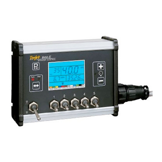
- Page 1 844-E SprayEr Control U S E r M a n U a l Installation, Programming and Operating...
-
Page 2: Table Of Contents
844-E Sprayer Control Table of Contents ChaptEr 1 - introdUCtion ChaptEr 2 - MoUnting SprayEr CoMponEntS Pressure Regulator in Bypass Mode ................................2 Pressure Regulator in Throttling Mode ................................. 3 Flow Meter ..........................................4 Boom Control Valves ......................................4 Pressure Transducer ......................................4 inStalling thE SpEEd SEnSor aSSEMbly Components ....................................5 Speed Step 1 - Location ...................................... - Page 3 844-E Sprayer Control User Program Tip.........................................16 User Programmable Tip ................................16 Pressure Regulation ......................................16 Pressure Regulation Mode ................................16 Regulation Adjustment Speed..................................17 Control Valve Type ......................................17 Boom Control Valve Type: 2-Way/3-Way .............................17 Calibrate Speed ........................................18 Speed Sensor Calibration ................................18 Proximity/Magnetic Pulses ................................18 Automatic Calibration ................................18 Manual Calculation: ................................18 Radar Speed Pulses ......................................18...
- Page 4 844-E Sprayer Control ChaptEr 7 - Flow MEtEr Calibration Method 1 – Known Volume ....................................29 Step 1 – Known Value .................................29 Step 2 – Programming Calibration Number ..........................29 Step 3 – Resetting Volume Counter ............................29 Step 4 – Spraying Known Volume ...............................29 Step 5 –...
-
Page 5: Chapter 1 - Introduction
844-E Sprayer Control ChaptEr 1 - introdUCtion Congratulations! And thank you for choosing TeeJet Technologies’ advanced 844-E sprayer control system. With its proper installation and maintenance, you can enjoy many seasons of accurate and uniform spray application with fingertip convenience and ease of operation. Installation and Programming of your control system will be covered in easy to follow, step-by-step instructions. -
Page 6: Chapter 2 - Mounting Sprayer Components
844-E Sprayer Control ChaptEr 2 - MoUnting SprayEr CoMponEntS pressure regulator in bypass Mode All pressure regulating valves for the 844 will be wired for use in a by- pass system. While plumbed in a by-pass mode, with the Auto/Manual key in the “MAN”... -
Page 7: Pressure Regulator In Throttling Mode
844-E Sprayer Control Figure 2: Bypass Plumbing Diagram - Flow Based System pressure regulator in throttling Mode The pressure regulating valve, as shown in the figures below, can be located in the supply line before the boom control valves. If you choose this location, the 844 will need to be properly programmed to reverse the polarity of the valve. -
Page 8: Flow Meter
844-E Sprayer Control Figure 4: Throttling Plumbing Diagram - Pressure Based System Flow Meter pressure transducer To ensure accurate readings, the flow meter (if used) must be mounted The pressure transducer (if used) should be installed as close to 10″ to 12″ (25-35 cm) from other pipe fittings, preferably in a vertical the spray tips as possible. -
Page 9: Installing The Speed Sensor Assembly
844-E Sprayer Control inStalling thE SpEEd SEnSor aSSEMbly Components Two (2) magnets, Sensor with attached connector cable, and mounting hardware. If you are installing a radar ground speed sensor, follow the instructions supplied with that unit. Speed Step 1 - location The speed sensor assembly should be installed on a non-driven wheel Figure 6: Wheel Mounting of Magnetic Speed Sensor to avoid potential errors that are likely to occur from a slipping drive... -
Page 10: Speed Step 2 - Installing The Wheel Magnets
844-E Sprayer Control Speed Step 2 - installing the wheel Magnets Speed Step 3 - installing the Magnetic Sensor Check for pre-drilled holes in the wheel rim. If pre-drilled holes are not available, layout a pattern as shown in Figure 7 and drill two 3/8″ (10 The flat, pressed L bracket of the wheel speed sensor kit should be mm) holes near the outer edge of the rim if possible, and 180°... -
Page 11: Speed Step 4 - Confirming Speed Sensor Installation
844-E Sprayer Control Speed Step 4 - Confirming Speed Sensor MoUnting thE tEEJEt 844 ConSolE installation Console Step 1 - location Magnetic Wheel Sensor Determine the best location for the control console in the cab or After your wheel or proximity sensor is installed and once the 844 operator’s compartment. -
Page 12: Console Step 3 - Power Connection
844-E Sprayer Control Console Step 3 - power Connection Locate the power cable that has a black connector on one end and two battery terminal rings on the other. Extend the battery terminal ring end of this cable from the cab to the battery. NOTE: Some tractors use two 6 Volt batteries as a power source. -
Page 13: Console Step 4 - Connecting Component Cables
844-E Sprayer Control Console Step 4 - Connecting Component Cables Now that you have the console installed you can begin connecting it to the other components of the 844 system. The standard kit contains a main cable that attaches to the boom control valves, the pressure regulating valve, flow meter and/or pressure sensor, a magnetic wheel speed sensor, and a proximity speed sensor or radar speed sensor. -
Page 14: Connect Step 1 - Wiring Layout
844-E Sprayer Control Connect Step 1 - wiring layout Determine the best cable routing to the sprayer control components on the sprayer. This may be along the flow line, main frame of the sprayer, or wherever the cables can be conveniently secured. Avoid any situation where the cables may lay in puddles, or come in contact with extreme heat sources. -
Page 15: Connect Step 2 - Making The Connection
844-E Sprayer Control Connect Step 2 - Making the Connection Now, extend the cable leads to the Flow meter or Pressure Sensor, and Wheel Sensor or Radar Sensor to the furthest component. Select the appropriate lead and connect to this component. Run the cable to the other component, taking care to safely secure the cable along the route. Refer to the diagram on page 10. - Page 16 844-E Sprayer Control Figure 18: Pressure Sensor Connector Pressure Sensor Connector Pin No. Wire Color Signal Name White Power Out Black Pressure Signal Figure 19: Flow Sensor Connector Flow Sensor Connector Pin No. Wire Color Signal Name Brown Power Out White Flow Signal Green...
-
Page 17: Chapter 3 - Programming
844-E Sprayer Control ChaptEr 3 - prograMMing important preliminary information Steps to Successful programming Before you begin, we recommend that you review the following To begin the programming process: Programming Guidelines that control the programming process: • Read above for programming tips. •... -
Page 18: System Setup Mode
844-E Sprayer Control SyStEM SEtUp ModE Sensor type The System Setup Mode contains the programming steps that customize the controller to the sprayer or sprayer components. These Flow Meter or Pressure Based include calibration steps and parameters that, once programmed, will Default = FLO likely never change. -
Page 19: Pressure Transducer
844-E Sprayer Control pressure transducer nozzle Spacing Default = 20 (inches in US, trF, and INP Modes) Maximum rating (P Hi) Default = 50 (centimeters in Si Mode) Default = 150 (PSI in US, trF and I P Modes) Default = 30 (inches in nh3 Mode) Default = 10. -
Page 20: User Program Tip
844-E Sprayer Control User program tip pressure regulation User Programmable Tip Pressure Regulation Mode Default = 0. 0 0 Default = byp (By-pass for US, trF, I P, and Si Modes) While in the User Programmable Tip step, the tip indicator arrow Default = thr (Throttling for nh3 Mode) will be flashing above the tab at the bottom of the display. -
Page 21: Regulation Adjustment Speed
844-E Sprayer Control regulation adjustment Speed Control Valve type Default = 9. 5 (byp Mode) Boom Control Valve Type: 2-Way/3-Way Default = 2 Way While in this step, the regulator symbol will be flashing at the top of the console display. This step allows you to regulate the speed of the While in this step, the regulator symbol will be flashing at the top pressure regulating valve to accommodate different application needs. -
Page 22: Calibrate Speed
844-E Sprayer Control Calibrate Speed Speed Sensor Calibration Default = 250 NOTE: During Speed Calibration, the 844 will automatically sense whether a Wheel Speed or Radar Speed Sensor is being used. While in the Speed Calibration Programming Step, the calibrate speed symbol will be flashing at the top of the display. -
Page 23: Distance Counter
844-E Sprayer Control distance Counter program Specific gravity Default = 0 Liquid Specific Gravity (Density) This step is a feature, not a calibration step. No specific value needs to Default = 1. 0 0 be entered here for the controller to operate correctly. While in the Liquid Specific Gravity (Density) Programming Step, the This feature will measure distance in feet (meters). -
Page 24: Communications
(target application rate, and nozzles This step lets you select what type of communication you will be used). Spraying Systems Co. has added this separate setup mode using. The choices available are the default of “no CO ”... -
Page 25: Nozzle Selection
844-E Sprayer Control nozzle Selection Default = Red or 0.4 US gPM (1.29 l/min) {0.33 Imperial gPM} While in the nozzle selection step, the display will remain the same as in the Target Application Rate step except the indicator arrow will be flashing at the bottom of the display just above a color coded strip. -
Page 26: Calculation Troubleshooting
844-E Sprayer Control Calculation troubleshooting NOTE: If you are going to be spraying with a different density of liquid This Programming Step is a diagnostic tool only other than water and you have programmed that specific This programming step has no effect on the operation of the TeeJet gravity (density) into the Specific gravity (Density) Step in the 844 Sprayer Control. -
Page 27: Chapter 4 - Operating Instructions
844-E Sprayer Control ChaptEr 4 - opErating inStrUCtionS Sprayer Checkout the Spraying operation Before spraying, check all connections related to the Sprayer Control You have filled the sprayer tank and have thoroughly mixed the assembly. Particular attention should be given to the speed sensor to chemical(s).Your application rate has been determined as well as the be sure the sensor and magnets are in line, and properly secured. -
Page 28: Chapter 5 - Features
844-E Sprayer Control ChaptEr 5 - FEatUrES boost Mode To clear the area counter/volume measure, press and hold the Plus and Minus key simultaneously for three (3) seconds while There may be instances where ”on the go” increased or decreased viewing the normal operating mode. -
Page 29: Printing
844-E Sprayer Control printing Optional printers are available for printing a spraying report directly from the 844. The optional printers are available through your TeeJet supplier. The printout that you get from the 844 contains memory information that the 844 collects. A sample of this printout is below. To set the 844 for printing, advance to the last step of the System Setup mode and select “Prt”... -
Page 30: Chapter 6 - Troubleshooting Guide
844-E Sprayer Control ChaptEr 6 - troUblEShooting gUidE Condition Possible Cause Solution 1. Application Rate Units (GPA, G/1000 A. Continuous discrepancy of 10% or Check all components and programming steps related to flow I/Ha) continually flash on/off more between Target Application Rate and Actual Application Rate prograMMing In the System Setup mode, move to the Flow Meter Pulses section on page 14 of the... - Page 31 844-E Sprayer Control Condition Possible Cause Solution A. Stalled Flow meter Make sure there is no pressure in the system. Flow meter turbine symbol continually flashes on/off Remove the flow meter from the discharge line. Inspect the inside of the meter for obstructions.
- Page 32 844-E Sprayer Control Condition Possible Cause Solution 6. Application Rate Units (GPA, G/1000 A. Speed sensor not calibrated Recalibrate the magnetic or radar speed pulses in the Calibrate Speed section of the I/Ha) continually flash on/off correctly System Setup Mode on page 18 of the 844 Installation Manual B.
- Page 33 844-E Sprayer Control ChaptEr 7 - Flow MEtEr Calibration The flow meter supplied with your system has been calibrated at the factory and under normal circumstances there may be no need to re-calibrate it. However, the factory calibration setup may not reflect specific sprayer plumbing. Before spraying actual chemicals, the flow meter should be checked for proper calibration.
- Page 34 844-E Sprayer Control Step 4 – Measure Turn controller on and activate pump. Toggle on the Master Boom Switch and the number of boom sections to be measured. Insure that the pressure at the boom is maintained at 40 psi (2 bar). While spraying press and hold the Program key in.
- Page 36 844-E sprayEr control U s E r M a n U a l • Full-featured sprayer control with industry-leading ease of use • Large back-lit display shows all spraying information at a glance • Color-coded tip selection for easy programming •...
Need help?
Do you have a question about the TeeJet 844-E and is the answer not in the manual?
Questions and answers