Advertisement
Quick Links
EX510-TF2Z142EN
ORIGINAL INSTRUCTIONS
Instruction Manual
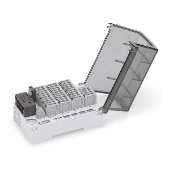
Fieldbus system - Output unit
EX510-DY#3 / -DY#4
The intended use of this product is to provide outputs to control
pneumatic valves and I/O while connected to an SI or Gateway unit.
1 Safety Instructions
These safety instructions are intended to prevent hazardous situations
and/or equipment damage. These instructions indicate the level of
potential hazard with the labels of "Caution," "Warning" or "Danger."
They are all important notes for safety and must be followed in addition
*1)
to International Standards (ISO/IEC)
, and other safety regulations.
*1)
ISO 4414: Pneumatic fluid power - General rules relating to systems.
ISO 4413: Hydraulic fluid power - General rules relating to systems.
IEC 60204-1: Safety of machinery - Electrical equipment of machines.
(Part 1: General requirements)
ISO 10218-1: Manipulating industrial robots -Safety. etc.
• Refer to product catalogue, Operation Manual and Handling
Precautions for SMC Products for additional information.
• Keep this manual in a safe place for future reference.
Caution indicates a hazard with a low level of risk which, if
Caution
not avoided, could result in minor or moderate injury.
Warning indicates a hazard with a medium level of risk
Warning
which, if not avoided, could result in death or serious injury.
Danger indicates a hazard with a high level of risk which, if
Danger
not avoided, will result in death or serious injury.
Warning
• Always ensure compliance with relevant safety laws and
standards.
• All work must be carried out in a safe manner by a qualified person in
compliance with applicable national regulations.
• Refer to the operation manual on the SMC website (URL:
https://www.smcworld.com) for further Safety Instructions.
2 Specifications
2.1 General specifications
Item
Specifications
Enclosure rating
IP20
500 VAC for 1 minute
Withstand voltage
(between FG and terminal block)
10 MΩ or more 500 VDC
Insulation resistance
(between FG and terminal block)
o
Operating: -10 to +50
C
Ambient temperature
Storage: -20 to +60
o
C
Ambient humidity
35 to 85% RH (no condensation)
Operating atmosphere
No corrosive gas
Weight
130 g (including accessories)
2 Specifications (continued)
2.2 Output unit specifications
Item
Specification
EX510-
EX510-
EX510-
Model
DYN3
DYP3
DYN4
PNP /
NPN / sink
NPN / sink
source
Output type
(positive
(positive
(negative
(negative
common)
common)
common)
common)
Number of outputs
16 outputs
Rated Load
24 VDC
Voltage
External power supply
Internal power supply
Power supply type
(from power supply
(from GW unit)
connector)
Power supply
0.14 to 1.5 mm
-
connector wire size
(AWG26 to 16)
Output connector
Cage clamp type (WAGO 739-304 / 310)
Output wire size
0.08 to 1.5 mm
2
(AWG28 to 16)
To meet the following 3
To meet the following
conditions:
3 conditions:
1) 1 output: 0.5 A max.
1) 1 output: 0.5 A max.
Maximum Load
2) 1 unit: 1 A max.
2) 1 unit: 3 A max.
current
3) Total current of
3) Total current of
OUT0 - 7: 1 A max.
OUT0 - 7: 1.5 A max.
OUT8 - 15: 1 A max.
OUT8 - 15: 1.5 A max.
Protection
Short circuit protection
Current
50 mA max. (output unit circuit)
consumption
3 Name and function of parts
Top view
(with cover removed)
No
Part
Description
1
Branch connector
Connection for branch cable to GW unit.
2
Output terminals
Connection for output loads.
LED ON: Power ON (normal)
3
Power supply LED
LED OFF: Power OFF
LED ON: Receiving data
4
Communication LED
LED OFF: No data received
LED ON: Output signal ON
5
Display LED
LED OFF: Output signal OFF
6
Fuse
Replaceable fuse.
7
Mounting slot
Used for mounting on DIN rail.
8
Mounting hole
Used for direct mounting with M4 screws.
Cover to protect cables and provide label
9
Cover
marking.
Power supply
Connection for external power supply
10
terminals
(EX510-DYN4, -DYP4).
11
Branch connector
Connector for branch cable (2 pcs.)
12
Marker plate
Label marking for output details.
4 Installation
4.1 Installation
Warning
EX510-
Do not install the product unless the safety instructions have been read
DYP4
and understood.
PNP /
• Direct mounting
source
Install the output unit using 2 x M4 screws.
Tightening torque: 0.8 N•m.
2
• DIN rail mounting
To mount the product hook claw 1 under the lower side and claw 2
over the upper side of the DIN rail. Press down until it clicks.
To remove from the DIN rail, push up the DIN rail fixing plate with a
flat blade screwdriver, and remove by tilting claw 2 forward.
DIN rail
fixing plate
4.2 Environment
Warning
• Do not use in an environment where corrosive gases, chemicals, salt
water or steam are present.
• Do not use in an explosive atmosphere.
• Do not expose to direct sunlight. Use a suitable protective cover.
• Do not install in a location subject to vibration or impact in excess of
the product specifications.
• Do not mount in a location exposed to radiant heat that would result
in temperatures in excess of the product specifications.
5 Wiring
5.1 Branch cable wiring
The wiring between the Output unit and GW unit uses a branch cable
(EX510-FC##) and branch connector (EX510-LC1). The Output unit has
2 branch connectors.
5.1.1 Pressure welding the branch connector
The pressure welding assembly method of the branch connector is
described below.
• Components
Insulating cap
Pin number
Cover
Body
Branch Connector
Branch Cable (EX510-FC##)
• Assembly procedure
1) Set a branch cable into the cover with the Brown wire to pin #1.
2) Push the cable end up to the insulating cap on the cover.
3) Fold the cover so that the branch cable is trapped between the cover.
4) Fix the latch tip by inserting it through the fixing latch hole.
Hole for
Latch
fixing latch
Pin #1
Brown wire
5) Check that the wire colour marked on the branch connector is the
same as the branch cable wire colour.
• Cable clamping
1) Tentatively fix the Body. Fit the 4 latches on the body to the 4
ditches in the cover and press them until the latch engages.
2) Press fit the cover to the body using suitable pliers.
3) Check that all of the 4 latches are fully engaged.
Page 1 of 2
Advertisement

Related Manuals for SMC Networks EX510-DY 3 Series


Summary of Contents for SMC Networks EX510-DY 3 Series
- Page 1 EX510-TF2Z142EN 2 Specifications (continued) 4 Installation 5 Wiring ORIGINAL INSTRUCTIONS 2.2 Output unit specifications 4.1 Installation 5.1 Branch cable wiring The wiring between the Output unit and GW unit uses a branch cable Warning Item Specification (EX510-FC##) and branch connector (EX510-LC1). The Output unit has Instruction Manual EX510- EX510-...
- Page 2 EX510-TF2Z142EN 5 Wiring (continued) 5 Wiring (continued) 5 Wiring (continued) 10 Maintenance 5.2 Internal Circuit and Wiring 5.2.3 EX510-DYP3: PNP output (internal GW power supply) 5.3 Connection of Branch cable and Output wiring 10.1 General Maintenance 1) Insert the branch cable into the socket on the Output unit. Caution 5.2.1 EX510-DYN3: NPN output (internal GW power supply) 2) Insert the output wiring after removing the cover as follows:...
Need help?
Do you have a question about the EX510-DY 3 Series and is the answer not in the manual?
Questions and answers