Telguard TG-7 Cellular Series Installation & Operating Manual
Hide thumbs
Also See for TG-7 Cellular Series:
- Installation and operating manual (35 pages) ,
- Quick installation manual (4 pages) ,
- Installation and operating manual (31 pages)
Table of Contents
Advertisement
Telguard TG-7 Cellular Series
Installation & Operating Guide
for models TG-7, TG-7FS, TG-7A, and TG-7UB
COMPANY CONFIDENTIAL
For use by TELGUARD
®
customers only.
Distribution to other parties strictly prohibited.
January 3, 2022
Part Number 56053501
Rev A
© 2022 Telguard. Telguard and the Telguard Logo are registered trademarks of
Telular Corporation | Telular is a business unit of AMETEK, Inc. All Rights Reserved.
Advertisement
Table of Contents
Troubleshooting

Related Manuals for Telguard TG-7 Cellular Series


Summary of Contents for Telguard TG-7 Cellular Series
- Page 1 Distribution to other parties strictly prohibited. January 3, 2022 Part Number 56053501 Rev A © 2022 Telguard. Telguard and the Telguard Logo are registered trademarks of Telular Corporation | Telular is a business unit of AMETEK, Inc. All Rights Reserved.
- Page 2 However, Telguard assumes no responsibility for inaccuracies and reserves the right to modify and revise this manual without notice. It is our goal at Telguard to always supply accurate and reliable documentation. If a discrepancy is found in this documentation, please send an email message to: CustomerService.Telular@ametek.com...
-
Page 3: Repair And Warranty
Communicator. Repair of this equipment should only be referred to qualified technical personnel. Telguard will repair or replace (our option) inoperative units for up to two years from date of manufacture. This excludes damage due to lightning or to installer error. Unauthorized modifications void this warranty. -
Page 4: Indemnification Of Telguard
INDEMNIFICATION OF TELGUARD YOU SHALL INDEMNIFY, DEFEND AND HOLD HARMLESS TELGUARD FOR ANY OF THE COST, R, YOUR IN A MANNER NOT CONTEMPLATED BY YOU AND TELGUARD OR INCONSISTENT WITH THE PROVISIONS OF THIS MANUAL; (ii) IN AN ILLEGAL MANNER OR AGAINST PUBLIC POLICY; (iii) IN A MANNER SPECIFICALLY UNAUTHORIZED IN THIS MANUAL;... -
Page 5: Table Of Contents
Foreword Technical Support About this Manual Repair and Warranty Future Testing and Limitations on Use Terms and Conditions for Use of Telguard Product INDEMNIFICATION OF TELGUARD WARRANTY and LIMITATIONS General Description and Operation Information Related to Software Settings Fire Systems... - Page 6 Detailed Specifications Dialer to Interface Electronics Power Requirements Field Wiring Electrical Ratings Power Limited Circuits System Faults Impedance Digital Cellular Radio and Other Specifications Appendix 7 Accessories TG-7 Cellular Series Installation & Operating Guide 56053501 Rev A © 2022 Telguard...
-
Page 7: General Description And Operation
Back-up path (Telco Primary & Cellular Backup) Depending on the TG-7 Cellular Series model and configuration (as set in the dealer portal), the alarm panel will utilize the cellular network as a sole, primary or back-up (secondary) transmission path to deliver alarm messages. - Page 8 The UL Listed equipment at the TCC plays a key role in the operation of every Telguard device. All Telguard units utilize the TCC due to the panel alarm signal format encoding and decoding requirements used in packet-data transmissions over the digital cellular network. The TCC also...
-
Page 9: Information Related To Software Settings Fire Systems
10- 20-, 30-, 45-, 60-, 1440- 3 minutes minutes 6 hours is specified in 2013 and later editions of NFPA 72; the 2010 edition specified 24 hours (daily). TG-7 Cellular Series Installation & Operating Guide 56053501 Rev A © 2022 Telguard... - Page 10 3-, 5- 10-, 20-, 30-, 45-, 60-, 1440- minutes AC Failure Condition (ACFC)/ Disabled, any number of 1 hour, 2 hours, 3 hours Low Power Failure (LPF) hours up to 24 TG-7 Cellular Series Installation & Operating Guide 56053501 Rev A © 2022 Telguard...
-
Page 11: Information Related To Software Settings Burglary Systems
Standard for Central-Station Burglar-Alarm Units, UL 1610 and Standard Line Supervision, the communicator must meet these requirements: The TG-7 Cellular Series communicator must be used in one of the following configurations: • As a primary communicator, single line-200 second supervision; or •... - Page 12 Standard for Control Units, Accessories and Receiving Equipment for Intrusion Alarm Systems, ULC-S304, the communicator must meet these requirements (Security Level I or II): The TG-7 Cellular Series communicator must be used as a Passive communication system line security level P1 (single communication channel) for Security Level I.
-
Page 13: Features
This section summarizes the key features of Telguard TG-7 Cellular Series communicators. Operating Mode The TG-7 Cellular Series is comprised of transmission devices that are installed at protected premises to provide signal transmission over a cellular connection for alarm systems. The communicator transmits alarm signals over the nationwide digital cellular network if the telephone line has been disrupted or compromised, or when set for primary or sole path use of the cellular pathway. -
Page 14: Link Supervision And Standard Line Security
(UL 864, ULC-S559), PPF is not required for fire systems. Control Failure to Communicate (CFC) The Control Failure to Communicate (CFC) feature allows the Telguard unit to monitor the number of communication attempts the alarm panel makes over Telco before the unit becomes the main path of communication. -
Page 15: Complete Power Supervision
(voltage supplied unexpectedly drops). The STC LED will flash 6 times and the STC relay will trip. NOTE: This condition will require contacting Telguard Technical Support for resolution. Catastrophic Failure (CF) Catastrophic Failure (CF) is any condition that causes the communicator to stop functioning at all levels. -
Page 16: Programmable Supervisory Trip Output (Stc) Relays
Check Status causes the communicator to upload current operational status data and historical data, just as the automatic self-test described above, except that the resulting status is held in the Telguard database at the TCC for review and is not forwarded to the Central Station. -
Page 17: Post-Installation Remote Programming
Optional DC Operation (12VDC or 24VDC) The TG-7 Cellular Series communicators can be operated solely by DC power provided by an alarm panel. This eliminates the need for a separate AC outlet at the protected premises. To use, connect 12VDC or 24VDC regulated power from the p communicator. -
Page 18: Ul And Ulc Compliance
UL and ULC Compliance The TG-7 Cellular Series communicators are certified as complying with UL and ULC Standards for Commercial Fire and Commercial Burglary installations. The chart on Page 1 shows the associated UL and ULC Standards. Certificates of Compliance are available at telguard.com. -
Page 19: Getting Ready
TCC customer database (i.e., the unit has been registered). The database includes information about the customer account, unit location, and system test plan information. Dealer Account Establishment A Dealer Account must be established prior to registration of any Telguard unit. This can be accomplished by visiting telguard.com... -
Page 20: Pcb Layout
NOTE: The communicator registration must be completed in advance to avoid installation delays PCB Layout RESET BUTTON RJ-45 RSSI DACT JACK BUTTON for PANEL CONNECTION RJ-45 PHONE JACK for TELCO CONNECTION EARTH GROUND TG-7 Cellular Series Installation & Operating Guide 56053501 Rev A © 2022 Telguard... -
Page 21: Installation
The registration form may be completed online in the 24/7 dealer portal at www.telguard.com. Register for Telguard service prior to going to the job site to avoid a second trip. The desired features and programmable options for any installation are selected during the registration process. -
Page 22: Ul/Ulc Commercial Fire Sole Path (Cellular Only Mode) Features
The message that is sent from the TCC to the Central Station is configurable in www.Telguard.com. The communicator will automatically be configured with a unit template that allows configuration of the trip input feature, including the message that is sent to the Central Station. -
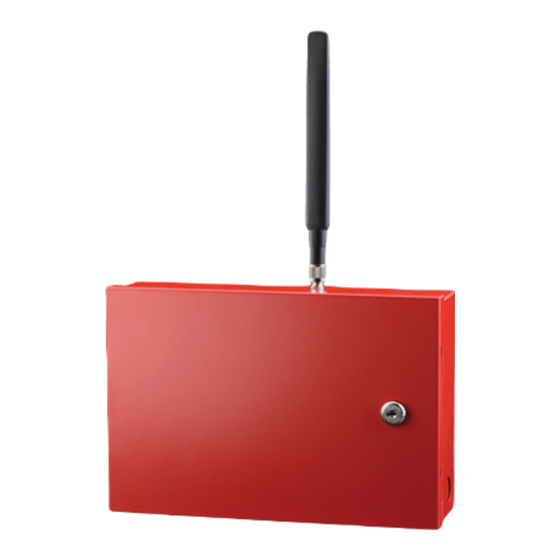
Page 23: Step 2: Physically Install The Communicator In Desired Location
Verify unit is secured by placing additional screws in lower mounting holes. Install Optional TG-PEM Accessory into Enclosure (if using) The TG-PEM Accessory can be used to add 8 24-hour dry contact zones to a TG-7 Cellular Series communicator. The TG-PEM Accessory should be installed after the communicator has been mounted to the wall or other surface. -
Page 24: Step 3: Determine Antenna Placement For Best Performance
NOTE: It is important to fol including replacing the battery when it can no longer operate at the specified voltage level. Connect the Telguard AC power adapter (supplied) to AC terminals using stranded copper insulated wire following wire gauge and length recommendations below:... -
Page 25: Optimizing Antenna Performance
If LED 1 and LED 4 are flashing, the communicator has failed activation. Most likely, the serial number is not in the database at the TCC. Clear the fault (see note below) and call Telguard Technical Support to verify proper registration before resending an alarm signal. -
Page 26: Verify Alarm Signal Transmissions Over Cellular Path
POWER LED 8 goes out and the STC LED 2 flashes once indicating that AC power is missing. Reconnect AC adapter and check to see that the AC POWER LED 8 goes on and the STC LED 2 TG-7 Cellular Series Installation & Operating Guide 56053501 Rev A ©... -
Page 27: Step 6: Connect Tamper Switch (Required For Burg/Optional In Fire-Only Systems)
The TG-7 and TG-7A require a tamper switch be connected (easy-attach assembly included); it is optional on the TG-7FS. Telguard produces the tamper switch as an accessory (listed in Appendix 7) that can be used when needed for communicators not generally requiring the switch. Note that the tamper switch will not connect to the circuit board of the communicator. - Page 28 Bosch P110BL, Bosch EOL-22K, Elk ELR 22). The trip input circuit is not supervised for ground conditions. UL/ULC Compliance Note: The trip input feature shall only be used for supplementary signaling. Initiating zones shall not be connected to the trip input. TG-7 Cellular Series Installation & Operating Guide 56053501 Rev A © 2022 Telguard...
-
Page 29: Appendix 1 Connection Guide
U.S. and Canada (unless noted). Telco Connection through the Communicator (Backup or Primary Mode): Used when the TG-7 Cellular Series communicator is working in a system that involves a Telco connection. In this case, the Telco is connected through the communicator. The communicator monitors the Telco and cellular connection and controls which communication path is used for signal delivery. -
Page 30: Cellular-Only Wiring (When Communicator Is Only Path Used)
DC Power (from Panel). FACP LED1 Battery LED2 LED3 LED4 LED5 LED6 LED7 LED8 NOTE 2 NOTE 1 NOTE 1 Plug-in Adapter TRIP INPUT EARTH GROUND TG-7 Cellular Series Installation & Operating Guide 56053501 Rev A © 2022 Telguard... -
Page 31: Cellular-Only Wiring (With Telco Connection Through Second Panel Dact)
This configuration is used when the communicator is working in a system that also involves a Telco connection or another communication path not connected through the Telguard communicator (generally limited to fire systems). In this case, both the communicator and the alternate connections are being monitored by the alarm panel. - Page 32 6 IN. FRONT VIEW SIDE VIEW LISTED PULL BOX WITH LISTED OUTLET BOX AND RECEPTACLE LISTED PULL BOX WALL LISTED TRANSFORMER LISTED OUTLET BOX AND RECEPTACLE ULTPDE.VSD TG-7 Cellular Series Installation & Operating Guide 56053501 Rev A © 2022 Telguard...
-
Page 33: Tamper Switch Installation
If a tamper switch is needed for a TG-7FS or TG-7UB product, the TG-TAMPER Accessory can be purchased from most Telguard distributors. Note that a tamper switch is required when using the TG-7FS in a combination fire and burglary system. -
Page 34: Rj-45 Jack Pin Assignments
Normally Open. 5 GND Trip Ground and External trip Allows an external relay to LED 7 6 IN Trip Input relay. trigger an alarm signal. TG-7 Cellular Series Installation & Operating Guide 56053501 Rev A © 2022 Telguard... -
Page 35: Ac Terminal Strip Pin Assignments
10 digits for Contact ID, 4 digits for Modem). UL Compliance Note: While TG-7 Cellular Series communicators support the above formats, some formats may not meet the requirements for fire systems set in UL 864. Contact ID and SIA2 are the only formats identified as complying beginning with UL 864 10 Edition. -
Page 36: Appendix 2 Troubleshooting Guide
Operating from communicator backup battery LED 8 activity) Power Solid On Panel power or AC power connected to unit NOTE: * indicates that the LED will continuously flash. TG-7 Cellular Series Installation & Operating Guide 56053501 Rev A © 2022 Telguard... -
Page 37: Troubleshooting Quick Reference Table
(Initiated by TCC) (Status data) signals from the TCC. * If several trouble conditions are present, the STC LED will flash all applicable indications in sequence. TG-7 Cellular Series Installation & Operating Guide 56053501 Rev A © 2022 Telguard... -
Page 38: Led Indicator Guide Rssi Mode
LEDs 5-3 = on, LED 2 = slow flash -60 LEDs 5-2 = on NOTE: When LED 1 is on in RSSI mode, it indicates more than one cellular tower is within range. TG-7 Cellular Series Installation & Operating Guide 56053501 Rev A © 2022 Telguard... -
Page 39: Appendix 3 Commercial Fire Single Dact Installation
Fire panels are typically provided with two Telco connections in order to provide multiple reporting paths. With the TG-7 Cellular Series communicators having a single RJ-45 jack for connecting to the panel, one of these DACT connections is not necessary for UL 864 and ULC-S559 compliance. -
Page 40: Appendix 4 Commercial Fire 6-Hour Supervision
6 hours, from an earlier version of 24 hours. This requirement is upheld in 2016 and 2019 edition as well. Telguard commercial fire products support this feature, and it must be enabled by selecting 6-hour supervision during registration. -
Page 41: Appendix 6 Detailed Specifications
Appendix 6 Detailed Specifications Dialer to Interface Electronics The integrated interface by Telguard allows digital dialers to dial into the cellular radio network. • Line voltage: -30 VDC (default) or -40VDC (option) into standard telephone device when on-hook. • Dial tone: Precision 350 + 440Hz +/- 1%. 10 digits dial out capability. -
Page 42: Appendix 7 Accessories
Description TG-PEM Adds 8 dry contact zone inputs; also allows connection to panels without DACTs TG-TAMPER Easy-attach Tamper Switch Assembly compatible with Telguard metal enclosures ACD-12 12 feet of antenna cable and mounting bracket ACD-35 35 feet of low loss high performance antenna cable and mounting bracket...
Need help?
Do you have a question about the TG-7 Cellular Series and is the answer not in the manual?
Questions and answers