Telguard TG-1 Installation And Operating Instructions Manual
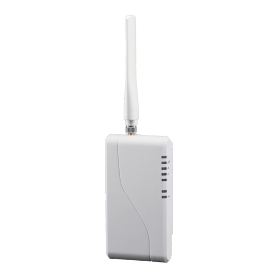
Residential primary cellular alarm communicator
Hide thumbs
Also See for TG-1:
- Installation manual (38 pages) ,
- Quick install manual (13 pages) ,
- Quick install manual (2 pages)
Table of Contents
Advertisement
Quick Links
Advertisement
Table of Contents
Troubleshooting

Related Manuals for Telguard TG-1


Summary of Contents for Telguard TG-1
- Page 1 ® TELGUARD DIGITAL TG-1 ESIDENTIAL RIMARY ELLULAR LARM OMMUNICATOR NSTALLATION AND PERATING NSTRUCTIONS COMPANY CONFIDENTIAL ® For use by TELGUARD customers only. Distribution to other parties strictly prohibited. August 17, 2017...
- Page 2 Dealers purchase Telguard cellular communicators for the quality, features and total value they represent. The Telguard TG-1 model (part #s TG1LA002B) is UL Listed for Household Burglary systems, Household Fire systems, Commercial Burglary and depending on the model, Commercial Fire systems. The Telguard TG-1 model may be used in Household Burglary systems, Household Fire systems or combined Household Burglary &...
- Page 3 Note: RMA number must be on the outside of box or product will not be accepted. Future Testing and Limitations on Use The Telguard TG-1 is part of an advanced design alarm communication system. It does not offer guaranteed protection against burglary and fire.
- Page 4 CLIENTS’ OR OTHER THIRD PARTIES’ USE OR OPERATION OF THE PRODUCT: (i) FOR MISUSE OR IN A MANNER NOT CONTEMPLATED BY YOU AND TELGUARD OR INCONSISTENT WITH THE PROVISIONS OF THIS MANUAL; (ii) IN AN ILLEGAL MANNER OR AGAINST PUBLIC POLICY;...
-
Page 5: Table Of Contents
Dealer Account Establishment Pre-Installation Checklist Installation Summary Step 1: Register the Telguard Unit Step 2: Locate Unit and Measure Signal Strength (RSSI) Step 3: Program, Activate & Transmit Alarms over Cellular Network Step 4: Connect Supervisory Trip Outputs Step 5: Connect and Test the Trip Input (optional) - Page 6 LED Indicator Guide – Normal Operating Mode LED Indicator Guide – RSSI Mode Troubleshooting Quick Reference Table Appendix 3 – Detailed Specifications Dialer to Interface Electronics Power Digital Cellular Radio Appendix 4 – Accessories 56050801 - Rev B © 2017 Telguard...
-
Page 7: General Description And Operation
After decoding and reformatting, the alarm signal is routed to the appropriate alarm company monitoring station for action. In a typical alarm installation, the Telguard is installed in the same area as the Household alarm panel and is connected directly to the Household alarm panel via Telguard's RJ-45 jack. -
Page 8: Features
If the alarm panel’s format is changed for whatever reason, the Telguard will adjust to accept the new format. In order for the alarm panel to be compatible with the Telguard, the alarm panel must be programmed to transmit alarm messages to the central station using one of the following non-extended formats: ... -
Page 9: Complete Power Supervision
(106 VAC), the AC Power LED turns on immediately and the STC trip output restores after 60 seconds. Note: If the Telguard is being powered through its DC connection, a Low Power Failure (LPF) will occur if the DC power drops below 5.1VDC and restore after reaching >5.6VDC. -
Page 10: Telguard Automatic Self-Test Report
Trips on transmit-disable command from the TCC. This radio command disables only the Telguard transmitter and would be used, for example, to shut down the Telguard unit due to a runaway dialer. Diagnostic and Status LEDs Six active LEDs are provided as a useful aid during installation and give installers an immediate visual indication of system status. -
Page 11: Optional Dc Operation (12Vdc)
Telguard and the Telguard will operate normally. The Telguard‘s operational range is 6.2V - 16V DC. Note: When using DC power, the Telguard should not be connected to a battery or AC power source. Because there is no AC connection, the AC LED will be OFF when operating in DC mode. -
Page 12: Getting Ready
Dealer Account has been established. Pre-Installation Checklist Before attempting to connect the Telguard to the alarm panel, please make sure you have all the proper parts before you go to the job site. The following items are shipped with each Telguard: ... -
Page 13: Installation
Installation (see Section 3). Step 1: Register the Telguard Unit Installation Tip: Register for Telguard service prior to leaving for the job site to avoid a second trip. The registration form may be completed online through our 24/7 dealer portal www.telguard.com. -
Page 14: Step 2: Locate Unit And Measure Signal Strength (Rssi)
60 ft Option 2: DC Power To apply DC power to Telguard from a host alarm panel, connect the panel power and ground connections into the respective DC and GND connections on the Telguard. When using this option, no other power connections (battery or AC) should be wired. - Page 15 Do not install the Telguard in an area where the general public could reasonably be within 20cm (8 inches) of the antenna. NOTE 1: Optimum RF performance can usually be found at the highest point within a building with the fewest number of walls between the Telguard unit’s antenna and the outside of the premises.
-
Page 16: Step 3: Program, Activate & Transmit Alarms Over Cellular Network
If the Telguard fails the activation process, it will be displayed on the LEDs. If LED 1 and LED 4 are flashing, the Telguard has failed activation. The serial number is not in the database at the TCC. Clear the fault (see note below) and call Telguard Technical Support to verify proper registration before resending an alarm signal. -
Page 17: Step 4: Connect Supervisory Trip Outputs
Use a lineman's butt-set in MONITOR MODE connected to Telguard's "T" and "R" test pins to "listen" to communications between the alarm panel and the Telguard. If you are having problems getting reliable alarm signal transmissions, additional adjustments may be necessary. -
Page 18: Step 5: Connect And Test The Trip Input (Optional)
When the trip input functionality is being used, closing the trip contact will cause the Telguard to send a message to the TCC, which in turn will cause the TCC to send a message to the central station. If the Telguard is configured to report restorals, the contact opening will also be reported. -
Page 19: Appendix 1 - Connection Guide
RADIO COMMUNICATING 1 2 3 NOT USED NOT USED BATTERY (12V 800MA) TRIP INPUT AC CONNECTED TO UNIT POWER LED AC NOT CONNECTED TO UNIT OPTIONAL STC2 STC1 TRIP BATTERY (N.O.) GND IN (N.C) 56050801 - Rev B © 2017 Telguard... -
Page 20: Jack Assignments
AC Power LED ON when AC is normal. input. un-switched operational power 2 AC AC power LED OFF circuit. to the Telguard 12 VAC and battery 10VA. charging circuit. STC LED 2 Flashes 1 time when AC is low. 56050801 - Rev B... -
Page 21: Compatible Alarm Panels
Compatible Alarm Panels Any UL Listed alarm panel that supports one of the following formats is compatible and may be used with the Telguard: Pulse Formats: 3+1 pulse; 10pps, Double Round, 1400 Hz ack 3+1 pulse; 20pps, Double Round, 2300 Hz ack 3+1 pulse;... -
Page 22: Appendix 2 - Troubleshooting Guide
Appendix 2 – Troubleshooting Guide This section provides a summary of all LED indications and their meanings, as well as the expected behavior of the Telguard under various exception conditions. LED Indicator Guide – Normal Operating Mode LED Symbol Color... -
Page 23: Led Indicator Guide - Rssi Mode
LED 3 = slow flash LED 2 = off -80 LED 5-3 = on, LED 2 = off -70 3½ LED 5-3 = on, LED 2 = slow flash -60 LED 5-2 = on 56050801 - Rev B © 2017 Telguard... -
Page 24: Troubleshooting Quick Reference Table
STC LED 2 flashes cont. Wait for PPF restoral. 7 times. Not Activated Activation LED 1 off. None The Telguard will not function until the first signal is sent through the Telguard to activate the unit Automatic Self-Test Radio LED 5 flashes... -
Page 25: Appendix 3 - Detailed Specifications
16VDC 28mA (idle), 117mA (transmitting) Digital Cellular Radio The Telguard cellular radio provides data connectivity on LTE networks. The Telguard transceiver is FCC compliant, meeting all requirements of Part 15 and 27 testing. It is also compliant to the PTCRB requirements. ... -
Page 26: Appendix 4 - Accessories
50 feet of low loss high performance antenna cable and mounting bracket ACD-100 100 feet of low loss high performance antenna cable and mounting bracket HGDL-0 High Gain Directional Antenna EXDL-0 External Omni-Directional Antenna 56050801 - Rev B © 2017 Telguard...
Need help?
Do you have a question about the TG-1 and is the answer not in the manual?
Questions and answers