Telguard TG-4 Installation And Operating Instructions Manual
Residential primary & small business cellular alarm
communicator
Hide thumbs
Also See for TG-4:
- Quick install manual (8 pages) ,
- Quick installation manual (2 pages) ,
- Installation and operation instructions manual (31 pages)
Table of Contents
Advertisement
TELGUARD
Residential Primary & Small Business Cellular Alarm
Cellular Alarm Transmission System
Using GSM Digital Cellular Technology
INSTALLATION AND OPERATING INSTRUCTIONS
For use by TELGUARD
The activation form must be completed before leaving for the job site to install the Telguard product.
The activation form may be completed by:
TELGUARD
protected under one or more of the following U.S. patents:
4,658,096
© 2006 Telular Corporation
56033504
TG-4
Communicator
P/N: TG4G0001
®
customers only. Distribution to others strictly prohibited.
COMPANY CONFIDENTIAL
Technical Support: 800-229-2326
M-F 8:00AM – 8:00PM EST
Saturday 9:00 AM – 5:00 PM EST
• Fax – 678-945-1651
• Email –
• Online –
Revised May 23, 2007
®
is a registered trademark of Telular Corporation. Products are
4,737,975
4,775,997
®
DIGITAL
cellservice@telular.com
www.telguardonline.com
4,868,519
4,922,517
© 2007 Telular Corporation
Advertisement
Table of Contents

Related Manuals for Telguard TG-4


Summary of Contents for Telguard TG-4
- Page 1 M-F 8:00AM – 8:00PM EST Saturday 9:00 AM – 5:00 PM EST The activation form must be completed before leaving for the job site to install the Telguard product. • Fax – 678-945-1651 The activation form may be completed by: •...
-
Page 2: Part
Household Fire systems as the main or secondary communication line. The TG-4 may not be used in applications that require UL Grade A Burglary or Fire Listings. If such UL Listings are not required, it is possible to use model TG-4. This means that the TG-4 will not enhance or degrade the grade of service if used for commercial purposes. -
Page 3: Electronic Devices
Do not transport or store flammable gas, liquid or explosives in the area of your Telguard Digital or accessories. - Page 4 If the trouble is causing harm to the telephone network, the Telephone Company may request that you remove the equipment from the network until the problem is resolved. The customer (user) should not attempt any repair to the Telguard Cellular Alarm Transmission System. Repair of this equipment should be referred to only qualified technical personnel.
- Page 5 ® TERMS AND CONDITIONS FOR USE OF TELGUARD PRODUCTS (“P ”) RODUCT These Terms and Conditions are a legal contract between you and Telular Corporation for the title to and use of the Product. BY RETAINING AND USING THE PRODUCT YOU AGREE TO THE TERMS AND CONDITIONS INCLUDING WARRANTY DISCLAIMERS, LIMITATIONS OF LIABILITY AND INDEMNIFICATION PROVISIONS BELOW.
- Page 6 BLASTING AREAS............................ POTENTIALLY EXPLOSIVE ATMOSPHERES ..................PART 68 ..............................REPAIR AND WARRANY.......................... FUTURE TESTING AND LIMITATIONS ON USE..................III ® TERMS AND CONDITIONS FOR USE OF TELGUARD PRODUCTS (“P ”)....... RODUCT INDEMNIFICATION OF TELULAR CORPORATION (“TELULAR”) ............WARRANTY; LIMITATIONS........................GENERAL DESCRIPTION AND OPERATION ................1 FEATURES ..........................
- Page 7 ELCO ONNECTION 5.3.1 Connect C/C to Telguard Jack J7 (BLACK Connector) ............9 5.3.2 Connect telco line (RJ-31x Jack) to Telguard Jack J6 (GRAY Connector) ......9 5.3.3 Verify Alarm Signal Transmissions over Telco ................ 9 4: P & T C/C A .......
-
Page 8: Features
(Cellular) when the Primary path is not available. When transmitting an alarm signal, Telguard obtains its data from the C/C by way of a telco interface. The Telguard will obtain all alarm signal information including monitoring station phone number, account number and all zones for every alarm transmission. -
Page 9: No Service Condition (Nsc)
1400Hz or 2300Hz handshake data format into SMS packet data protocol for transmission over the cellular radio network. In order for the C/C to be compatible with the Telguard, the C/C must be programmed to transmit alarm messages to the central station using one of the following non-extended formats: •... -
Page 10: Ac Failure Condition (Acfc)
2.4.3 Dial Tone Failure (DTF) The Telguard continuously monitors the 30V supply circuit that provides dial tone to the C/C. A Dial Tone Failure (DTF) is declared when the 30V supply drops to 20V or less while the C/C is on-hook. The STC LED will flash 6 times and the STC relay will trip. - Page 11 Trips on catastrophic failure (CF) if all power is lost. • Trips on transmit-disable command from the Communication Center. This radio command disables only the Telguard transmitter and would be used, for example, to shut down the Telguard due to a runaway dialer. IAGNOSTIC AND...
-
Page 12: P Arameters
EGISTRATION FOR CTIVATION A complete Activation Form is required by Telular to register the Telguard prior to leaving for the job site. Service registration of the Telguard can be accomplished by: 1. FAX – Fax the completed Telular Cellular Service Activation Form that is shipped with each Telguard to Telular Customer Service at 678-945-1651. -
Page 13: C Ellular S Ervice
ONNECTION Connect C/C and telco line to the Telguard. Trip a simple alarm on the C/C and transmit over the telco line. This step is important to verify that the C/C is programmed with valid account code and central station information before transmitting signals through the cellular network. -
Page 14: Installation Steps
5.2.1 Locate Unit Pick a spot next to the C/C where you think the Telguard will be mounted and place the unit down temporarily in that spot. Do not mount it permanently now, since it may need to be moved to receive a better cellular radio signal or a remote high-gain antenna may be necessary. -
Page 15: Tips For Improved Radio Signal Reception
If moving the Telguard to a different location is not practical, then you may need a cable and remote the antenna in order to receive adequate radio signal strength. Pick a high, visually secure spot using the guidelines below. -
Page 16: C Ellular R Adio N Etwork
Plug the modular jack of the C/C-to-Telguard cable from C/C to J7 (black) on the Telguard. 5.3.2 Connect telco line (RJ-31x Jack) to Telguard Jack J6 (GRAY Connector) Plug the modular jack of the cable (supplied) from RJ-31x jack in the premise to J6 (gray) on the Telguard. 5.3.3 Verify Alarm Signal Transmissions over Telco Trip several alarms on the C/C and verify that the central station received them by calling the central station operator. -
Page 17: Setup & Programming The Operating Parameters In The Telguard
5.4.1 Setup & Programming the Operating Parameters in the Telguard When the Telguard is received from the factory and is powered up for the first time, it is immediately ready for registration, provided the default settings are what you want. The STC LED #2 will flash to indicate any failure conditions. -
Page 18: Disconnect Telco Line (Rj-31X Jack) From Telguard Jack J6 (Gray Connector)
Factory Default Unit 5.4.2 Disconnect telco line (RJ-31x Jack) from Telguard Jack J6 (GRAY Connector) Disconnect the plug from J6 (gray) of the Telguard that goes to the RJ-31x Jack at the premise. 5.4.3 Verify Alarm Signal Transmissions over Cellular Trip several alarms on the C/C and verify that the central station received them by calling the central station operator. -
Page 19: Re-Connect Telco Line (Rj-31X Jack) To Telguard Jack J6 (Gray Connector)
If both a local signal and a control trip input are required, then external relays are needed to provide additional uncommitted contacts. UL Listed installation of the TG-4 will at a minimum have the trip output (STC2) to the host C/C to indicate low A/C (ACFC) and low battery (LBC) conditions. -
Page 20: Check Settings
Note: The Received Signal Strength (RSSI) must be less than -114 dBm in order to cause a NSC condition. If the Telguard is located in a high signal strength area (close to a cellular tower), it is possible for the signal strength to be greater than -114 dBm even with the antenna disconnected. -
Page 21: A1.0 Appendices
ON = WAITING FOR RESPONSE If flashing with LED #1 = DENIED(NACK) LED #5 GREEN ON = RADIO INITIALIZING FLASH = COMMUNICATING WARNING: TELGUARD HIGH VOLTAGE Digital TG-4 PRESENT ON PHONE LINES. DISCONNECT PRIOR TELCO DIALER TO SERVICING. BATTERY LED 6... - Page 22 Closed 5 times. Failure to receive Ack after 3 attempts. STC LED #2 Flashes • Loss of Telguard Dial Tone Voltage (DTF) 6 times. due to: Improper dial tone voltage. ≤ 20 VDC. STC LED #2 Flashes • No Service Condition (NSC) due to: 4 times.
- Page 23 When flashing with LED #1 unit has failed registration due to the programming of the panel, CALL TECH SUPPORT LED #5 Green TG-4 initialized Radio TG-4 initializing & registering with cellular network or Transmitting Alarm Data Short Flash (1 sec) Radio receiving message Long Flash (2 sec) Radio sending message...
-
Page 24: A2.0 Operational Quick Reference Table
Telguard will not function until Cellular alarm Registration operating parameters are downloaded Transmission LED #1 off. to the Telular Communication Center Telguard remains in Telco only mode. CF - Catastrophic None None Telguard not working. Remains in Failure Telco only mode. -
Page 25: A2.1 Activation Form
A2.1 ACTIVATION FORM 56033504 © 2007 Telular Corporation... -
Page 26: A3.0 Detailed Specifications
The Telguard TG-4 radio supports GSM/GPRS cellular protocol. It is equipped with an integrated radio transceiver conforming to all the requirements of the GSM Phase 2+ tests specified in GSM 11.10. The TG-4 transceiver is FCC compliant, meeting all of the requirements of Part 24 and SAR testing. It is also compliant to the PCTRB NAPRD03 requirements. -
Page 27: A4.0 Parts List
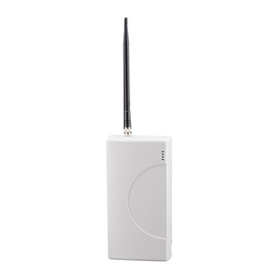
Basic Hardware: Model TG-4 p/n TG4G0001 Model TG-4 (p/n TG4G0001) meets the requirements for Household Burglary, Household Fire, and Combination Burglary/Fire installations. It has a plastic enclosure, and dipole antenna. TG-4 is UL Listed for the following: UL Household Burglary...
Need help?
Do you have a question about the TG-4 and is the answer not in the manual?
Questions and answers