
Related Manuals for IKA C 6000 global standards


Summary of Contents for IKA C 6000 global standards
- Page 1 20000004212 C6000_092016 C 6000 global standards ® C 6000 isoperibol ® Operating instructions...
-
Page 3: Table Of Contents
Connection to the mains power supply Connection of peripherals On/off switch Display and operating elements Explanation of the screen display Working with the IKA C 6000 global standards/isoperibol calorimeter ® Switching on the device System test Switching off the device The standard calorimetric procedure... -
Page 4: Declaration Of Conformity
Fault rectification Checks Accessories and consumables Accessories Technical data Technical data IKA C 6000 global standards ® Technical data IKA C 6000 isoperibol ® Declaration of conformity We declare under our sole responsibility that this product corrosponds to the regulations 2006/42/EC, 2011/65/EU, 2014/30/EU and 2014/35/EU and conforms with the standards or standardized documents EN 61010-1, EN 61010-2-051, EN 61326-1, EN 60529 (A1+A2) and EN ISO 12100. -
Page 5: Safety Instructions
Some materials tend to explode when combusted (e.g. due to formation of peroxides), which could At the end of the work period, close the main cause the decomposition vessel to crack. The IKA ® valve for the oxygen supply. C 6000 global standards/isoperibol calorim-... - Page 6 Note: You can then continue to use the device / C 6010/ 6012 decomposition vessel, see chapter decomposition vessel. „maintenance of the decomposition vessel“. Contact the IKA Service Department to perform ® the pressure test. Comply with the safety instruc- Decomposition vessels are experiment autoclaves tions in this respect.
-
Page 7: Correct Use
• Operation without the cooling unit: Connection decomposition vessel of approx. 5 K). to a water faucet with the pressure valve IKA ® • PC-operation of one or several calorimeters C 25; temperature range 12 °C upto 27 °C; wa- (Software CalWin ®... -
Page 8: Warranty And Liability
Cooling water Mode of operation Mode of operation temperature C 6000 global standards C 6000 isoperibol 12 °C to 20 °C Adiabatic 22 °C Isoperibolic 22 °C Isoperibolic 22 °C Dynamic 22 °C Dynamic 22 °C... -
Page 9: Unpacking
When you unpack the sent immediately (post, rail or forwarder). equipment, check for any damages which may have occurred during transportation. Scope of supply Calorimeter IKA C 6000 global standards/isoperibol ® • Calorimeter IKA C 6000 global standards/isoperibol ®... -
Page 10: Description Of System Components
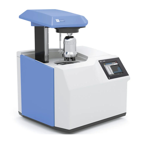
Description of system components ® Calorimeter IKA C 6000 global standards/isoperibol Lift Decomposition vessel Stylus for operating the touch screen Touch Screen Interfaces Water filter Mains power supply Water Oxygen... -
Page 11: Ika
Hoses • Discharge hose C 6000 (empty) • Inflow pipe (in) C 6000 Condenser • Return pipe (out) • Venting hose C 6000 (out) • connection tube C 6000 M 8x1 (in) Commissioning Place of installation A constant ambient temperature is an important For operation of the system the following must be requirement for ensuring the high measuring available at the place of installation:... -
Page 12: Connection To The Condenser
Connection to the water The valve is installed into the line of Operatrion is only allowed with the the water connection, see operating pressure valve IKA C 25! ® instruction IKA C 25. ®... -
Page 13: Connection To The Oxygen Supply
Insert the O connection tube into the calorimeter „IN“ port until it clicks home and connect the free end to the pressure reducer, using the adapters supplied if necessary. IKA ® C 29. Removal entails the same operations performed in the reverse sequence. -
Page 14: Connection Of Peripherals
Connection of peripherals Note: While the peripheral devices are being connected, they and the calorimeter must be turned-off on the mains power switch! RS232 PC: Serial connection for controlling the calorimeter using CALWIN or operating with serial printer C1.50. Standard setting: Baud rate: 9600 Data bits:... -
Page 15: On/Off Switch
On/off switch The device is switched on and off via the on/off switch located on the right-hand side. Switch the device off at the on/off switch. Lift moves upwards. Switch the appliance off only by using the menu com- mands. -
Page 16: Display And Operating Elements
Display and operating elements After the C 6000 global standards/iso- ® peribol calorimeter has been switched on, the touch screen display is active and can be operated using the stylus or finger. Explanation of the screen display Schematic representation of the display components Pos. - Page 17 The contents of the screen display are often dis- tributed over several tabs. You can switch be- tween tabs at any time by clicking on them. Thus for instance the screen display during the calori- metric standard procedure consists of the three List display views „Measurements“, „Device“...
- Page 18 The view „Graph“ shows the temperature by time. The most important actions available at any point in time are gathered together as clickable buttons along the bottom edge of the screen. Switch Switch To initiate an action it is sufficient to click on one of the discrete areas showing the relevant images or text.
- Page 19 Weighted sample Input of a numerical value, such as weight- ed sample: The entire area with the exception of the „Scale“ button is available to be clicked here. A numerical virtual keyboard is opened and can be used to input the value: After the virtual keyboard has been closed with „OK“, the value in the input field is loaded.
-
Page 20: Working With The Ika ® C 6000 Global Standards/Isoperibol Calorimeter
A start screen appears for about 30 seconds, during which the hardware is initialised and the software is loaded. System test The system test is performed automatically every time the IKA C 6000 global standards/isoperibol is ® switched on. -
Page 21: Switching Off The Device
If the cooling water conditions are not correct for First commissioning At first commissioning you must register a de- the selected function of the IKA C 6000 global ® composition vessel: standards/isoperibol, you can select a different To do this, press „Menu on“ button. -
Page 22: The Standard Calorimetric Procedure
The gross calorific value Ho is formed as the Combustion is carried out in a calorimeter under quotient of the amount of heat liberated upon specific conditions. The IKA C 6000 global stan- total combustion of a solid or liquid fuel and the ®... -
Page 23: Corrections
In most cases, no additional combustion For more information on this subject, please con- aid is necessary because the disposable crucible tact IKA ‚ or your nearest authorized dealer. ® itself acts as the combustion aid. -
Page 24: Note On The Sample
Note on the sample The calorimeter system IKA C 6000 global stan- • For substances with low flammability or low ® dards/isoperibol is a precision measuring instru- calorific substances use combustion aids (see ment for the routine determination of calorific „Accessories“). -
Page 25: Complete Combustion
It is also possible to use liquid combustion aids such as paraffin oil. Adjustment (only IKA ® C 6000 global standards) If the device is to be operated in adiabatic func- After successful completion of adjustment the de- tion, prior adjustment in the respective tempera- vice automatically changes the mode of operation ture range (22°C, 25°C or 30°C) is necessary. -
Page 26: Calibrating
Regular calibration is absolutely essential to For more detailed information on calibration obtain accurate measurements! please see the relevant standards. If the IKA ® C 6000 global standards/isoperibol is operated For this purpose, a specific quantity of a reference... -
Page 27: Preparation For Measurement
Preparing measurements The term „measurements“ below refers to both the section „Working with the device“ and „Set- the measurements to calibrate the calorimeter tings“), whilst preparation and performance make system (calibration measurements) and the actual virtually no difference. measurements for determining the calorific value. The difference lies mainly in the evaluation (see The following preparations must be performed If the maximum energy input is exceeded, we... - Page 28 The scroll bar allows you to access additional in- put fields for inputting the external energies. If no special application procedures must be observed you can here specify use of the „IKA ignition ® thread“, „User-defined“ = 0, „User-defined“ = 0 default settings.
-
Page 29: Charging The Decomposition Vessel
You can input values between 0 and 20,000 Joules for „External energy 2“. You can also select specific types of combustion aids from the list. In such cases you must enter the weight of this combustion aid so that the external energy can be calculated. -
Page 30: Starting The Measurement
After the preparation for measurement, a mes- sage appears requiring secure closure of the de- composition vessel, despite there being no de- composition vessel hung in the calorimeter cover. You should acknowledge the message when you have hung the decomposition vessel in the calori- meter cover. - Page 31 The screen switches to the „Device“ tab. You can trace the progress of the measurement both in this tab and also in the „Graphics“ tab. In the area above the record, progress bars for the individual phases of the measurement are shown. Once the measurement has been correctly com- pleted the calculated calorific value and the cal- culated thermal capacity also appear here.
-
Page 32: Evaluation
Evaluation Click on auf the measurement to be evaluated. Then click on the „Evaluation“ button. The fol- lowing screen with several tabs appears. The para- meters for the evaluation are distributed across the „Gross Calorific Value“ and „Net Calorific Value“ tabs. -
Page 33: Menu (Main Overview)
Menu Click the „Menu on“ button to display the menu. Use the scroll bar to display all the menu options. If a measurement has been prepared or selec- ted you will see only a restricted selection of the menu options. „Show/Hide Message Panel“: an information field above the button toolbar is displayed or hid- den. -
Page 34: Library
Library The library screen shows all the measurements within the memory location \FFSDISK\C6000\ tests. In the left hand selection field you can also ex- tend an directory tree which is organised by years and months. Within each month the right hand window then displays the measurement organi- sed by days. -
Page 35: Method Of Operation, Decomposition Vessels And Calibration
C 6000 global standards C 6000 isoperibol ® ® You can select the function of the IKA C 6000 ® global standards/isoperibol from a list. - Page 36 If you wish to change the function for subsequent measurements, click on the „Change“ button to start the system check for the new function. Alternatively you can select a decomposition ves- sel from the updated list of decomposition ves- sels. „Calibration“...
- Page 37 „Control chart“ tab This displays the graphics for the selected calibra- tion with the upper and lower warning and con- trol limits. The scaling is adapted automatically. LWL/UWL and LCL/UCL The LWL and UWL (lower and upper warning li- mits) define the area within which 95% of the calibration measurements should lie.
-
Page 38: Servicing The Decomposition Vessel
You will now see the name and RFID ID of the selected decomposition vessel. Input the Service Code for it and click on the „Renew“ button. You will receive your service code once you have re- gistered on the IKA homepage. ® Switch to the „Decomposition vessel“ tab and click on the „Save“... - Page 39 Select from the list: The selected standard will be applied to all the subsequent measurements. Evaluated measurements will comply with this standard: if a measurement has already been evaluated, the evaluation procedure will be used for any subsequent re-evaluation. Otherwise the current setting for the evaluation procedure will be used.
- Page 40 The default setting is „IKA ignition thread“ You can modify the list or add new ignition aids to it.. Select an ignition aid and click on the „Edit“...
- Page 41 Combustion aid „Combustion aids“ tab There are two different combustion aids available for use in order to achieve correct combustion of samples. The external energies contributed by the aids are input or calculated at preparation of the sample and are included automatically in the calculation of the calorific values.
- Page 42 A serial printer can be connected to PC port of the C 6000. This printer allows printing of the se- quential record of the measurements. No other printing operations can be performed with this printer. We recommend the IKA C 1.50 printer ® with the serial settings 9600-8-N-1.
- Page 43 Sound: Activation of the speakers.
- Page 44 Help and servicing system Help You can activate and display the „Help“ tab at any time to obtain detailed information on the current status and available actions for the calori- meter. Click on either the „Help“ button in the information field or on the „Help“ menu item and switch to the „Help“...
- Page 45 Empty Water: The inner vessel can be emptied manually. Stirrer: Here the operation of the stirrer can be tested. After the start the stirrer speed is displayed. check cooling water: After the start the current cooling water tempera- ture at the entry into the calorimeter is displayed. Cover up/down: The cover can be opened and closed manually.
- Page 46 - > Green = free - > Red = occupied - > Grey = rack not connected/recognised Working with the sample rack and balance If a balance is connected to the IKA C 6000 ® global standards/isoperibol calorimeter, the weighted sample can be sent directly from the...
- Page 47 CAUTION: Before each weighing and transfer of values from the balance, the “TARE” key needs to be pressed. If the crucible is placed in the sample rack, the input field is closed automatically and the prepa- red measurement appears in the measurement window.
- Page 48 It is important to thoroughly which you can obtain from IKA or can download ® clean the inner walls of the vessel, the internal fit- a version for printing from the IKA website at ® tings (brackets, electrodes etc.) and the combus- www.ika.com.
- Page 49 Cleaning • Switch the device off. • Use a suitable brush to clean the sieve inside • Switch the cooling water supply off (switch off and out. • Place the sieve back in the filter. the condenser, clock the water shut-off valve). •...
- Page 50 Help or in the operating instructions, click on the „Restart“ button to start the system test. On suc- cessful completion of the system test the IKA ® 6000 global standards/isoperibol is again availab-...
- Page 51 Fault rectification Display Description What should be done? What happens next? No heating pulse in the inner No increase in temperature Acknowledge the alarm. circuit. within the inner water circuit. Check the cooling water flow Check the circulating pump. Click on „Restart“ to repeat the system test.
- Page 52 Display Description What should be done? What happens next? No increase in temperature after This error message is generated, Acknowledge the error message ignition. if the increase in temperature to revert to the „Wait“ message. has not achieved the specified The sample is combusted.
- Page 53 If the system test was unsuccess- the system test has been com- ful, switch the C 6000 off and on pleted successfully. again. If the system test is unsuccessful again, please contact IKA Cus- ® tomer Service.
- Page 54 „Wait“ the system test has been com- If the system test was unsuccess- pleted successfully. ful, switch the C 6000 off and on again. If the system test is unsuccessful again, please contact IKA Cus- ® tomer Service.
- Page 55 Checks Various major parts of the calorimeter are mo- nitored. Information about when the servicing intervals defined by the manufacturer for these parts fall due is shown in the information field, with the invitation to perform servicing actions. You must then confirm performance of the ser- vicing actions.
- Page 56 C 5 VA VA combustion crucible set (25 pieces) C 710.2 VA VA Combustion crucible large (25 pieces) Quartz dish Quartz dish large C 6000.10 Spare parts kit 1000 C 6000.12 Spare parts kit 1000 For further accessories see www.ika.com.
- Page 57 Technical data C 6000 global standards ® Measuring range max..................J ..........40000 Measuring mode adiabatic 22 °C ..........................yes Measuring mode dynamic 22 °C ..........................yes Measuring mode isoperibolic 22 °C ..........................yes Measuring mode adiabatic 25 °C ..........................yes Measuring mode dynamic 25 °C ..........................yes Measuring mode isoperibolic 25 °C ..........................yes...
- Page 58 Evaluation to ASTM D5865 ............................yes Evaluation to ASTM E711 ............................yes Evaluation to ISO 1928 ............................yes Evaluation to BG T213 .............................yes Width ......................mm ..........500 Depth ......................mm ..........450 Height ......................mm ..........425 Weight ......................kg ............ 29 Permissible ambient temperature min.............. °C ............ 20 Permissible ambient temperature max.
- Page 59 C 6000 isoperibol ® Measuring range max..................J ..........40000 Measuring mode dynamic 22 °C ..........................yes Measuring mode isoperibolic 22 °C ..........................yes Measuring mode dynamic 25 °C ..........................yes Measuring mode isoperibolic 25 °C ..........................yes Measuring mode dynamic 30 °C ..........................yes Measuring mode isoperibolic 30 °C ..........................yes Measuring time* dynamic approx.
- Page 60 Evaluation to ASTM D5865 ............................yes Evaluation to ASTM E711 ............................yes Evaluation to ISO 1928 ............................yes Evaluation to BG T213 .............................yes Width ......................mm ..........500 Depth ......................mm ..........450 Height ......................mm ..........425 Weight ......................kg ............ 29 Permissible ambient temperature min.............. °C ............ 20 Permissible ambient temperature max.
- Page 64 -Werke GmbH & Co.KG ® Janke & Kunkel-Str. 10 D-79219 Staufen Tel. +49 7633 831-0 Fax +49 7633 831-98 sales@ika.de www.ika.com 20005022c...
Need help?
Do you have a question about the C 6000 global standards and is the answer not in the manual?
Questions and answers