Table of Contents
Advertisement
Advertisement
Table of Contents

Related Manuals for IKA C 3000 isoperibol


Summary of Contents for IKA C 3000 isoperibol
- Page 1 20000011772 C 3000_092016 C 3000 isoperibol ® Operating instructions...
-
Page 2: Device Setup
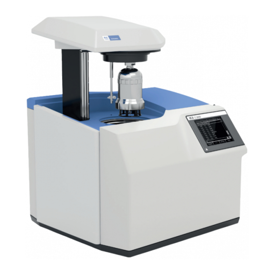
Device setup Lift Decomposition vessel Stylus for operating the touch screen Touch Screen Interfaces Water filter Mains power supply Water Oxygen... -
Page 3: Table Of Contents
Source language: German Contents Page Device setup Declaration of conformity Explication of warning symbols Safety instructions Correct use User instructions System proberties Transport and storage Unpacking Scope of delivery Commissioning Place of installation Connection to the condenser Connection to the water Connection to the oxygen supply Connection to the mains power supply Connection of peripherals... -
Page 4: Declaration Of Conformity
Other Settings Evaluation Measurement Ignition aid Combustion aid Balance Printer Other Help and servicing system Help Maintenance Hardware details Info Cleaning Cleaning the system Servicing and cleaning the filter Troubleshooting Fault rectification Checks Warranty Accessories and consumables Accessories Consumables Technical data Declaration of conformity We declare under our sole responsibility that this product corrosponds to the regulations 2006/42/EC, 2011/65/EU, 2014/30/EU and 2014/35/EU and conforms with the standards or standardized documents EN 61010-1, EN 61010-2-051,... -
Page 5: Safety Instructions
• Tubes and screwed joints for oxygen must be kept free of • The IKA C 3000 isoperibol calorimeter system may be used grease. ® only in conjunction with the decomposition vessels C 6010 Combustion gases are hazardous... -
Page 6: Correct Use
The warning message will then disappear! Note: You can then continue to use the device / decomposi- tion vessel. Correct use The IKA C 3000 isoperibol calorimeter system is used for calorific The IKA C 3000 isoperibol calorimeter system is subject to the ® ®... -
Page 7: Transport And Storage
Unpack the device carefully • Any damage should be notified immediately to the shipping agent (post office, railway network or transport company) Scope of delivery • Calorimeter IKA C 3000 isoperibol • Hoses: ® • C 60.1012 Organizer Discharge •... -
Page 8: Commissioning
“Safety ensuring the high measuring accuracy of the system. The following instructions“. conditions must therefore be fulfilled at the place of installation: Please read these operating instructions carefully. IKA consider ® • No direct solar radiation themselves responsible for the safety, reliability and performance •... -
Page 9: Connection To The Water
Insert the O connection tube into the calorimeter “IN“ port until it clicks home and connect the free end to the pressure reducer, using the adapters supplied if necessary. IKA C 29. Removal ® entails the same operations performed in the reverse sequence. -
Page 10: Connection Of Peripherals
Connection of peripherals While the peripheral devices are NOTICE being connected, they and the calorimeter must be turned-off on the mains power switch! RS 232 PC Serial connection for controlling the calorimeter using CalWin ® operatingwith serial printer C 1.50. Standard setting: Baud rate: 9600... -
Page 11: Display And Operating Elements
Display and operating elements After the IKA C 3000 isoperibol calorimeter has been switched ® on, the touch screen display is active and can be operated using the stylus or finger. Explanation of the screen display Schematic representation of the display components Pos. - Page 12 Status symbols Green tick: Measurement completed but not yet eval- uated, or selection acknowledgement. Pocket calculator: Measurement completed end eval- uated, evaluation inputs can no longer be changed. Blank tick: Measurement prepared but not yet per- formed. Yellow X: Field property not selected, or cancelled before ignition.
-
Page 13: Weighted Sample
Weighted sample Input of a numerical value, such as weighted sample: The entire area with the exception of the “Scale“ button is avail- able to be clicked here. A numerical virtual keyboard is opened and can be used to input the value: After the virtual keyboard has been closed with “OK“, the value in the input field is loaded. -
Page 14: Work With The Device
Work with the device Switching on the device The IKA C 3000 isoperibol is switched on with the On/off switch. ® The cover opens automatically. A start screen appears for about 30 seconds, during which the hardware is initialised and the software is loaded. -
Page 15: Switching Off The Device
Combustion is carried out in a calorimeter under specific condi- tions. The IKA C 3000 isoperibol is filled with a weighed fuel The standard gross calorific value is then determined from the ®... -
Page 16: Corrections
For more information on this subject, please contact IKA ‚ or your ® The sample is weighed directly into the disposable crucible. In nearest authorized dealer. -
Page 17: Complete Combustion
For more detailed information on calibration please see the rele- vant standards. If the IKA C 3000 isoperibol is operated with sev- ® eral different decomposition vessels, you will need to determine the heat capacity of the system for each decomposition vessel. -
Page 18: Preparing Measurements
Preparing measurements The term “measurements“ below refers to both the measurements to calibrate the calorimeter system (calibration measurements) and the actual measurements for determining the calorific value. The difference lies mainly in the evaluation (see the section ˝Wor- king with the device“ and ˝Settings“), whilst preparation and per- formance make virtually no difference. - Page 19 From the list, select a decomposition vessel. The scroll bar allows you to access additional input fields for in- putting the external energies. If no special application procedures must be observed you can here specify use of the ”IKA ignition ®...
-
Page 20: Charging The Decomposition Vessel
Charging the decomposition vessel Please refer to the operating instructions for the C 6010/ C 6012 decomposition vessels. After the preparation for measurement, a message appears re- quiring secure closure of the decomposition vessel, despite the- re being no decomposition vessel hung in the calorimeter cover. When you confirm the prompt, the “Start”... - Page 21 You can then click on the “Start“ button. The screen switches to the “Device“ tab. You can trace the progress of the measurement both in this tab and also in the “Graphics“ tab. In the area above the record, progress bars for the individual phases of the measurement are shown.
-
Page 22: Evaluation
Evaluation Click on auf the measurement to be evaluated. Then click on the “Evaluation“ button. The following screen with several tabs appears. The parameters for the evaluation are distributed across the “Gross Calorific Value“ and “Net Calorific Value“ tabs. Note: The “Net Calorific Value“ tab is not shown at calibration. Now you can input the parameters required for the standard that was selected (here: ASTM D 4809). -
Page 23: Menu (Main Overview)
Menu Click the “Menu on“ button to display the menu. Use the scroll bar to display all the menu options. If a measurement has been prepared or selected you will see only a restricted selection of the menu options. ”Show/Hide Message Panel“: an information field above the button toolbar is displayed or hidden. -
Page 24: Working Mode, Vessels And Calibration
In the left hand selection field you can also extend an directory tree which is organised by years and months. Within each month the right hand window then displays the measurement organised by days. Select the desired day and click on the “Evaluation“ button. The list of the measurements on the selected day is displayed. -
Page 25: "Calibration" Tab
Three additional tabs appear listing the calibration, a check chart of the calibration and the calibration statistics for the selected function and decomposition vessel. You can select the function of the IKA C 3000 isoperibol from ®... -
Page 26: "Control Chart" Tab
You will now see the serial number of the selected decomposition vessel. Input the Service Code for it and click on the “Renew“ but- ton. You will receive your service code once you have registered on the IKA homepage. ®... -
Page 27: Other Settings
Other settings Evaluation ”Evaluation“ tab Default evaluation: After a measurement has been completed, as a rule the results are extended and corrected in accordance with the applicable national or international standards. Select from the list: The selected standard will be applied to all the subsequent mea- surements. -
Page 28: Measurement
If you select “user-defined“ this energy value can also be changed at the preparation of each individual measurement. The default setting is “IKA ignition thread“ ® You can modify the list or add new ignition aids to it.Select an ignition aid and click on the “Edit“... -
Page 29: Combustion Aid
Combustion aid ”Combustion aids“ tab There are two different combustion aids available for use in order to achieve correct combustion of samples. The external energies contributed by the aids are input or calculated at preparation of the sample and are included automatically in the calculation of the calorific values. -
Page 30: Printer
A serial printer can be connected to PC port of the C 3000. This printer allows printing of the sequential record of the measure- ments. No other printing operations can be performed with this printer. We recommend the IKA C 1.50 printer with the serial ®... -
Page 31: Help And Servicing System
Help and servicing system Help You can activate and display the “Help“ tab at any time to obtain detailed information on the current status and available actions for the calorimeter. Click on either the “Help“ button in the informati- on field or on the “Help“ menu item and switch to the “Help“ tab. The “Hardware details“... -
Page 32: Hardware Details
Hardware details In addition you can switch to the “Hardware details“ tab. This tab shows you all the information about the digital inputs and outputs, the temperature values on all the measurement channels, various counters and statuses of accessories. You cannot make any changes here. -
Page 33: Cleaning
For this, use the “certificate of compliance” form which you can obtain from IKA or can download a version for printing from ® In order to obtain accurate measurements it is essential that the the IKA website at www.ika.com. -
Page 34: Troubleshooting
“Confirm“ button is clicked. After you have taken the actions de- scribed in the Help or in the operating instructions, click on the “Restart“ button to start the system test. On successful completion of the system test the IKA C 3000 isoperibol is again available for ® measurements. -
Page 35: Fault Rectification
Fault rectification Display Description What should be done? What happens next? No heating pulse in the inner No increase in temperature within Acknowledge the alarm. circuit. the inner water circuit. Check the cooling water flow Check the circulating pump. Click on “Restart“ to repeat the system test. Click on “Next“... -
Page 36: Checks
Display Description What should be done? What happens next? Converter alarm High-precision temperature measu- Acknowledge the error message in order to switch to the rement is one of the core functiona- “System Check“ status. Press the “Restart“ button. lities of the calorimeter. Any error message regarding the The temperature converter is reset and the system test temperature recording brings the... -
Page 37: Warranty
Combustion bag, 70 x 40 mm (100 pieces) C 12 Combustion bag, 40 x 35 mm (100 pieces) AOD 1.11 Control standard for sulphur and chlorine For further accessories see www.ika.com. Technical data Measuring range max 40000 Measuring mode dynamic 22 °C Measuring mode isoperibolic 22 °C... - Page 38 Cooling medium water quality tap water Type of cooling continuous flow Flow rate min. Flow rate max. Recommended flow rate at 18 °C Oxygen operating pressure max Interface to scales RS 232 Interface to printer USB, RS 232 und network Interface to PC RS 232 Interface to ext.
- Page 40 -Werke GmbH & Co.KG ® Janke & Kunkel-Str. 10 D-79219 Staufen Tel. +49 7633 831-0 Fax +49 7633 831-98 sales@ika.de www.ika.com 20012285a...
Need help?
Do you have a question about the C 3000 isoperibol and is the answer not in the manual?
Questions and answers