Table of Contents
Advertisement
Quick Links
TB 08-03
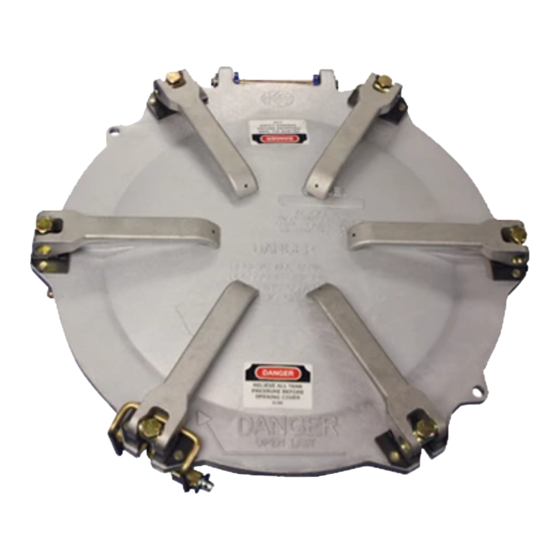
STEP 1: See Figure 1. After cover (1) is installed on weld ring (2) with hinge pin (3), position
cam levers (4) on cover and close cam at each hold-down position. Minimal friction
resistance between bottom of cam and top of wear plate (5) should be evident. See
STEP 2: Insure upper pivot pin is centered between cam lever "ears". Use socket wrench to
tighten cam adjustment bolt (6) on top until gasket and weld rings top surface make
contact at each of the six cam locations
STEP 3: To insure a good peripheral sea tighten each cam adjustment bolt (6) shown in
FIGURE 1 to 13 lbs-ft (up to 16 lbs-ft). Cam tightening order should be done in a star
pattern which is shown in FIGURE 2. Tighten starting with cam number 1 and move
sequentially to cam number 6.
NOTE (1):
NOTE (2):
CAM LEVER ADJUSTMENT PROCEDURE
LM 20" MANHOLE ASSEMBLY
WITH ADJUSTABLE CAMS
Gaskets should be checked periodically for cuts or accumulation of
product and could result in sealing problems. Replace all damaged
gaskets.
Cam levers and wear plates need to be inspected for excessive wear in
the area where they make contact. If the cam lever opens easily with
minimal resistance, replace the worn components.
RevA Apr.2021
Advertisement
Table of Contents

Related Manuals for Dover Civacon LM1051


Summary of Contents for Dover Civacon LM1051
- Page 1 TB 08-03 CAM LEVER ADJUSTMENT PROCEDURE LM 20” MANHOLE ASSEMBLY WITH ADJUSTABLE CAMS STEP 1: See Figure 1. After cover (1) is installed on weld ring (2) with hinge pin (3), position cam levers (4) on cover and close cam at each hold-down position. Minimal friction resistance between bottom of cam and top of wear plate (5) should be evident.
- Page 2 NOTE: All information subject to engineering and/or other changes. All trade names are copyrighted. Patents Pending. ©2018 Civacon. ©2018 Delaware Capital Formation, Inc. All Rights Reserved. DOVER and the DOVER logo are registered trademarks of Delaware Capital Formation, Inc., a wholly-owned subsidiary of Dover Corporation.
Need help?
Do you have a question about the Civacon LM1051 and is the answer not in the manual?
Questions and answers