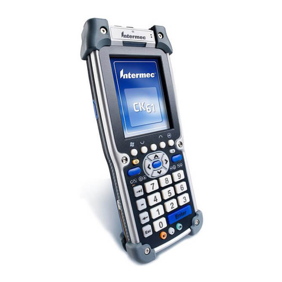
Intermec CK61 Installation Instructions Manual
Vehicle dock kit
Hide thumbs
Also See for CK61:
- User manual (190 pages) ,
- Supplementary manual (4 pages) ,
- Quick start manual (2 pages)
Table of Contents
Advertisement
Quick Links
Advertisement
Table of Contents

Subscribe to Our Youtube Channel
Summary of Contents for Intermec CK61
- Page 1 Installation Instructions Vehicle Dock Kit...
- Page 2 The information contained herein is provided solely for the purpose of allowing customers to operate and service Intermec-manufactured equipment and is not to be released, reproduced, or used for any other purpose without written permission of Intermec Technolgies Corporation.
- Page 3 Document Change Record This page records changes to this document. This document was originally released as Revision A. Revision Letter Date Description of Change 03/2007 Added pin-out information for the 3-pin notched DC power connector. Rewrote instructions to address multiple mobile computers.
- Page 4 Vehicle Dock Kit Installation Instructions...
-
Page 5: Table Of Contents
Installation Guidelines ......7 Vehicle Electrical Considerations..... .7 Installing the Vehicle Battery Power Cable . - Page 6 Vehicle Dock Kit Installation Instructions...
-
Page 7: Installation Guidelines
Installation Guidelines These instructions detail tasks for various installation options. Your tasks include: • Route and install the gray battery power cable to the vehicle battery terminals • Install an in-line fuse holder • Install the mounting hardware and vehicle dock •... -
Page 8: Installing The Vehicle Battery Power Cable
Installing the Vehicle Battery Power Cable Use cable clamps or wire-ties at least every 46 cm (18 in) when installing cables on a vehicle. This eliminates loose or sagging cables, guards against breakage and ensures that they do not pose a hazard to the vehicle operator or to other workers. -
Page 9: Connecting To The Side Battery Terminal
Brown wire Vehicle battery (gray) cable Red wire Fuse link splice Connecting to the Side Battery Terminal It is very important to make sure that you make the correct cable to battery connections, because electrical energy from vehicle batteries can harm equipment and people. -
Page 10: Connecting To The Top Battery Terminal
Repeat Steps 2 through 8 for the negative (brown) wire from the battery cable, hooking up the negative cables to the negative (-) battery terminal. Batttery terminal post (positive) Washers Red wire (positive) Power cable Connecting to the Top Battery Terminal Because electrical energy from vehicle batteries can harm equipment and people, it is very important to make sure that you make the correct cable to... -
Page 11: Fastening The Ground Strap
Repeat Steps 3 through 6 for the negative (brown) wire from the battery cable, connecting the wire to the negative (-) battery terminal. Washers Nut (2) Red wire (positive) Gray power cable Fastening the Ground Strap The white connector on the battery power cable has a braided green wire grounding strap that you must fasten to the vehicle’s sheet metal to ensure proper cable shielding. -
Page 12: Verifying The Dock Power Cable Polarity
Verifying the Dock Power Cable Polarity Use this illustration to verify that you have installed your vehicle dock power cables correctly. Below are the pin descriptions for the notched DC power connector on the dock power cable. Use a volt meter to verify whether +12 volts is on pin 2 before you make the final cable connection. -
Page 13: Installing An Optional Printer
Mounting kit attachment plate USB/serial adapter connector CN3 Vehicle Dock Note: See your Intermec representative for information about docks that support other mobile computers not mentioned on this page, such as the CK61 or CN2. Installing an Optional Printer If you are adding a printer to your system, you need the power cables to connect the printer and vehicle dock to the vehicle battery. -
Page 14: Installing The Vehicle Dock And Printer
For installation in a system that includes a printer refer the following wiring diagram. “Y” power cable Battery cable Battery Cables for Vehicle Dock, Printer, and Vehicle Battery Description “Y” power cable Battery cable (gray) Installing the Vehicle Dock and Printer 1 Install a printer-specific “Y”... -
Page 15: Jump-Starting Your Vehicle
To modify the black dock cable to connect into a vehicle fuse block • Switch to using the fuse block cable P/N 226-109-003, or Cut off the white connector from the end of the dock power cable and wire it directly to the fuse block. Note the difference in polarity between these two cables. - Page 16 Worldwide Headquarters 6001 36th Avenue West Everett, Washington 98203 U.S.A. tel 425.348.2600 fax 425.355.9551 www.intermec.com Vehicle Dock Kit Installation Instructions *962-000-021C* P/N 962-000-021C...


Need help?
Do you have a question about the CK61 and is the answer not in the manual?
Questions and answers